


LTE 5100

Notice
The information in this guide is subject to change without notice.
Compaq Computer Corporation shall not be liable for technical or editorial
errors or omissions contained herein; nor for incidental or consequential
damages resulting from the furnishing, performance, or use of this
material.
This guide contains information protected by copyright. No part of this
guide may be photocopied or reproduced in any form without prior written
consent from Compaq Computer Corporation.
Copyright 1995, 1996 Compaq Computer Corporation.
All rights reserved. Printed in the U.S.A.
Compaq, Deskpro, LTE, Contura, Presario, ProLinea
Registered U. S. Patent and Trademark Office.
LTE 5000 is a trademark of Compaq Computer Corporation.
Contura Registered in the Philippines Patent Office.
Microsoft, MS-DOS, and Windows are registered trademarks of Microsoft
Corporation.
The software described in this guide is furnished under a license
agreement or nondisclosure agreement. The software may be used or copied
only in accordance with the terms of the agreement.
Product names mentioned herein may be trademarks and/or registered
trademarks of their respective companies.
MAINTENANCE AND SERVICE GUIDE
COMPAQ LTE 5000 FAMILY OF PERSONAL COMPUTERS
First Edition (September 1995)
Second Edition (November 1996)
Documentation Part Number 213583-002
Spare Part Number 213622-002
Chapter 1. Product Description
1.1 Computer Features and Models
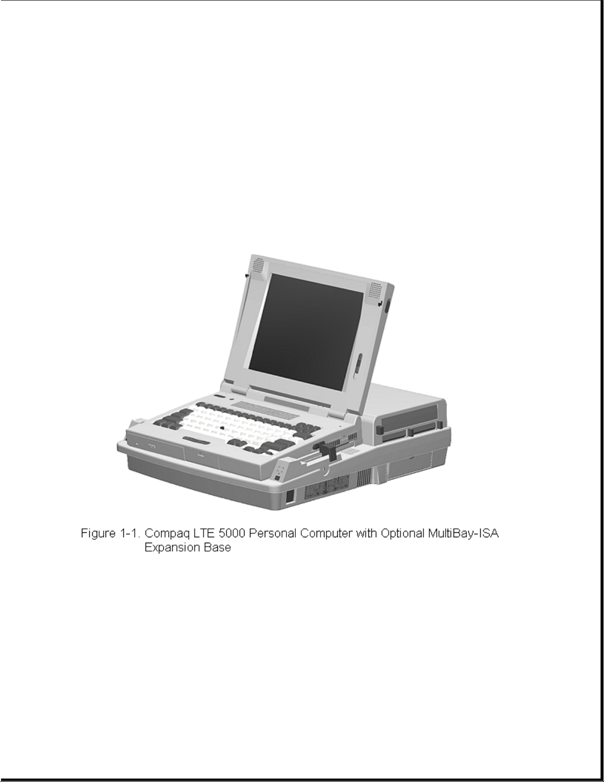
The Compaq LTE 5000 Family of Personal Computers introduces a new
generation of performance notebook computers with advanced modularity,
Pentium processors with 64-bit architecture, PCI local bus graphics, and
extensive multimedia support. This full- function family of notebook
computers allows desktop functionality and connectivity via an optional
expansion base.
1.1.1 Computer Features
The Compaq LTE 5000 Family of Personal Computers has the following
standard features:
o Extensive multimedia support with integrated 16-bit digital stereo audio
(Microsoft Windows Sound System and SoundBlaster Pro compatible), dual
speakers, microphone, full motion video support, optional CD-ROM drive,
and optional MPEG and TV Video Adapter
o 75, 90, 100, 120, 133, or 150-MHz Intel Pentium processor with 64-bit
architecture

o 8 or 16 MB of RAM, expandable to 72 or 80 MB
o 512 KB of 64-bit write-back, synchronous, level-2 cache memory available
on the LTE5400 model; 256 KB of 64-bit write-back, synchronous,
level-2 cache memory available on all other models
o Upgradable flash ROM BIOS
o High-performance 32-bit PCI local bus graphics with hardware-assisted
Motion Video Acceleration (MVA)
o Color TFT VGA or SVGA, CSTN VGA or SVGA, or CTFT 1024 x 768 display
panels
o Keyboard with built-in EasyPoint II pointing device and mouse buttons
o Removable hard drive
o MultiBay modular device bay that supports a CD-ROM drive, a second hard
drive, a second battery pack, or diskette drive, and a full-length ISA
slot that allows addition of an ISA expansion board (ISA slot available
with MultiBay ISA Expansion Base only)
o Two Type III PC Card (PCMCIA) slot that supports one Type III, two Type
I, or two Type II PC Cards, LAN connection or data/fax modem
o Infrared port for IrDA wireless data transfer, printing, and drive
synchronization
o Ports and connectors for external equipment (see Section 1.3)
o Preinstalled software
o Security features
o Desktop functionality available with the optional Compaq LTE 5000
MultiBay Expansion Base or MultiBay ISA Expansion Base.
1.1.2 Computer Models
The Compaq LTE 5000 Family of Personal Computers is available in the
models shown in Table 1-1.
Table 1-1. Compaq LTE 5000 Family of Personal Computers Models
===========================================================================
Model Processor Display Hard Drive CD-ROM Drive
===========================================================================
LTE 5000 Model Pentium/75 10.4-inch 510 MB Optional
510 CSTN CSTN/VGA
--------------------------------------------------------------------------LTE 5000 Model Pentium/75 11.3-Inch 810 MB Optional
810 CSTN CSTN/SVGA
--------------------------------------------------------------------------LTE 5000 Model Pentium/75 10.4-Inch 810 MB Optional
810 CTFT CTFT/VGA
--------------------------------------------------------------------------LTE 5100 Model Pentium/90 10.4-Inch 810 MB Optional
810 CTFT CTFT/SVGA
--------------------------------------------------------------------------LTE 5100 Model Pentium/90 10.4-Inch 810 MB Yes

810 CD CTFT CTFT/SVGA
--------------------------------------------------------------------------LTE 5150 Model Pentium/100 11.3-inch 810 MB Yes
810 CSTN 800 CTFT/SVGA
x 600
--------------------------------------------------------------------------LTE 5200 Model Pentium/120 10.4-inch 1.35 GB Optional
1350 CTFT CTFT/SVGA
--------------------------------------------------------------------------LTE 5250 Model Pentium/120 10.4-inch 810 MB Yes
810 CTFT CTFT/SVGA
800 x 600
--------------------------------------------------------------------------LTE 5280 Model Pentium/120 11.3-inch 810 MB Yes
810 CTFT CTFT/SVGA
800 x 600
--------------------------------------------------------------------------LTE 5280 Model Pentium/120 11.3-inch 1.35 GB Yes
1350 CTFT CTFT/SVGA
800 x 600
--------------------------------------------------------------------------LTE 5300 Model Pentium/133 12.1-inch 1.35 GB Yes
1350 CTFT CTFT/SVGA
800 x 600
--------------------------------------------------------------------------LTE 5300 Model Pentium/133 12.1-inch 2.16 GB Yes
2160 CTFT CTFT/SVGA
800 x 600
--------------------------------------------------------------------------LTE 5380 Model Pentium/133 12.1-inch 2.16 GB Yes
2160 CTFT CTFT/10 X 7
1024 x 768
--------------------------------------------------------------------------LTE 5400 Model Pentium/150 12.1-inch 2.16 GB Yes
2160 CTFT CTFT SVGA
800 x 600
===========================================================================
1.1.3 Preinstalled Software
The computer can have either Windows 3.1 or Windows 95 installed.
Windows 3.1 Software Components
The following software is preloaded if Windows 3.1 is installed:
o MS-DOS 6
o Microsoft Windows 3.1
o Cirrus GD-754x Video Driver
o TEAC CD-40E CD-ROM Driver and CD Audio Player for DOS
o ESS Audio Driver and Audio Clip Library
o Compaq Sound System Version 1.70
o Compaq Network Interface Drivers

o Compaq PCMCIA 3.14
o Logitech Mouse Ware 6.46
o PUMA TranXit Version 1.03
o Microsoft Video for Windows 1.10e (Runtime version)
o Machine Check Version 1.1 (MACHCHK.SYS)
o SystemSoft Suspend-To-Disk Utility 2.20.00 (0VMAKFIL.EXE)
o Compaq Supplementary Programs
o Microsoft Supplementary Programs
o SAFETY & COMFORT GUIDE
o COMPAQ DICTIONARY
o COMPAQ USER'S GUIDE
o ONLINE OPTIONS CATALOG
o Compaq Diagnostics for Windows 1.05
o CompuServe WinCIM (1.4/1.2/1.31D/1.31F)
o America Online for Windows (North America only)
Windows 95 Software Components
The following software is preloaded if Windows 95 is installed:
o Cirrus Logic GD-754x Video Driver
o TEAC CD-40E CD-ROM Driver
o Compaq PCMCIA 3.14 Installer for Windows 95
o Logitech Mouse Ware 6.50
o Machine Check Version 1.1 (MACHCHK.SYS)
o SystemSoft Suspend-To-Disk Utility 2.20.00 (0VMAKFIL.EXE)
o Microsoft Infrared Monitor and Direct Cable Connect
o SAFETY & COMFORT GUIDE
o COMPAQ DICTIONARY
o COMPAQ ONLINE USER'S GUIDE
o ONLINE OPTIONS CATALOG
1.1.4 Intelligent Manageability
Intelligent Manageability combines innovative hardware technology with PC

LAN management tools from Compaq and other leading vendors to make Compaq
portable computers easier to inventory, troubleshoot, and protect.
Asset Management
AssetControl is asset management software designed to cut the time and
cost of conducting a physical inventory of personal computers, key
components, and monitors. AssetControl is preinstalled on portable
computers, key components, and monitors that support the Video Electronics
Standards Association Data Display Channel (VESA DDC) and Extended Display
Identification Data (EDID) standards.
AssetControl features make it easy and inexpensive to maintain an
accurate, up-to-date inventory. Detailed inventory information, including
manufacturer, model, serial number, asset tag, and ROM revision level can
be viewed, printed, or saved electronically using Compaq Insight Personal
Edition or Compaq Insight Manager.
Compaq Insight Personal Edition refers to Intelligent Manageability
software that diagnoses portable computer hardware, monitors the internal
system temperature and IntelliSafe hard drive, and then displays a
prefailure warning message on detecting a system temperature or hard drive
fault.
Compaq Insight Manager refers to Information Manageability software that
helps manage servers and personal computers on a network. Compaq Insight
Manager features intelligent monitoring and alerting, remote maintenance,
and visual control of network resources.
Fault Management
Fault Management is a utility designed to help prevent the loss of
critical data. This feature is available only in the 2.16GB DFP (SMART
system compliant drives). Fault Management has the following features:
o SMART (IntelliSafe) hard drive - Constantly monitors hard drive activity
to predict failures before they occur.
o Temperature sensing - Hardware and software that tracks the internal
temperature of the computer and displays a warning message when the
normal range is exceeded.
Compaq Insight Personal Edition displays a pop-up message to notify you
when a hard drive or system temperature fault is detected. If the computer
is connected to a network managed by Compaq Insight Manager, fault notices
are also sent to the network management application.
Security Management
The security management utility provides a set of security features to
protect the computer and data from unauthorized access.
o Passwords - Prevents unauthorized access to information stored on the
computer or network.
o Drive security - Prevents starting the computer from the diskette drive
and reading information from the diskette drive.
o Device disabling - Prevents unauthorized data transfer over fax/modems,
serial ports, parallel ports, and infrared ports.

1.1.5 Security Features
The computer has the following security features:
o Ability to secure drives in the dedicated hard drive bay and computer
MultiBay
o Ability to secure the computer and either MultiBay Expansion Base to an
immovable object with an optional cable lock
o Ability to establish power-on and setup passwords and to disable ports
and devices from the Security menu in Computer Setup
1.1.6 Power Management
Power Management offers three levels of power conservation:
o High: Provides the maximum amount of power conservation and the maximum
battery operating time from a single charge.
o Medium: Provides a balance between performance and battery life (factory
default).
o Custom: Conserves power according to user-specified timeout settings.
The conservation level sets the timeouts for Standby (Suspend),
Hibernation, drives, and screens. Use the Fn+F7 hotkeys to toggle off and
on the power management settings in Computer Setup and Windows Power
Properties.
Selecting to disable the infrared port under the Security menu also
conserves power.
Chapter 1.2 Computer Options
The options that are available from Compaq for the computer are described
in the following sections.
1.2.1 MultiBay Expansion Base and MultiBay ISA Expansion Base
The MultiBay Expansion Base and the MultiBay ISA Expansion Base provide
two additional MultiBay device bays, two PC Card Type III slots,
integrated Ethernet, integrated stereo speakers, and computer I/O port
replication. The expansion bases are described in Section 1.5. When the
computer is docked in an expansion base, the total system functionality
includes:
o Support for up to three MultiBay devices simultaneously
o Overall system support for up to four hard drives or two diskette drives
o Up to three CD-ROM drives installed as follows:
- Three CD-ROM drives: The two in the expansion base must be used for
data; the CD-ROM drive in the computer can then be used for audio or data.

- Two CD-ROM drives: You can have one in the expansion base and one in
the computer; either drive can be data or audio. If both drives are in
the expansion base, they must be for data only.
- One CD-ROM drive: It can be either data or audio and in either the
computer or expansion base.
o Two Type III PC Card slots
o Overall system support for up to four PC cards
o Charging of up to four battery packs
The MultiBay ISA Expansion Base provides the same functionality as the
MultiBay Expansion Base, with the following additional features:
o One ISA Expansion slot allows ability to add a full-length ISA expansion
board
o Additional ventilation exhausts on both sides of the expansion base for
increased ventilation
o High performance stereo speakers and new audio bass ports on both sides
of the expansion base for "PremierSound" CD-quality audio
1.2.2 System Memory Options
The main memory subsystem supports a minimum standard 8 MB or 16 MB of
DRAM, expandable to a maximum of 72 or 80 MB. The minimum standard DRAM is
integrated on the processor board. The upgrade DRAM is accomplished with
memory expansion boards that are available in 8, 16, 32, and 64 MB
increments. The memory expansion boards require no special tools for
installation and can be installed by the inexperienced user. System memory
can be upgraded according to the schedule in Table 1-2:
Table 1-2. Memory Upgrade Schedule
===========================================================================
Base Memory Memory Expansion Board Total Memory
===========================================================================
8/16 MB None 8/16 MB
8/16 MB 8 MB 16/24 MB
8/16 MB 16 MB 24/32 MB
8/16 MB 32 MB 40/48 MB
8/16 MB 64 MB 72/80 MB
===========================================================================
1.2.3 Mass Storage Options
The following mass storage options are available for the computer:

o 3.5-inch 1.44 MB Diskette Drive
o 510 MB IDE Hard Drive
o 810 MB IDE Hard Drive
o 1.35 GB IDE Hard Drive
o 2.16 GB w/DFP IDE Hard Drive
o 2.16 GB IDE Hard Drive
Diskette Drive
The computer uses a 3.5-inch diskette drive that is enclosed in a module
that fits into the MultiBays of the computer or the MultiBay Expansion
Base and the MultiBay ISA Expansion Base. The diskette drive is a
three-mode type that is compatible with 1.44 MB, 1.2 MB and 720K AT drive
types. The system supports a maximum of two diskette drives: one in the
computer, one in the MultiBay Expansion Base. When using Windows 95, real
mode drivers must be used for a diskette drive in the expansion base. For
more information see "Solving Diskette and Diskette Drive Problems" in
Chapter 2.
Hard Drive
The computer supports an IDE hard drive in the dedicated hard drive bay.
Cable select technology is employed for device 0/device 1 (master/slave)
selection. The hard drive can be locked in place with the hard drive
security screw installed adjacent to the hard drive release on the bottom
of the computer. See Appendix C for information on using Compaq LTE Elite
hard dives in the computer.
1.2.4 CD-ROM Drive
The modular, 2x, 4x, and 6x CD-ROM drives are available from Compaq as a
standard model or an option for the computer or either expansion base. The
CD-ROM drive is compatible with industry-standard CD-ROM disc media and
formats. It can read:
o CD-Digital Audio
o CD-ROM Mode 1 and Mode 2
o CD-ROM/XA Mode 2 (Form 1 and Form 2)
o CD-I Mode 2 (Form 1 and Form 2)
o Video CD
o Photo CD (single and multisession)
o ISO 9660 and High Sierra

1.2.5 MPEG and TV Video Adapter
The MPEG and TV Video Adapter option is supported with the computer and
both expansion bases. This option provides an MPEG decoder for high
quality digital video playback with Windows scaling and interleaved stereo
audio, S-Video I/O for laser disc quality playback video, and composite
video supporting the NTSC/PAL formats.
1.2.6 Miscellaneous Options
The following options for the computer are also available from Compaq:
o AC Adapter
o Automobile Adapter
o NiMH Battery Pack
o Battery Fastcharger
o Enhanced III External Keyboard
o Compaq Mouse
o Carrying Case
o MultiBay Device Carrying Case
o MultiBay Hard Drive Adapter
AC Adapter
The AC Adapter supplies DC voltage to the system DC-to-DC converter for
use by the system to operate and/or charge the installed battery pack(s).
The adapter provides sufficient power to charge each main battery pack in
1.5 hours or less with the system off. The adapter also powers the Battery
Fastcharger.
Automobile Adapter
The Automobile Adapter is used to charge the computer from an automobile
battery. It also powers the Battery Fastcharger.
External Battery Fastcharger
The external Battery Fastcharger is available from Compaq and has the
following features:
o Two battery charge bays
o Fast charging of one battery in 1.5 hours
o Fast charging of two batteries in 3 hours
It requires the AC Adapter or Automobile Adapter for power.
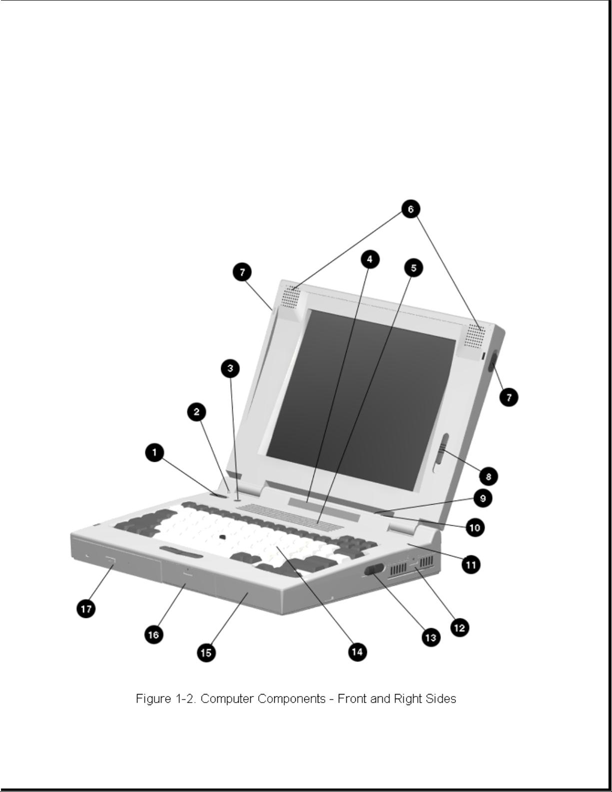
Chapter 1.3 Computer External Components
The external components on the front and right sides of the computer are
shown in Figure 1-2 and are described in Table 1-3.
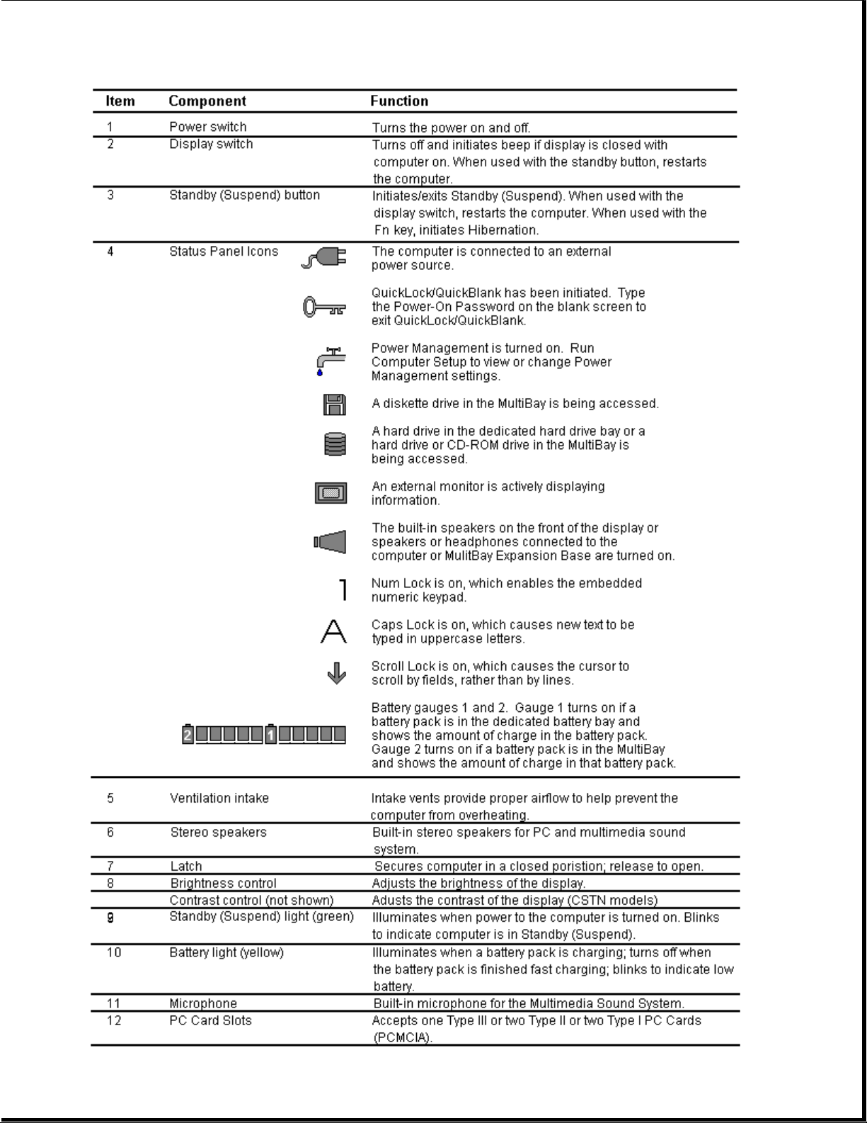
Table 1-3. Computer Components - Front and Right Sides

===========================================================================
Item Component Function
===========================================================================
1 Power switch Turns the power on and off.
--------------------------------------------------------------------------2 Display switch Turns display off and initiates beep if
display is closed with computer on. When
used with the standby button, restarts the
computer.
--------------------------------------------------------------------------3 Standby switch Initiates/exits Standby. When used with
the display switch, restarts the
computer. When used with the Fn key,
initiates Hibernation.
--------------------------------------------------------------------------4 Status panel icons The computer is connected to an external
power source.
QuickLock/QuickBlank has been initiated.
Type the power-on password on the
blank screen to exit
QuickLock/QuickBlank.
Power Management is turned on. Run
Computer Setup to view or change
Power Management settings.
A diskette drive in the MultiBay is
being accessed.
A hard drive in the dedicated hard
drive bay or a hard drive or CD-ROM
drive in the MultiBay is being accessed.
An external monitor is actively
displaying information.
The built-in speakers on the front of the
display or speakers or headphone
connected to the computer or expansion
base are turned on.
Num lock is on, which enables the
embedded numeric keypad.
Caps Lock is on, which causes new text
to be typed in uppercase letters.
Scroll Lock is on, which causes the
cursor to scroll by fields, rather than
by lines.
Battery gauges 1 and 2. Gauge 1 turns on
if a battery pack is in the dedicated
battery bay and shows the amount of
charge in the battery pack. Gauge 2 turns
on if a battery pack is in the MultiBay
and shows the amount of charge in that
battery pack.

--------------------------------------------------------------------------5 Ventilation intake Intake vents provide proper airflow to
help prevent the computer from
overheating.
--------------------------------------------------------------------------6 Stereo speakers Built-in stereo speakers for PC and
multimedia sound system.
--------------------------------------------------------------------------7 Latch Secures computer in a closed position;
release to open.
--------------------------------------------------------------------------8 Brightness control Adjusts the brightness of the display.
Contrast control (not Adjusts the contrast of the display
shown) (CSTN models).
--------------------------------------------------------------------------9 Standby (suspend) light Illuminates when power to the computer
(green) is turned on. Blinks to indicate
computer is in Standby (Suspend).
---------------------------------------------------------------------------
10 Battery light (yellow) Illuminates when a battery pack is
charging; turns off when the battery
pack is fully charged; blinks to
indicate low battery.
---------------------------------------------------------------------------
11 Microphone Built-in microphone for the Compaq
Sound System.
---------------------------------------------------------------------------
12 PC Card slots Accepts one Type III or two Type II or
two Type I PC Cards (PCMCIA).
---------------------------------------------------------------------------
13 Battery release Releases a battery pack in the battery
compartment.
---------------------------------------------------------------------------
14 Keyboard Keyboard with EasyPoint II pointing
device and pick buttons.
---------------------------------------------------------------------------
15 Battery compartment Dedicated battery compartment for the
main battery pack.
---------------------------------------------------------------------------
16 Hard drive bay Dedicated hard drive bay.
---------------------------------------------------------------------------
17 MultiBay Bay that supports multiple devices:
CD-ROM drive, hard drive, battery pack,
or diskette drive.
===========================================================================
The external components on the rear and left sides of the computer are
shown in Figure 1-3 and described in Table 1-4.
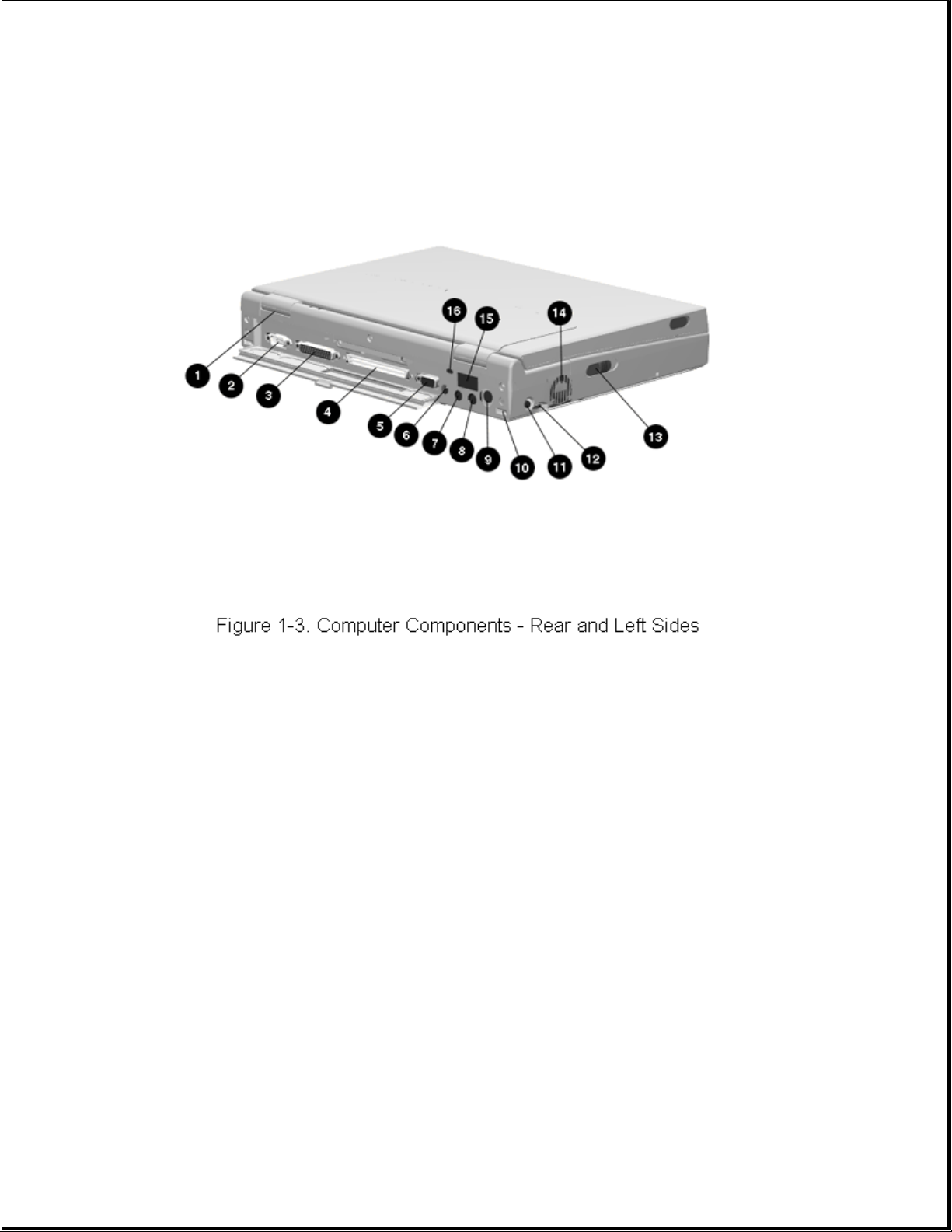
Table 1-4. Computer Components - Rear and Left Sides
===========================================================================
Item Component Function
===========================================================================
1 Serial number Identifies the computer.
--------------------------------------------------------------------------2 Serial connector Connects optional serial devices.
--------------------------------------------------------------------------3 Parallel connector Connects optional parallel devices.
--------------------------------------------------------------------------4 External options Connects the expansion base or the
connector optional Automobile Adapter.
--------------------------------------------------------------------------5 External monitor connector Connects an external monitor.
--------------------------------------------------------------------------6 Power connector Connects the AC Adapter or the
optional Automobile Adapter.
--------------------------------------------------------------------------7 Stereo speaker/headphone Connects external speakers or
jack headphones.
--------------------------------------------------------------------------8 Stereo line in jack Stereo line-in jack for CD player,
tape deck, tuner, or other line level
audio source.
--------------------------------------------------------------------------9 Keyboard/mouse connector Connects an external keyboard, numeric
keypad, PS/2 mouse, or other pointing device.

---------------------------------------------------------------------------
10 Docking sensor Access to a microswitch that initiates
the docking scenario when the computer
is being docked. Also serves as a
guide for the MPEG Adapter.
---------------------------------------------------------------------------
11 Mono microphone jack Connects a powered electric condenser
microphone.
---------------------------------------------------------------------------
12 Volume control Controls volume to the built-in
speakers or to external speakers or
headphones connected to the computer
or MultiBay Expansion Base.
---------------------------------------------------------------------------
13 MultiBay device release Releases a drive or battery pack from
the MultiBay.
---------------------------------------------------------------------------
14 Ventilation exhaust Exhaust vent for proper airflow to
help prevent the computer from
overheating.
---------------------------------------------------------------------------
15 Infrared port Transfers data to another computer or
external device that accepts IrDA
format.
---------------------------------------------------------------------------
16 Security slot Provision for an optional security
cable lock to be attached to the
computer.
===========================================================================
Chapter 1.4 Design Overview - Computer
This section presents a design overview of the computer. The discussion is
limited to the field replaceable parts. All replaceable parts are
identified in Chapter 3, and removal/replacement procedures are presented
in Chapter 5.
The computer is a traditional clamshell design with a display unit and
system unit. The computer opens to reveal a backlighted LCD display and
keyboard. The display is designed for a continuously adjustable tilt
angle. The system unit houses the system board, processor board, power
board, keyboard, I/O ports, operator controls and indicators, mass storage
device bays, and battery bay.
The main components of the system unit include the following:
o Processor (Intel Mobile Pentium 75 MHz, 90MHz, 100MHz, 120MHz, 133mhz,
or 150 MHz)
o System controller (OPTi 556/557/558N, OPTi 602A)
o VGA controller (Cirrus CL-GD754x)
o Keyboard controller (Intel 80C51SL)
o PCMCIA controller (Cirrus 6722)

o Super I/O (National 87334)
o Audio controller (ESS688 or ESS1688)
o Power controller (47P440AF)
The boards on which these controllers reside are identified in the
sections that follow.
1.4.1 Display Unit
The display unit includes the following field replaceable components:
o Display assembly
o Display bezel with speakers
o Release latches
o Brightness control actuator
o Contrast control actuator (CSTN models only)
o Clutch assemblies
o Compaq logo
Display Assembly
The display assembly is replaced as a complete unit that includes:
o LCD panel
o LCD inverter
o Display bezel
o Stereo speakers
o Clutch assemblies
o Release latches
o Brightness control actuator
o Contrast control actuator (CSTN models only)
NOTE: The display bezel, release latches, brightness/contrast control
actuator(s), Compaq logo, and clutch assemblies can also be replaced
individually. The speakers are permanently installed on the display
bezel.

The following LCD panels are supported:
o 10.4-inch (26.4 cm) CSTN VGA Display (640 x 480)
o 11.3-inch (28.7 cm) CSTN SVGA Display (800 x 600)
o 10.4-inch (26.4 cm) CTFT VGA Display (640 x 480)
o 10.4-inch (26.4 cm) CTFT VGA Display (800 x 600)
o 11.3-inch (28.7 cm) CTFT SVGA Display (800 x 600)
o 12.1-inch (30.7 cm) CTFT SVGA (800 x 600)
o 12.1-inch (30.7 cm) CTFT 1024 x 768 Display
Both LCD panels have a controllable backlight intensity that can be
adjusted with a slide switch. The CSTN (dual scan) panels also have a
slide switch for contrast control.
The LCD panel inverter cable plugs into an 8-pin connector on the
processor board. The LCD cable plugs into a connector on the system board.
The inverters and cables differ according to the display type and
manufacturer and cannot be interchanged. All of the display cables are
routed to the system unit in the vicinity of the clutches.
NOTE: It is important that these instructions be followed when replacement
of any part requires removal of the display assembly.
Slide the display assembly back in place and replace all screws. The
screws must be fully tightened to ensure that they do not touch the
expansion base sensor located near the left hinge. Failure to properly
seat the screws may prevent the unit from booting up.
NOTE: Use Fn+F4 hotkeys to switch between external, internal, and
simultaneous display. (The CSTN 800 x 600 does not support
simultaneous display.)
Display Bezel With Speakers
The display bezel attaches to the display unit with a snap action and is
secured with a screw at each corner. Screw covers are installed over the
screw heads. After removing these screws, use a Compaq bezel removal tool
to separate the bezel from the display assembly. The display bezel can be
removed without separating the display unit from the system unit.
The internal stereo speakers are 0.5-watt, 8-ohm, permanently installed in
the top corners of the display bezel and are installed as a unit with
cabling attached. The speaker cable is routed into the system unit and
connects to a 4-pin connector adjacent to the 30-pin LCD connector on the
system board. The CPU cover is easily removed from the system unit to
access this connector.
NOTE: Use Fn+F5 hotkeys to toggle speakers/headphones off and on.

Release Latches
The release latches serve to lock the display and system units together
when the computer is in the closed position. Each latch assembly consists
of three parts:
o Latch actuator
o Latch hook
o Latch spring
The release latch assembly is available as a field replaceable unit. The
display bezel must be removed to replace the latch assemblies.
The release latches are mounted in the display unit back cover. The
display bezel must be removed to access the latches. The latches snap into
place and require a simple depression of a tab to be released from the
display cover.
Brightness/Contrast Control Actuator(s)
The displays have a controllable backlight intensity that can be adjusted
with a slide switch. The CSTN panels also have slide switch for contrast
control. The actuators for these adjustments are available as field
replaceable units.
The brightness/contrast control actuator(s) (contrast control actuator on
CSTN displays only) are mounted on the display bezel with a snap action.
The display bezel must be removed to allow the tabs on the back side of
the actuator to be depressed for removal. When installing a display bezel,
make certain the brightness/contrast actuator(s) aligns with the
brightness/contrast control(s) in the display assembly.
Clutch Assemblies
The clutch assemblies provide the hinge function between the display unit
and system unit and also provide continuous tension that allows the
display unit to be positioned at any angle.
The clutch assemblies are available in pairs as field replaceable units.
Each clutch assembly is mounted to the display unit with two screws and to
the system unit with two screws. Removal and replacement of the clutch
assemblies requires removal of the display bezel and the CPU cover (on the
system unit).
Compaq Logo
The Compaq logo is installed on the back of the display unit. The location
for the logo is indicated by an ellipse embossed in the cover. The logo is
an adhesive-backed label that is available as a field replaceable unit.
The label indicates which processor is installed in the computer.
1.4.2 System Unit

The system unit contains the following field replaceable units:
o CPU cover
o Internal microphone
o Status panel
o Processor board
o Power board
o Cooling fan
o System board
o Memory expansion board (optional)
o Keyboard assembly
o Auxiliary battery
o Miscellaneous plastic parts
CPU Cover
The CPU cover is located above the keyboard and is secured in place with
three screws on the rear panel of the system unit. Tabs on the front edge
of the CPU cover engage slots across the top edge of the keyboard panel.
The CPU cover contains the actuators for the following:
o Power switch
o Standby (Suspend) button
o Display switch
The CPU cover with all switch actuators installed is available as a field
replaceable unit. The switch actuators are also available as field
replaceable units.
The power switch actuator and spring and the standby (suspend) button
actuator and spring are removed by squeezing the actuator tabs on the
underside of the CPU cover and pushing the buttons out of their mounting
hole. The display switch actuator simply snaps out of its mounting hole
from the underside of the CPU cover.
The CPU cover must be removed to service any of the above described switch
actuators. The cover also must be removed to disconnect any of the display
unit cables from the system unit, to remove the display unit, to service
the status panel, and to remove the keyboard assembly.
Internal Microphone
The internal microphone is supported by the audio subsystem and connects

to the system board. It is an omnidirectional condenser microphone with a
standard sensitivity of 40dB. The microphone is mounted in a rubber boot
to provide acoustic isolation and is mounted at the right side of the
keyboard, under the CPU cover.
Status Panel
The status panel is located immediately below the LCD panel on the system
unit. The panel displays a series of icons to indicate system status as
described in Table 1-3.
The status panel also contains two status indicator lights. The right
indicator light provides battery status; the left indicator light provides
power-on and Standby (Suspend) status. Access to the display panel for
service requires removal of the CPU cover. The status display is secured
with two screws. The status panel cable plugs into an 8-pin connector on
the processor board.
Processor Board
The processor board supports the following:
o Processor
o DC-to-DC converter is used only with processors that operate at higher
than 75 MHz.
o L2 cache
o System RAM
o System memory expansion connector
o Power, display, and standby switches
o Infrared serial port (IrDA)
o Display panel configuration jumpers
o Power-on password jumper
The computer supports 75, 90, 100, 120, 133-, and 150-MHz Mobile Pentium
processors. The processor is soldered to the processor board, so
replacement is accomplished by replacing the processor board. A heat sink
on the processor and a cooling fan maintain an operating temperature
within the limits specified by the CPU manufacturer and other components.
All I/O buffers operate at 3.3 volts.The 75-MHz processor core operates at
3.3 volts. The 150-MHz processor core operates at 3.1 volts. The 90-Mhz,
100mhz, 120-MHz, and 133-MHz processor cores operate at 2.9 volts. The 2.9
volts is provided by a DC-to-DC converter mounted on the processor board.
The processors are of a tape carrier package (TCP) design that has a high
pin count, low profile, and reduced footprint. The processor is easily
damaged, so the pins and body of the processor should not be touched.

The L2 cache is implemented as direct-mapped, write-back cache with a size
of 256 KB.
The power switch, display switch, and standby (suspend) button are mounted
on the processor board. They are operated by switch actuators mounted on
the CPU cover.
The power switch turns system power on and off. When the switch is pushed
to turn the power off, the system displays a warning message that all
unsaved data will be lost. The shut down process is then completed by
pressing Enter.
The display switch turns the display off and initiates a beep if the
display is closed with the computer on. When used with the standby switch,
the display switch initiates a system restart.
The standby (suspend) button initiates and exits Standby (suspend). As
described above, the standby button, when used with the display switch,
initiates a system restart. When used with the Fn key, the standby button
initiates Hibernation.
The processor board contains 8 MB or 16 MB of onboard memory and can be
expanded to 72 or 80 MB by adding a 64 MB memory expansion board. The
memory expansion boards are available in 8, 16, 32, and 64 MB DRAM
configurations. Each module is composed of two boards assembled together.
The system ROM is shadowed in system memory.
The infrared subsystem (IrDA) provides two-way wireless communication
using infrared as a transmission medium. Proper operation requires the
communicating infrared ports to be within a 30-degree path and no more
than three feet (1 meter) apart.
The processor board must be configured according to the display type. This
is done by setting Jumpers JP2, JP3, and JP4 on the processor board. Use
Table 1-5 to determine proper jumper settings for the display.
Table 1-5. Display Configuration Jumpers
===========================================================================
Display Type Jumper JP3 Jumper JP2 Jumper JP4
===========================================================================
LTE 5000 10.4 in VGA CSTN 1-2 2-3 1-2
LTE 5000 10.4 in VGA CTFT 2-3 2-3 1-2
LTE 5000 11.3 in SVGA CSTN 1-2 2-3 2-3
LTE 5100 10.4 in SVGA CTFT 2-3 2-3 2-3
LTE 5200 10.4 in SVGA CTFT 2-3 2-3 2-3
LTE 5280 11.3 in SVGA CTFT 2-3 2-3 2-3
LTE 5300 12.1 in SVGA CTFT 2-3 2-3 2-3
LTE 5150 Rev. 4X 11.3 in
SVGA CSTN 1-2 1-2 1-2
LTE 5150 Rev. 2X SVGA CSTN 2-3 1-2 1-2

LTE 5250 10.4 in SVGA CTFT 2-3 2-3 2-3
LTE 5380 12.1 in 1024 x 768
CTFT 2-3 1-2 1-2
LTE 5400 12.1 in 1024 x 768
CTFT 2-3 2-3 2-3
===========================================================================
The power-on password jumper is also located on the processor board. To
erase the power-on password, set jumper JP1 to pins 1 and 2; set JP1 to
pins 2 and 3 for normal operation. See Chapter 2 for more details.
To remove and replace the processor board, you must first remove the CPU
cover, EMI shield, keyboard, and display unit. The processor board is
secured in place with two screws and is connected to the system board with
two connectors.
System Board
There are three system boards for the computer: one to support the 75 MHz,
90 MHz and 120 MHz processors (LTE 5000, LTE 5100, and LTE 5200); one to
support the 120 MHz, 100MHz, and 133 MHz processors (LTE 5280, LTE 5300,
LTE 5150, and LTE 5250); and one to support the 133 MHz processor (LTE
5380) and 150MHz processor (LTE 5400). The system board supports the
following:
o System ROM (BIOS)
o Graphics subsystem
o Audio subsystem
o PC Card subsystem
o Diskette drive controller
o RS-232 and IrDA serial ports
o IDE interface
o Fan connector
o I/O connectors
The firmware components for the computer include:
o System BIOS for the OPTi Viper Notebook chip set
o ROM-based setup
o MAXIMIZER Power Management for OPTi Viper
o APM 1.1 BIOS
o Plug and Play BIOS

o PCI BIOS
o Keyboard Controller Firmware for the Intel 80C51SL
o VGA BIOS
The ROM-based setup has been translated into ten languages in addition to
English. Messages that are displayed by the BIOS which require no user
interaction are displayed in English. This includes POST warning messages,
error messages, and runtime warnings and notifications. Messages that are
displayed by the BIOS which require user interaction are translated into
the same language as Setup.
The graphics controller interfaces with the system through the PCI bus.
The controller provides backward compatible modes to support CGA, EGA,
MGA, and HGA as well as all current VGA and SVGA modes. The controller
supports the internal LCD panels as well as an external CRT and
simultaneously supports the LCD and CRT (except for models with the
11.3-in CSTN SVGA display). The CRT interface is also routed to the either
expansion base through the external options connector. For LCD only and
LCD/CRT simultaneous display modes, the following panel and color
resolutions are supported:
Table 1-6. Maximum Resolutions Supported
===========================================================================
Display Type Display Modes Color Depth Supported
===========================================================================
640 x 480 CTFT 640 x 480 256, 64K, 16M
800 x 600 CTFT 640 x 480, 800 x 600 256, 64K
640 x 480 CSTN 640 x 480 256, 64K
800 x 600 CSTN 640 x 480, 800 x 600 256
1024 x 768 CTFT 1024 x 768 256
===========================================================================
The graphics controller also supports display of real-time video from the
MPEG and TV Video Adapter at a rate of 30 frames per second (fps). It
provides the capability to overlay the video in a Windows screen.
The computer has 1 MB of video DRAM soldered to the system board. There
is no provision for adding additional video memory.
The graphics subsystem is designed to minimize the use of power at all
times. When the system is idle for a set period of time, the controller is
placed in the lowest power state. The LCD panel backlight and panel power
are turned off during periods of inactivity after a timeout as determined
by the user in Computer Setup. The system supports Energy Star monitors
and allows the feature to be turned on/off from Computer Setup.
The computer supports an interface to an MPEG and TV Video Adapter that
attaches to the rear of the computer. The adapter provides up to 30 fps of
live video or MPEG video to the graphics controller for display on the
LCD, a CRT, or a television. The MPEG and TV Video Adapter and CD-ROM

drive can be used simultaneously.
The audio subsystem is integrated into the system board. The system
supports an internal microphone, stereo speakers, SoundBlaster PRO
compatible audio, CD-ROM audio inputs, an external jack for headphones or
speakers, microphone jack, and line-input jack. Line and CD-ROM inputs and
the speaker outputs are passed through the external options connector and
supported by both expansion bases.
The internal speakers are disabled when the computer is docked in the
expansion base and when headphones or external speakers are installed.
The heart of the audio subsystem is the ESS1688 (ESS688 on Windows 3.1/Dos
6 units) AudioDrive ASIC that provides 16-bit stereo WAV audio, audio
mixing, and FM music synthesis. The entire audio system connects directly
to the ISA bus.
The ESS1688 is OPL3 compatible and compatible with SoundBlaster PRO and
Microsoft Windows Sound System. It can record, compress, and play back
sound and music at 8 or 16 bits up to 44 Khz.
The computer has one PC Card (PCMCIA) controller that supports a Type III
PC card slot that supports either two Type II PC Cards or one Type III PC
Card. A PC card door prevents contamination of the slot. The controller is
Intel ExCA compatible and complies with the Berlin revision of the PCMCIA
standard. The controller supports 5-V cards and all current Compaq PC
Cards. A second PC Card controller is located in both expansion bases.
The diskette drive controller supports 720K, 1.2 MB, and 1.44 MB densities
as well as automatic media detection. Diskette drives can be used in the
computer MultiBay and the expansion bases. When using Windows 95, real
mode drivers must be used for a diskette drive in the expansion base. For
more information see "Solving Diskette and Diskette Drive Problems" in
Chapter 2.
The PC87334 Super I/O contains two UARTs which are fully compatible with
NS15450 and NS16550. Both ports support MIDI baud rates and one port also
supports IrDA and HP SIR compliant signaling protocol. The two serial
ports are configured as one RS- 232C serial port and one infrared (IrDA)
port.
o The standard RS-232 serial port has an 82550 compatible serial
controller. The physical connector is a standard 9-pin D connector. The
interface can be configured as COM1, COM2, COM3, or COM4.
o The infrared communication is implemented with an 82550 compatible
serial controller. The minimum data rate supported by the Infrared Port
is 115K bits per seconds. The interface can be configured as COM1, COM2,
COM3, or COM4.
The parallel port support is integrated into the PC87334 Super I/O. The
computer has one parallel port that can be configured to operate in
compatible mode, enhanced modes 1.7 and 1.9 (EPP), and extended
capabilities (ECP) mode (IEEE-1284 compatible). The default mode is the
compatible mode. The physical connector is a standard 25-pin D connector.
The parallel port interface can be configured as LPT1, LPT2, or LPT3.
When the computer is mounted in either expansion base, the system can

support up to four IDE hard drives. When using two hard drives in the
computer, one of the hard drives is installed in the dedicated hard drive
bay and the other in the MultiBay.
NOTE: The dedicated hard drive bay provides limited support for the Compaq
LTE Elite hard drive. See Appendix C for details.
The hard drive remains powered off from Standby (Suspend) until the first
access occurs. The hard drive is powered off during Standby (Suspend).
The cooling fan is mounted in the system unit on the left side at the
ventilation exhaust port. Functioning as an exhaust fan, it provides air
flow across the electronic components for cooling. The fan plugs into a
2-pin connector on the system board.
The I/O connector panel is an integral part of the system board. In
addition to the I/O panel, the system board supports the following:
o PC card rails and connectors
o Battery bay contacts
o Hard drive bay connector
o MultiBay mass storage device connector
o MultiBay battery contacts
o Power board connectors
o Processor board connectors
o Fan connector
o LCD panel connector
o Speaker connector
o Integrated microphone connector
o External microphone connector
o Volume control
The CPU cover, display unit, keyboard, processor board, and power board
must be removed prior to removing the system board. The system board is
secured with two screwlocks on the I/O connector panel, a standoff in the
left rear corner, and three screws.
IMPORTANT: Correct positioning of the system board is essential for proper
interconnect of the computer with either expansion base. When
installing a system board, be sure the locating pins near the
mounting screws properly engage the system board.

A connector on the rear of the computer interfaces with either expansion
base to provide additional functionality. The expansion base replicates
the following computer connectors:
o Serial connector
o Parallel connector
o External monitor connector
o PS/2-compatible mouse connector
o Power connector
o External keyboard connector
o All audio connectors except mono microphone jack
Additional MultiBay Expansion Base and MultiBay ISA details are presented
in Section 1.5.
Power Board
The power board is a DC-to-DC converter that provides the required
voltages of +3.3 and +5 volts from one of the power sources (main battery
pack, AC Adapter, or Automobile Adapter).
The power board is provided as a field replaceable unit. To remove and
replace the power board, you must first remove the CPU cover, keyboard,
and processor board. The power board connects to the system board with two
connectors and is secured in place with one screw.
Keyboard
The keyboard is available as an assembly consisting of the following
parts:
o Keyboard
o Keyboard bezel
o Battery release
o MultiBay device release
o EasyPoint II controller
The battery release, MultiBay device release, and EasyPoint II controller
are also available as replaceable units.
To remove the keyboard assembly, the CPU cover must be removed first. The
keyboard ribbon cable (ZIF connector) and EasyPoint II controller cable
must be disconnected. Three screws on the bottom on the system unit and
four screws across the front (inside of the MultiBay and dedicated battery
compartment) must then be removed to release the keyboard.

The battery release mechanism consists of the following parts:
o Battery release actuator
o Battery release spring
o Battery release holder
o Battery release hook
o Battery release hook spring
All of these components are included in the Latches Kit.
The battery release spring maintains the mechanism in the latched state
until the release actuator is pushed. This action retracts the release
hook from the battery. The release hook spring ensures that the battery
hook firmly engages the battery. The battery release holder serves as a
mounting platform for the other release mechanism components. The release
hook and release hook spring are fastened to the release holder with a
screw. The release spring connects the release actuator to the holder. The
holder is held to the bottom of the keyboard with two screws.
The MultiBay device release mechanism is very similar to the battery
release mechanism and consists of the following parts:
o MultiBay device release actuator
o MultiBay release spring
o MultiBay release holder
o MultiBay release hook
o MultiBay release hook spring
o CD-ROM drive release bar
All of these components are included in the Latches Kit.
The MultiBay device release spring maintains the mechanism in the latched
state until the release actuator is pushed. This action retracts the
release hook from the diskette drive or hard drive. Pushing the release
actuator also causes the CD-ROM drive release bar to eject a CD-ROM drive
if one is installed. The release hook spring ensures that the release hook
firmly engages the device in the MultiBay. The MultiBay release holder
serves as a mounting platform for the other release mechanism components.
The release hook and release hook spring are fastened to the release
holder with a screw. The release spring connects the release actuator to
the holder. The holder is held to the bottom of the keyboard with a screw
and standoff.
The EasyPoint II controller supports the mouse buttons and the EasyPoint
II pointing stick. It is mounted to the bottom of the keyboard assembly
directly under the mouse buttons. The CPU cover and keyboard must be
removed to gain access to the controller. Two screws hold the controller

to the keyboard. Once released, the flat cable can be disconnected from
the ZIF connector on the underside of the controller.
MultiBay
The MultiBay accommodates the following devices:
o Dual-speed, quad-speed, or 6x CD-ROM drive
o Second hard drive
o Second battery pack
o 3.5-inch diskette drive
NOTE: The hard drive must be mounted in the MultiBay hard drive carrier
before it can be installed into the MultiBay.
The computer must be turned off when inserting a drive (not the battery
pack) or removing it from the MultiBay.
Chapter 1.5 Optional MultiBay Expansion Base and MultiBay ISA Expansion Base Features
The MultiBay Expansion Base and MultiBay ISA Expansion Base provide fully
integrated desktop capabilities for the computer. The expansion base
eliminates the need to disconnect external devices when you remove the
computer from the expansion base. The optional expansion base has the
following features:
o Two MultiBay device bays
o One serial port
o One parallel port
o PS/2 mouse port
o External keyboard port
o One SVGA CRT port
o Ethernet RJ-45 and BNC ports
o Two Type III PC Card slots
o Audio line out, headphones out
o Audio line in
o IR interface for IrDA wireless operations
o Battery charge indicators
o Drive activity indicators
o Security features
o Stereo speakers
o ISA expansion slot (MultiBay ISA Expansion Base)
o High performance stereo speakers and new audio bass ports on both sides
of the expansion base for Compaq PremierSound audio system (MultiBay ISA
Expansion Base)
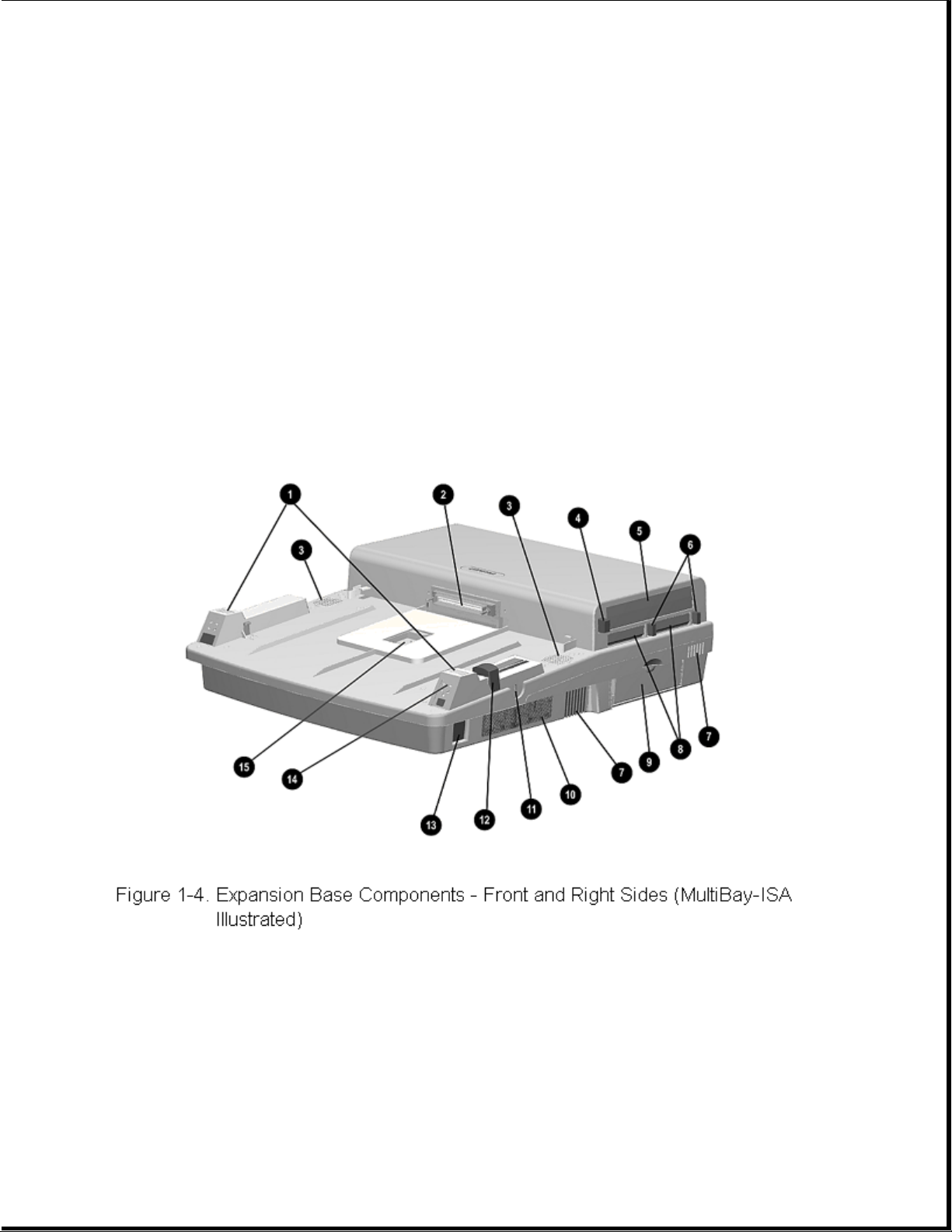
Chapter 1.6 MultiBay Expansion Base and MultiBay ISA Expansion Base Components
The external components on the front and right sides of the expansion base
are shown in Figure 1-4 and described in Table 1-7.
Table 1-7. Expansion Base Components - Front and Right Sides
===========================================================================
Item Description
===========================================================================
1 Monitor support cover slots
2 External options connector
3 Stereo speakers (MultiBay Expansion Base model)
 Loading...