


. . . . . . . . . . . . . . . . . . . . . . . . . . . . . . . . . . . . .
Notice
The information in this guide is subject to change without notice.
COMPAQ COMPUTER CORPORATION SHALL NOT BE LIABLE FOR TECHNICAL OR EDITORIAL ERRORS OR OMISSIONS CONTAINED HEREIN; NOR FOR INCIDENTAL OR CONSEQUENTIAL DAMAGES RESULTING FROM THE FURNISHING, PERFORMANCE, OR USE OF THIS MATERIAL.
This guide contains information protected by copyright. No part of this guide may be photocopied or reproduced in any form without prior written consent from Compaq Computer Corporation.
© 1997 Compaq Computer Corporation. All rights reserved. Printed in the U.S.A.
Compaq and LTE are registered in the U. S. Patent and Trademark Office.
Armada is a trademark of Compaq Computer Corporation.
Microsoft, MS-DOS, and Windows are registered trademarks of Microsoft Corporation.
The software described in this guide is furnished under a license agreement or nondisclosure agreement. The software may be used or copied only in accordance with the terms of the agreement.
Product names mentioned herein may be trademarks and/or registered trademarks of their respective companies.
Maintenance and Service Guide
Compaq ArmadaStation
Compaq Armada MiniStation E
Compaq Armada MiniStation EX
Compaq Armada 7000 Family of Personal Computers
First Edition August 1997
Documentation Part Number 272412-001
Spare Part Number 296391-001
Compaq Computer Corporation

. . . . . . . . . . . . . . . . . . . . . . . . . . . . . . . . . . . . .
Contents
Preface
Symbols.............................................................................................................. |
ix |
Technician Notes ............................................................................................... |
ix |
Serial Number ..................................................................................................... |
x |
Locating Additional Information........................................................................ |
x |
Chapter 1
Product Description
1.1 |
ArmadaStation Features............................................................................ |
1-1 |
1.2 |
ArmadaStation Components..................................................................... |
1-4 |
Activity Lights............................................................................................. |
1-8 |
|
MultiBay ...................................................................................................... |
1-8 |
|
Half-Height Bay .......................................................................................... |
1-8 |
|
Security Lock............................................................................................... |
1-9 |
|
PC Card Slots .............................................................................................. |
1-9 |
|
Regional Modem and Ethernet Differences .............................................. |
1-10 |
|
PCI and ISA Expansion Boards ................................................................ |
1-10 |
|
1.3 |
Armada MiniStation Features................................................................. |
1-11 |
1.4 |
Armada MiniStation Components .......................................................... |
1-13 |
Activity Lights........................................................................................... |
1-16 |
|
MultiBay .................................................................................................... |
1-16 |
|
Security Lock............................................................................................. |
1-16 |
|
PC Card Slots ............................................................................................ |
1-17 |
|
Regional Modem and Ethernet Differences .............................................. |
1-17 |
|
Chapter 2
Troubleshooting
Before Replacing Parts .................................................................................... |
2-1 |
Solving Docking and Undocking Problems................................................ |
2-2 |
Solving Expansion Board Problems............................................................ |
2-3 |
Solving Network Problems ......................................................................... |
2-3 |
Chapter 3
Illustrated Parts Catalog
3.1 |
ArmadaStation Components..................................................................... |
3-2 |
3.2 |
Miscellaneous Base Plastics Kit Components.......................................... |
3-4 |
3.3 |
Miscellaneous Base Hardware Kit Components ...................................... |
3-5 |
3.4 |
Miscellaneous Cable Kits ......................................................................... |
3-6 |
3.5 |
Miscellaneous Cable Kit Components ..................................................... |
3-8 |
3.6 |
Miscellaneous ........................................................................................... |
3-9 |
3.7 |
Documentation.......................................................................................... |
3-9 |
3.8 |
Armada MiniStation Components .......................................................... |
3-10 |
Contents v

. . . . . . . . . . . . . . . . . . . . . . . . . . . . . . . . . . . . .
3.9 |
Miscellaneous Enclosures Kit Components ........................................... |
3-12 |
3.10 |
Miscellaneous Plastics Kit Components .............................................. |
3-13 |
3.11 |
MultiBay/PC Card Assembly ............................................................... |
3-14 |
3.12 |
ArmadaStation and Armada MiniStation Options ............................... |
3-16 |
3.13 |
Miscellaneous ....................................................................................... |
3-18 |
3.14 |
Documentation...................................................................................... |
3-18 |
Chapter 4
Removal and Replacement Preliminaries
4.1 Electrostatic Discharge ............................................................................. |
4-1 |
Generating Static ......................................................................................... |
4-1 |
Preventing Electrostatic Damage to Equipment ......................................... |
4-2 |
Preventing Damage to Drives ..................................................................... |
4-2 |
Grounding Methods .................................................................................... |
4-3 |
Grounding Workstations ............................................................................. |
4-3 |
Grounding Equipment ................................................................................. |
4-4 |
Recommended Materials and Equipment ................................................... |
4-4 |
4.2 Service Considerations ............................................................................. |
4-5 |
Tool and Software Requirements................................................................ |
4-5 |
Screws.......................................................................................................... |
4-5 |
Cables and Connectors ................................................................................ |
4-6 |
Plastic Parts ................................................................................................. |
4-6 |
Chapter 5
ArmadaStation Removal and Replacement Procedures
5.1 |
Serial Number ........................................................................................... |
5-1 |
5.2 |
Disassembly Sequence Chart ................................................................... |
5-2 |
5.3 |
Preparing the ArmadaStation for Disassembly ........................................ |
5-3 |
5.4 |
External Components ............................................................................... |
5-4 |
Compaq Logo .............................................................................................. |
5-4 |
|
ArmadaStation Feet..................................................................................... |
5-5 |
|
Alignment Tray Assembly .......................................................................... |
5-6 |
|
5.5 |
Rear Panel Assembly................................................................................ |
5-8 |
5.6 |
Upper Case Assembly ............................................................................ |
5-11 |
5.7 |
Drive Cage Shield................................................................................... |
5-14 |
5.8 |
Half-Height Bays .................................................................................... |
5-16 |
Half-Height Drives .................................................................................... |
5-16 |
|
Half-Height MultiBay Adapters................................................................ |
5-22 |
|
5.9 |
I/O Assembly .......................................................................................... |
5-31 |
5.10 Top Brace.............................................................................................. |
5-35 |
|
5.11 Left Speaker Assembly......................................................................... |
5-38 |
|
5.12 |
Control Panel Cable.............................................................................. |
5-39 |
5.13 Control Panel Assembly ....................................................................... |
5-40 |
|
vi Contents

. . . . . . . . . . . . . . . . . . . . . . . . . . . . . . . . . . . . .
5.14 |
Expansion Boards ................................................................................. |
5-50 |
5.15 |
Mechanism Assembly........................................................................... |
5-52 |
5.16 |
Power Supply........................................................................................ |
5-55 |
5.17 |
Backplane Assembly............................................................................. |
5-57 |
5.18 |
Expansion Card Cage ........................................................................... |
5-59 |
Chapter 6
Armada MiniStation Removal and Replacement Procedures
6.1 |
Serial Number ........................................................................................... |
6-1 |
6.2 |
Disassembly Sequence Chart.................................................................... |
6-2 |
6.3 |
Preparing the Armada MiniStation for Disassembly ............................... |
6-3 |
6.4 |
External Components................................................................................ |
6-4 |
Compaq Logo .............................................................................................. |
6-4 |
|
Armada MiniStation Feet ............................................................................ |
6-5 |
|
6.5 |
Enclosure Cover........................................................................................ |
6-6 |
6.6 |
Module Assembly ..................................................................................... |
6-7 |
6.7 |
Power Supply .......................................................................................... |
6-11 |
6.9 |
MultiBay/PC Card Assembly ................................................................. |
6-12 |
Chapter 7
Specifications
7.1 |
ArmadaStation Physical and Environmental Specifications.................... |
7-1 |
7.2 |
Armada MiniStation Physical and Environmental Specifications ........... |
7-2 |
Appendix A |
|
Connector Pin Assignments ............................................................................... |
A-1 |
Appendix B |
|
Power Cord Set Requirements |
|
3-Conductor Power Cord Set.......................................................................... |
B-1 |
General Requirements ................................................................................ |
B-1 |
Country-Specific Requirements ................................................................. |
B-2 |
Notes ........................................................................................................... |
B-2 |
Index ............................................................................................................................ |
I-1 |
Contents vii

. . . . . . . . . . . . . . . . . . . . . . . . . . . . . . . . . . . . .
Preface
This Maintenance and Service Guide is a troubleshooting guide that can be used for reference when servicing the Compaq ArmadaStation and Armada MiniStation E and EX.
Compaq Computer Corporation reserves the right to make changes to the Compaq ArmadaStation and Armada MiniStation E and EX without notice.
Additional information is available on the Compaq ArmadaStation and Armada MiniStation E and EX Illustrated Parts Map. Information for the Compaq Armada 7700 Family of Personal Computers is available in the Compaq Armada 7700 Family of Personal Computers Maintenance and Service Guide and Illustrated Parts Map.
Symbols
The following words and symbols mark special messages throughout this guide:
! |
WARNING: Text set off in this manner indicates that failure to follow directions in the |
warning could result in bodily harm or loss of life. |
|
|
|
|
CAUTION: Text set off in this manner indicates that failure to follow directions in the |
|
caution could result in damage to equipment or loss of information. |
|
|
IMPORTANT: Text set off in this manner presents clarifying information or specific instructions.
NOTE: Text set off in this manner presents commentary, sidelights, or interesting points of information.
Technician Notes
! |
WARNING: Only authorized technicians trained by Compaq should attempt to repair this |
equipment. All troubleshooting and repair procedures are detailed to allow only |
|
|
subassembly/module level repair. Because of the complexity of the individual boards and |
|
subassemblies, no one should attempt to make repairs at the component level or to |
|
make modifications to any printed wiring board. Improper repairs can create a safety |
|
hazard. Any indication of component replacement or printed wiring board modifications |
|
may void any warranty or exchange allowances. |
|
|
! |
WARNING: The computer is designed to be electrically grounded. To ensure proper |
operation, plug the AC power cord into a properly grounded electrical outlet only. |
|
|
|
|
CAUTION: To properly ventilate your system, you must provide at least 3 inches |
|
(7.62 cm) of clearance on the front and back of the computer. |
|
|
Preface ix

. . . . . . . . . . . . . . . . . . . . . . . . . . . . . . . . . . . . .
Serial Number
When requesting information or ordering spare parts, provide the ArmadaStation or Armada MiniStation serial number. The ArmadaStation serial number is located on the right side below the PCI/ISA expansion slots; the Armada MiniStation serial number is located on the left side above the power button.
Locating Additional Information
The following documentation is available to support the ArmadaStation and Armada MiniStation:
■Compaq ArmadaStation documentation set
■Compaq Armada MiniStation documentation set
■Service training guides
■Compaq Service Advisories and Bulletins
■Compaq QuickFind
■Compaq Service Quick Reference Guide
■Compaq ArmadaStation and Armada MiniStation E and EX Maintenance and Service Guide
■Compaq ArmadaStation and Armada MiniStation E and EX Illustrated Parts Map
■Compaq Armada 7700 Family of Personal Computers Maintenance and Service Guide
■Compaq Armada 7700 Family of Personal Computers Illustrated Parts Map
x Preface
. . . . . . . . . . . . . . . . . . . . . . . . . . . . . . . . . . . . .
Chapter 1
Product Description
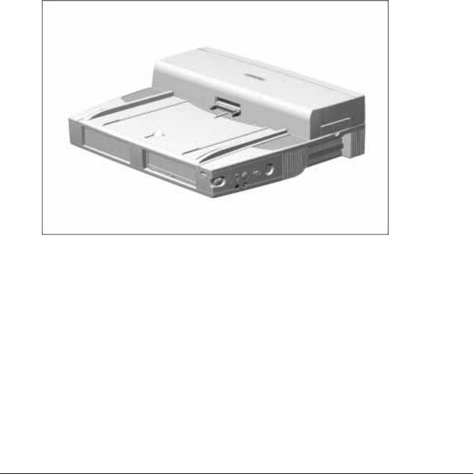
1.1 ArmadaStation Features
The Compaq ArmadaStation provides fully integrated desktop capabilities for the Compaq Armada 7000 Family of Personal Computers. The ArmadaStation eliminates the need to disconnect external devices when you remove the computer.
Figure 1-1. Compaq ArmadaStation
Introduction 1-1

. . . . . . . . . . . . . . . . . . . . . . . . . . . . . . . . . . . . .
The ArmadaStation provides a MultiBay device bay, a half-height device bay, two PC Card slots, integrated Ethernet, integrated stereo speakers, modem connections, computer I/O port replication, and connections for up to two PCI or ISA expansion boards. When the computer is docked in the ArmadaStation, the total system functionality includes:
■ Support for up to three MultiBay devices simultaneously
■ Overall system support for up to four hard drives* or two diskette drives
■ Up to three CD-ROM drives installed as follows:
– Three CD-ROM drives: The two drives in the ArmadaStation must be used for
*
data; the CD-ROM drive in the computer can then be used for audio or data.
– Two CD-ROM drives: You can have one drive in the ArmadaStation and one in the computer; either drive can be data or audio. If both drives are in the ArmadaStation, they must be for data only.*
– One CD-ROM drive: The drive can be either data or audio and in either the
*
computer or ArmadaStation.
■Two PC Card slots
■Overall system support for up to four PC cards
■Charging of up to four battery packs*
■Any combination of two 32-bit PCI and 16or 8-bit ISA expansion boards
*An Armada 7000 Half-Height MultiBay Adapter must be installed in the ArmadaStation to support up to four hard drives or battery packs, or three CD-ROM drives or MultiBay devices.
1-2 Introduction

. . . . . . . . . . . . . . . . . . . . . . . . . . . . . . . . . . . . .
The ArmadaStation also provides a variety of external equipment connectors. The following connectors are located on the ArmadaStation:
■Serial port
■Parallel port
■External mouse port
■External keyboard port
■External CRT port for resolutions up to 1280 × 1024
■RJ-11 modem jack (North America, Latin America, Japan, and Hong Kong modem models)
■25-pin modem connector (Europe, Middle East, Africa, and Asia Pacific modem models)
■Ethernet RJ-45 jack
■Ethernet BNC connector (Europe, Middle East, Africa, and Asia Pacific models)
■Two PC Card slots
■MIDI/joystick port
■Headphones out
■Infrared interface for IrDA wireless operations
■Infrared transceiver port
■Stereo speakers
■Stereo line-in, line-out
■Microphone out
Introduction 1-3
. . . . . . . . . . . . . . . . . . . . . . . . . . . . . . . . . . . . .
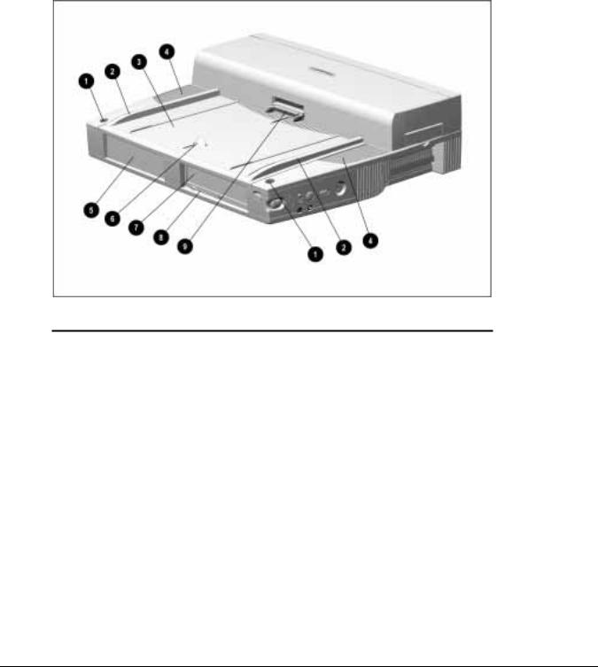
1.2 ArmadaStation Components
The external components on the top, front, and right side of the ArmadaStation are shown in Figure 1-2 and described in Table 1-1.
Figure 1-2. ArmadaStation Components: Top, Front, and Right Side
|
Table 1-1 |
|
ArmadaStation Components: Top, Front, and Right Side |
|
|
Item |
Description |
|
|
1 |
Monitor support cover slots (2) |
|
|
2 |
Alignment guides (2) |
|
|
3 |
Alignment tray |
|
|
4 |
Stereo speakers (2) |
|
|
5 |
Half-height bay |
|
|
6 |
Docking latch |
|
|
7 |
MultiBay |
|
|
8 |
MultiBay device release button |
|
|
9 |
Docking connector |
|
|
1-4 Introduction

. . . . . . . . . . . . . . . . . . . . . . . . . . . . . . . . . . . . .
Additional components on the front and right sides of the ArmadaStation are shown in Figure 1-3 and described in Table 1-2.
Figure 1-3. ArmadaStation Components: Front and Right Sides
|
Table 1-2 |
|
|
ArmadaStation Components: Front and Right Sides |
|
|
|
|
Item |
Description |
|
|
|
|
1 |
MultiBay activity light |
|
|
|
|
2 |
Suspend button |
|
|
|
|
3 |
Power/suspend light |
|
|
|
|
4 |
Computer eject button |
|
|
|
|
5 |
Infrared port |
|
|
|
|
6 |
Volume control |
|
|
|
|
7 |
Mute button |
|
|
|
|
8 |
Power button |
|
|
|
|
9 |
Keylock |
|
|
|
|
10 |
Serial number |
|
|
|
|
11 |
PCI/ISA expansion slots |
|
|
|
|
12 |
PC Card slots |
|
|
|
|
13 |
PC Card security post |
|
|
|
|
Introduction 1-5

. . . . . . . . . . . . . . . . . . . . . . . . . . . . . . . . . . . . .
The components on the rear panel and left side of the ArmadaStation are shown in Figure 1-4 and described in Table 1-3.
Figure 1-4. ArmadaStation Components: Rear Panel and Left Side
|
Table 1-3 |
|
|
ArmadaStation Components: Rear Panel and Left Side |
|
Item |
Description |
|
|
|
|
1 |
Rear panel release latch |
|
|
|
|
2 |
Security u-bolt |
|
|
|
|
3 |
Security cable slot |
|
|
|
|
4 |
Voltage selector switch |
|
|
|
|
5 |
Fan |
|
|
|
|
6 |
Audio bass port |
|
|
|
|
1-6 Introduction

. . . . . . . . . . . . . . . . . . . . . . . . . . . . . . . . . . . . .
The external connectors on the right side and rear panel of the ArmadaStation are shown in Figure 1-5 and described in Table 1-4.
Figure 1-5. ArmadaStation Connectors: Right Side and Rear Panel
|
Table 1-4 |
|
|
ArmadaStation Connectors: Right Side and Rear Panel |
|
|
|
|
Item |
Description |
|
|
|
|
1 |
Headphone jack |
|
|
|
|
2 |
Microphone jack |
|
|
|
|
3 |
Parallel connector |
|
|
|
|
4 |
External keyboard/mouse connectors |
|
|
|
|
5 |
Serial connector |
|
|
|
|
6 |
External monitor connector |
|
|
|
|
7 |
Stereo line-out jack |
|
|
|
|
8 |
Stereo line-in jack |
|
|
|
|
9 |
Infrared transceiver connector |
|
|
|
|
10 |
MIDI/joystick connector |
|
|
|
|
11 |
RJ-11 jack (North America, Latin America, Japan, and Hong Kong modem models) |
|
|
|
|
12 |
25-pin connector (Europe, Middle East, Africa, and Asia Pacific modem models) |
|
|
|
|
13 |
BNC connector (Europe, Middle East, Africa, and Asia Pacific models) |
|
|
|
|
14 |
RJ-45 jack (all models) |
|
|
|
|
15 |
Power connector |
|
|
|
|
Introduction 1-7

. . . . . . . . . . . . . . . . . . . . . . . . . . . . . . . . . . . . .
Activity Lights
The ArmadaStation has two activity lights.
MultiBay Activity Light
The MultiBay activity light is located on the MultiBay. This light turns on when information from a removable drive inserted in the ArmadaStation MultiBay is accessed.
Power/Suspend Light
The power/suspend light is located on the front/right corner of the ArmadaStation and is visible from both the front and right side of the ArmadaStation. This light turns on when the system (computer and ArmadaStation) is turned on; this light blinks when the system is placed in Suspend.
MultiBay
The ArmadaStation features a MultiBay. This MultiBay, along with its release latch, is removable as a unit. The MultiBay is located in the front of the ArmadaStation base assembly and secured by the drive cages, drive cage shield, and upper case assembly. The MultiBay supports the same drives that are used in the computer MultiBay and can be used to charge batteries.
The ArmadaStation MultiBay supports the following devices:
■CD-ROM drive
■Second hard drive
■Second battery pack
■Diskette drive
Compaq LTE Elite and LTE 5000 hard drives that are configured for use as secondary drives can be used in the ArmadaStation MultiBay. A hard drive must be inserted in an Armada 7000 Hard Drive MultiBay Adapter before it can be inserted in a MultiBay.
The system (computer and ArmadaStation) must be turned off when inserting or removing a hard drive, diskette drive, or CD-ROM drive from the MultiBay. The system does not have to be turned off when inserting or removing a battery pack.
Half-Height Bay
The ArmadaStation features one standard half-height bay, which is located on the front of the ArmadaStation. The half-height bay supports any standard half-height drive or a half-height MultiBay adapter.
1-8 Introduction

. . . . . . . . . . . . . . . . . . . . . . . . . . . . . . . . . . . . .
Security Lock
The ArmadaStation features a security lock that allows all computer and ArmadaStation resources (hard drives, diskette drives, CD-ROM drives, PC Cards) to be secured to the system (computer and ArmadaStation). When the security lock is engaged, the computer cannot be undocked, and no drives or PC Cards can be removed from the system.
NOTE: The PC Card security post must first be put in place before the security lock will prevent PC Cards from being removed from the ArmadaStation.
PC Card Slots
The ArmadaStation has two PC Card slots. The slots support one of the following PC Card combinations:
■Two Type I or Type II PC Cards
■One Type III PC Card in the top slot and a Type I or Type II in the bottom slot. If a Type III PC Card is inserted in the bottom PC Card slot, no other PC Cards can be used.
The PC Card slot supports both 5-volt and 3.3-volt PC Cards in accordance with the PC Card Standard and the Exchangeable Card Architecture (ExCA) Specifications 1.10.
NOTE: Many cards on the market do not comply with PC Card specifications and, therefore, do not function properly in the computer. To assist in selecting compatible PC Card devices, Compaq provides a list of third-party cards that have been tested in Compaq products. To ensure compatibility, select a PC Card from the Compaq PC Card Solutions List. Call Compaq Reseller Support to have a copy of the list faxed to you.
The only serviceable part of the PC Card slots is the slot door. The rails and connectors are incorporated into the I/O board.
Introduction 1-9

. . . . . . . . . . . . . . . . . . . . . . . . . . . . . . . . . . . . .
Regional Modem and Ethernet Differences
The modem and Ethernet connectors found on the ArmadaStation vary by region. Refer to the following table for modem and Ethernet differences:
Table 1-5
ArmadaStation Regional Modem and Ethernet Differences
Countries |
Modem Connectors |
Ethernet Connectors |
||
|
|
25-Pin |
BNC Connector |
RJ-45 Jack |
|
RJ-11 Jack |
Connector |
(10Base2) |
(10BaseT) |
|
|
|
|
|
North America |
■ |
|
|
■ |
|
|
|
|
|
Latin America |
■ |
|
|
■ |
|
|
|
|
|
Hong Kong |
■ |
|
|
■ |
|
|
|
|
|
Japan |
■ |
|
|
■ |
|
|
|
|
|
Europe |
|
■ |
■ |
■ |
|
|
|
|
|
Africa |
|
■ |
■ |
■ |
|
|
|
|
|
Middle East |
|
■ |
■ |
■ |
|
|
|
|
|
Asia Pacific |
|
■ |
■ |
■ |
|
|
|
|
|
PCI and ISA Expansion Boards
The ArmadaStation provides connectors for up to two PCI or ISA expansion boards. Any combination of two of these expansion boards can be installed in the ArmadaStation.
1-10 Introduction

. . . . . . . . . . . . . . . . . . . . . . . . . . . . . . . . . . . . .
1.3 Armada MiniStation Features
The Compaq Armada MiniStation provides fully integrated desktop capabilities for the Compaq Armada 7000 Family of Personal Computers. The Armada MiniStation eliminates the need to disconnect external devices when you undock the computer from the Armada MiniStation.
Figure 1-6. Compaq Armada MiniStation
The Armada MiniStation is available in two models to provide expanded functionality. The Armada MiniStation E and EX models provide port replication, modem passthrough, and Ethernet features for the Armada 7000 Family of Personal Computers. The Armada MiniStation EX model provides one MultiBay device bay, a battery charging bay, and two PC Card slots.
Introduction 1-11

. . . . . . . . . . . . . . . . . . . . . . . . . . . . . . . . . . . . .
When the computer is docked in the Armada MiniStation, the total system functionality includes:
Table 1-6
Armada MiniStation E & EX System Functionality
|
Armada MiniStation E |
Armada MiniStation EX |
Pass-Through Connections |
|
|
|
|
|
Stereo line in |
■ |
■ |
|
|
|
Stereo line out |
■ |
■ |
|
|
|
Microphone |
■ |
■ |
|
|
|
Serial |
■ |
■ |
|
|
|
Parallel |
■ |
■ |
|
|
|
Monitor |
■ |
■ |
|
|
|
Modem |
■ |
■ |
|
|
|
Mouse |
■ |
■ |
|
|
|
Other Features |
|
|
|
|
|
Cable lock provision |
■ |
■ |
|
|
|
Integrated AC power |
■ |
■ |
|
|
|
Infrared transceiver connector |
■ |
■ |
|
|
|
Ethernet adapter |
■ |
■ |
|
|
|
Accidental undock protection |
■ |
■ |
|
|
|
MultiBay |
|
■ |
|
|
|
PC Card slots |
|
■ |
|
|
|
Battery charging bay |
|
■ |
|
|
|
Keylock provision for bays |
|
■ |
|
|
|
1-12 Introduction

. . . . . . . . . . . . . . . . . . . . . . . . . . . . . . . . . . . . .
1.4 Armada MiniStation Components
The external components on the top and right side of the Armada MiniStation are shown in Figure 1-7 and described in Table 1-7.
NOTE: The Armada MiniStation E does not contain a battery charging bay or MultiBay.
Figure 1-7. Armada MiniStation Components: Right Side
|
Table 1-7 |
|
|
Armada MiniStation Components: Top and Right Side |
|
Item |
Description |
|
|
|
|
1 |
Docking latch |
|
|
|
|
2 |
Battery charging light (Armada MiniStation EX only) |
|
|
|
|
3 |
Battery charging bay (Armada MiniStation EX only) |
|
|
|
|
4 |
Eject/keylock button (Armada MiniStation EX only) |
|
|
|
|
5 |
PC Card slots (Armada MiniStation EX only) |
|
|
|
|
6 |
Security cable slot |
|
|
|
|
7 |
Docking lever |
|
|
|
|
8 |
Docking connector |
|
|
|
|
Introduction 1-13
. . . . . . . . . . . . . . . . . . . . . . . . . . . . . . . . . . . . .
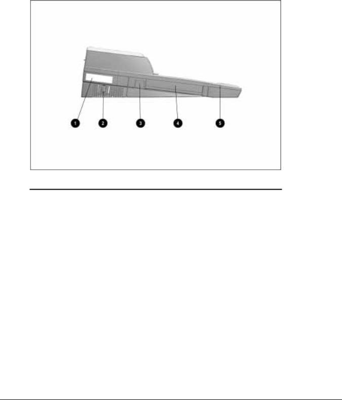
The components on the left side of the Armada MiniStation are shown in Figure 1-8 and described in Table 1-8.
Figure 1-8. Armada MiniStation Components: Left Side
|
Table 1-8 |
|
|
Armada MiniStation Components: Left Side |
|
Item |
Description |
|
|
|
|
1 |
Serial number |
|
|
|
|
2 |
Power button |
|
|
|
|
3 |
MultiBay eject button (Armada MiniStation EX only) |
|
|
|
|
4 |
MultiBay (Armada MiniStation EX only) |
|
|
|
|
5 |
MultiBay activity light (Armada MiniStation EX only) |
|
|
|
|
1-14 Introduction
. . . . . . . . . . . . . . . . . . . . . . . . . . . . . . . . . . . . .
The external components and connectors on the rear panel of the Armada MiniStation are shown in Figure 1-9 and described in Table 1-9.
Figure 1-9. Armada MiniStation Components: Rear Panel
Table 1-9
Armada MiniStation Components: Rear Panel
Item |
Description |
Item |
Description |
1 |
Stereo line-in jack |
9 |
Infrared transceiver connector |
|
|
|
|
2 |
Stereo line-out jack |
10 |
RJ-11 jack |
|
|
|
(North America, Japan, Latin America, and |
|
|
|
Hong Kong modem models) |
|
|
|
|
3 |
Microphone jack |
11 |
Parallel connector |
|
|
|
|
4 |
Serial connector |
12 |
External monitor connector |
|
|
|
|
5 |
External mouse connector |
13 |
25-pin connector |
|
|
|
(Europe, Middle East, Africa, and Asia |
|
|
|
Pacific modem models) |
|
|
|
|
6 |
External keyboard connector |
14 |
Fan |
|
|
|
|
7 |
RJ-45 jack (all models) |
15 |
Power connector |
|
|
|
|
8 |
BNC connector |
16 |
Voltage selector switch |
|
(Europe, Middle East, Africa, and Asia |
|
|
|
Pacific models) |
|
|
|
|
|
|
Introduction 1-15

. . . . . . . . . . . . . . . . . . . . . . . . . . . . . . . . . . . . .
Activity Lights
The ArmadaStation MiniStation EX has two activity lights.
MultiBay Light
The MultiBay light is located on the left side of the Armada MiniStation EX and is visible from both the top and left sides of the Armada MiniStation EX. This light turns on when information from a removable drive inserted in the MultiBay is accessed.
Battery Charging Light
The battery charging light is located on the right side of the Armada MiniStation EX and is visible from both the top and right sides of the Armada MiniStation EX. This light turns on when a battery is charging in the battery charging bay.
MultiBay
The MultiBay is located on the left side of the Armada MiniStation EX. The MultiBay supports the same MultiBay devices that are supported in the computer MultiBay and can be used to charge batteries. The Armada MiniStation EX MultiBay supports the following devices:
■CD-ROM drive
■Second hard drive
■Second battery pack
■Diskette drive
Compaq LTE Elite and LTE 5000 hard drives that are configured for use as secondary drives can be used in the Armada MiniStation EX MultiBay. A hard drive must be inserted in an Armada 7000 Hard Drive MultiBay Adapter before it can be inserted in a MultiBay.
The system (computer and Armada MiniStation EX) must be turned off when inserting or removing a hard drive, diskette drive, or CD-ROM drive from the MultiBay. The system does not have to be turned off when inserting or removing a battery pack.
Security Lock
The Armada MiniStation EX features a security lock that allows all computer and Armada MiniStation EX resources (hard drives, diskette drives, and CD-ROM drives) to be secured to the system (computer and Armada MiniStation EX). When the security lock is engaged, no drives can be removed from the computer or Armada
MiniStation EX.
NOTE: The Armada MiniStation EX security lock does not secure the computer. A Kensington lock can be used in the security cable slot to prevent the computer from being undocked.
1-16 Introduction

. . . . . . . . . . . . . . . . . . . . . . . . . . . . . . . . . . . . .
PC Card Slots
The ArmadaStation MiniStation EX has two PC Card slots. The slots support one of the following PC Card combinations:
■Two Type I or Type II PC Cards
■One Type III PC Card in the top slot and a Type I or Type II in the bottom slot. If a Type III PC Card is inserted in the bottom PC Card slot, no other PC Cards can be used.
The PC Card slot supports both 5-volt and 3.3-volt PC Cards in accordance with the PC Card Standard and the Exchangeable Card Architecture (ExCA) Specifications 1.10.
NOTE: Many cards on the market do not comply with PC Card specifications and, therefore, do not function properly in the computer. To assist in selecting compatible PC Card devices, Compaq provides a list of third-party cards that have been tested in Compaq products. To ensure compatibility, select a PC Card from the Compaq PC Card Solutions List. Call Compaq Reseller Support to have a copy of the list faxed to you.
Regional Modem and Ethernet Differences
The modem and Ethernet connectors found on the Armada MiniStation E and EX vary by region.
Table 1-10
Armada MiniStation E and EX Modem and Ethernet Differences
Countries |
Modem Connectors |
Ethernet Connectors |
||
|
|
25-Pin |
BNC Connector |
RJ-45 Jack |
|
RJ-11 Jack |
Connector |
(10Base2) |
(10BaseT) |
North America |
■ |
|
|
■ |
|
|
|
|
|
Latin America |
■ |
|
|
■ |
|
|
|
|
|
Hong Kong |
■ |
|
|
■ |
|
|
|
|
|
Japan |
■ |
|
|
■ |
|
|
|
|
|
Europe |
|
■ |
■ |
■ |
|
|
|
|
|
Africa |
|
■ |
■ |
■ |
|
|
|
|
|
Middle East |
|
■ |
■ |
■ |
|
|
|
|
|
Asia Pacific |
|
■ |
■ |
■ |
|
|
|
|
|
Introduction 1-17

. . . . . . . . . . . . . . . . . . . . . . . . . . . . . . . . . . . . .
Chapter 2
Troubleshooting
This chapter contains troubleshooting information for the ArmadaStation and Armada MiniStation. Information on how to identify and correct some common hardware, memory, and software problems is included. Troubleshooting information is covered on the following topics:
■Docking and undocking
■Expansion board
■Network
Since symptoms can appear to be similar, carefully match the symptoms of the computer malfunction against the problem description in the Troubleshooting tables to avoid a misdiagnosis.
Follow these guidelines when troubleshooting:
■Complete the recommended actions in the order in which they are given.
■When the problem is resolved, stop performing the troubleshooting steps and do not complete the remaining recommended actions.
■Refer to Chapters 5 and 6 for any recommended removal and replacement procedures.
■If the problem is intermittent, check the ArmadaStation or Armada MiniStation several times to verify that the problem is solved.
Before Replacing Parts
When troubleshooting a problem, check the following list for possible solutions before replacing parts:
■Verify that cables are connected properly to the suspected defective parts.
■Verify that all required device drivers are installed.
Troubleshooting 2-1

. . . . . . . . . . . . . . . . . . . . . . . . . . . . . . . . . . . . .
Solving Docking and Undocking Problems
The following table lists some common docking problems and recommended actions to take when they occur.
Table 2-1
Solving Docking and Undocking Problems
Problem |
Probable Cause |
Recommended Action(s) |
Cannot undock computer. |
The computer is using |
|
Windows NT and a software |
|
application is running. |
Exit all applications and turn off the system if you are using Windows NT. If the computer is using Windows 95, the system does not need to be turned off.
CAUTION: Do not force the Armada MiniStation docking lever forward. Forcing the docking lever forward can damage the locking mechanism.
|
Security cable is attached. |
Unlock security cable. |
|
PC Card cable is attached to |
Remove cable from PC Cards before |
|
the computer. |
undocking. |
|
|
|
The computer will not undock The ArmadaStation is locked. |
Unlock the ArmadaStation. |
|
from the ArmadaStation. |
|
|
|
|
|
|
No AC power. |
Release the computer from the docking |
|
|
mechanism by sliding the manual release |
|
|
lever to the right. |
|
|
|
The operating system does not support undocking while the computer is on or in Suspend.
Save all work, exit all applications and turn off the system before undocking.
The computer will not undock Connectors are tight. |
Grasp the computer and pull forward while |
|
from the Armada MiniStation. |
pulling forward on the Armada MiniStation |
|
|
|
docking lever. |
|
|
CAUTION: Do not force the Armada |
|
|
MiniStation docking lever forward. Forcing the |
|
|
docking lever forward can damage the |
|
|
locking mechanism. |
|
|
|
|
The Armada MiniStation |
Replace the docking lever. |
|
docking lever is defective. |
|
|
|
|
The computer is not properly docked or will not dock.
The computer is not properly |
Undock the computer and redock it. |
seated in the docking system. |
|
|
|
No AC power. |
Release the computer from the docking |
|
mechanism by sliding the ArmadaStation |
|
manual release lever to the right. |
|
|
2-2 Troubleshooting

. . . . . . . . . . . . . . . . . . . . . . . . . . . . . . . . . . . . . .
Solving Expansion Board Problems
The following table lists some common expansion board problems and recommended actions to take when they occur.
Table 2-2
Solving Expansion Board Problems
Problem |
Probable Cause |
Recommended Action(s) |
Expansion board does not |
Expansion board is not |
Reinstall the expansion board. |
work. |
properly seated. |
|
|
|
|
Expansion board is not |
Appropriate drivers for the |
recognized by the system. |
expansion board are not |
|
installed. |
Obtain the necessary drivers from the expansion board manufacturer.
Cannot remove hard drive |
ArmadaStation/Armada |
Unlock the ArmadaStation/Armada |
from ArmadaStation or |
MiniStation EX is locked. |
MiniStation EX and attempt to remove the |
Armada MiniStation EX |
|
hard drive. |
MultiBay. |
|
|
|
|
|
Solving Network Problems
This section provides guidelines for troubleshooting common Ethernet network problems. Refer to these guidelines when you have determined that the computer is not communicating with the network when docked in the ArmadaStation or Armada MiniStation. These guidelines do not discuss the process of debugging the network cabling.
The following are some common problems to check first. Refer to the table below for additional problems and solutions.
■Ensure that the cabling is securely attached to the ArmadaStation or Armada MiniStation. A loose cable is the most common cause of network problems. If the cable is loose, secure it and determine if the computer can communicate with the network.
■Determine whether the current computer or another computer has communicated with the network from the ArmadaStation or Armada MiniStation. If so, determine whether anything was added or changed that could have stopped the network interface from working.
■Run Diagnostics before installing the network drivers to verify that the network interface is working correctly.
Troubleshooting 2-3

. . . . . . . . . . . . . . . . . . . . . . . . . . . . . . . . . . . . .
Table 2-3
Solving Ethernet Network Problems
Problem |
Probable Cause |
Recommended Action(s) |
|
|
When turned on, the |
The computer is not |
Connect the computer to the Ethernet |
|
|
computer does not detect the |
connected to the Ethernet |
network. |
|
|
network. |
network. |
|
|
|
|
|
|
|
|
|
|
Suspend or Hibernation was |
Exit Suspend or Hibernation. |
|
|
|
initiated. |
Windows 95: Restart the system by clicking |
|
|
|
|
|
|
|
|
|
Start > Shut Down > Restart the Computer. |
|
|
|
|
Windows NT: Click Start > Shut Down. |
|
|
|
|
Power the computer back on. |
|
After installing the network |
The network driver fails to |
Ensure that network drivers are loaded and |
|
|
operating system, the |
load during initialization. |
that the drive path is correct. |
|
|
computer does not detect the |
|
|
|
|
|
If using a network interface |
Enable the parallel port. Restart the system. |
|
|
network interface. |
|
|||
card connected to a parallel |
Press F10 immediately when the cursor |
|
||
|
|
|
||
|
|
port, the port has been |
appears in the top right corner of the screen. |
|
|
|
disabled. |
|
|
|
|
Suspend or Hibernation was |
Exit Suspend or Hibernation. |
|
|
|
initiated. |
Windows 95: Restart the system by clicking |
|
|
|
|
|
|
|
|
|
Start > Shut Down > Restart the Computer. |
|
|
|
|
Windows NT: Click Start > Shut Down. Power |
|
|
|
|
the computer back on. |
|
|
|
|
|
|
Diagnostics reports a failure. |
The cable is not securely |
Ensure that the cable is securely connected to |
|
|
|
|
connected to the network |
the proper network connector on the Ethernet |
|
|
|
connector on the Ethernet |
network. |
|
|
|
network. |
|
|
|
|
|
|
|
There is a problem with the cable or device at the other end of the cable.
Ensure that the cable and device at the other end of the network connection are operating properly.
Possible hardware failure. |
Replace the Ethernet assembly. |
Diagnotics reports no errors, but the computer does not communicate with the network.
Network drivers are not |
Load the network drivers. |
loaded. |
Windows 95: Restart the system by clicking |
|
|
|
Start > Shut Down > Restart the Computer. |
|
Windows NT: Click Start > Shut Down. Power |
|
the computer back on. |
A network configuration error |
Contact the network administrator. |
may have occurred (i.e., *.ini, |
|
*.inf, *.nif, or CONFIG.SYS |
|
files may need to be modified). |
|
Suspend or Hibernation was |
Exit Suspend or Hibernation. |
initiated. |
Windows 95: Restart the system by clicking |
|
|
|
Start > Shut Down > Restart the Computer. |
|
Windows NT: Click Start > Shut Down. Power |
|
the computer back on. |
Continued
2-4 Troubleshooting

. . . . . . . . . . . . . . . . . . . . . . . . . . . . . . . . . . . . . .
Table 2-3 Continued
Problem |
Probable Cause |
Recommended Action(s) |
The computer stopped |
The computer does not detect |
Windows 95: Restart the system by clicking |
communicating with the |
network drivers. |
Start > Shut Down > Restart the Computer. |
network after exiting |
|
Windows NT: Click Start > Shut Down. Power |
Suspend. |
|
the computer back on. |
|
|
|
The computer stopped |
The cable is not securely |
Ensure that the cable is securely connected to |
communicating with the |
connected to the network |
the ArmadaStation/Armada MiniStation and |
network for no apparent |
connector on the Ethernet. |
the Ethernet network. |
reason. |
General network failure. |
Ensure that the network you are connected to |
|
|
is running and has not experienced problems |
|
|
that would prevent the connection. |
|
|
|
|
The files for the network |
Reinstall the network drivers. |
|
drivers have been corrupted. |
|
|
|
|
IMPORTANT: If the 100BaseT Ethernet upgrade module has been installed, remove it before returning the Ethernet module, ArmadaStation, or Armada MiniStation for replacement.
Troubleshooting 2-5

. . . . . . . . . . . . . . . . . . . . . . . . . . . . . . . . . . . . .
2-6 Troubleshooting

. . . . . . . . . . . . . . . . . . . . . . . . . . . . . . . . . . . . .
Chapter 3
Illustrated Parts Catalog
This chapter provides an illustrated parts breakdown and a reference for spare part numbers for the Compaq ArmadaStation and Armada MiniStation.
Illustrated Parts Catalog |
3-1 |
 Loading...