


 Loading...
Thank you for purchasing this Factory Service Manual CD/DVD from servicemanuals4u.com.
Please check out our eBay auctions for more great deals on Factory Service Manuals:
servicemanuals4u

Foreword
Notice
The information in this guide is subject to change without notice.
Compaq Computer Corporation shall not be liable for technical or editorial errors or omissions contained herein; nor for incidental or consequential damages resulting from the furnishing, performance, or use of this material.
This document contains proprietary information protected by copyright. No part of this document may be photocopied or reproduced in any form with out prior written consent from Compaq Computer Corporation.
Copyright 1986 by Compaq Computer Corporation.
All rights are reserved.
COMPAQ, COMPAQ PLUS and COMPAQ PORTABLE 286 are registered trademarks and COMPAQ PORTABLE II is a trademark of COMPAQ Computer Corporation.
The software described in this document is furnished under a license agreement of nondisclosure. The software may be used or copied only in accordance with the terms of the agreement. It is against the law to copy Microsoft BASIC or MS-DOS onto cassette tape, fixed disk drive, diskette, or any other medium for any purpose other than the purchaser's personal use.
Copyright 1981, 1982, 1983, 1984, 1985, and 1986 by Microsoft Corporation.
MS-DOS is a registered trademark of Microsoft Corporation.
MAINTENANCE AND SERVICE GUIDE
COMPAQ PORTABLE COMPUTER
COMPAQ PLUS PERSONAL COMPUTER
COMPAQ PORTABLE 286 PERSONAL COMPUTER
Second Edition (April 1986)
Assembly Number 102901-001
Binder Number 102900-001
Text Number 102973-001
Compaq Computer Corporation 90 Day Limited Warranty
Compaq Computer Corporation (Compaq) warrants the products that it manufactures to be free from defects in materials and workmanship for a period of 90 days from the date of purchase from Compaq or an Authorized COMPAQ Computer Dealer. This warranty is limited to the original purchaser (Purchaser) of the product and is not transferable.
During the 90 day (ninety day) warranty period, Compaq will repair or replace with new or refurbished parts, at its option, any defective parts at no additional charge, provided that the product is returned, shipping prepaid, to Compaq or an Authorized COMPAQ Computer Dealer. The Purchaser is responsible for insuring any product so returned and assumes the risk of loss during shipping. All replaced parts and products become the property of Compaq.
Dated proof of purchase must be provided by the Purchaser when requesting that warranty work be performed. The Purchaser may request information on how to obtain warranty service by contacting an Authorized COMPAQ Computer Dealer or writing to Compaq Computer Corporation for further information.

This limited warranty does not extend to any products that have been damaged as a result of accident, misuse, abuse, non Compaq modification, or as a result of service by anyone other than Compaq or an Authorized COMPAQ Computer Dealer.
Except as expressly set forth above, no other warranties are expressed or implied, including, but not limited to, any implied warranties of merchantability and fitness for a particular purpose, and Compaq expressly disclaims all warranties not stated herein in the event the product is not free from defects as warranted above, the purchaser's sole remedy shall be repair or replacement as provided above. Under no circumstances will Compaq be liable to the purchaser or any user for any damages, including any incidental or consequential damages, expenses, lost profits, lost savings, or other damages arising out of the use of or inability to use the product.
Some states do not allow the exclusion of limitation of incidental or consequential damages for consumer products, and some states do not allow limitations on how long an implied warranty lasts, so the above limitations or exclusions may not apply to you.
This warranty gives you specific legal rights, and you may also have other rights that vary from state to state.
>>>>>>>>>>>>>>>>>>>>>>>>>>>>>>>>>>>>>>><<<<<<<<<<<<<<<<<<<<<<<<<<<<<<<<<<<<<<<
WARNING
This equipment has been certified to comply with the limits for a Class B computing device, pursuant to Subpart J of Part 15 of FCC Rules. Only peripherals (computer input/output devices, terminals, printers, and so on.) certified to comply with the Class B limits may be attached to this computer. Operation with noncertified peripherals is likely to result in interference to radio and TV reception.
>>>>>>>>>>>>>>>>>>>>>>>>>>>>>>>>>>>>>>><<<<<<<<<<<<<<<<<<<<<<<<<<<<<<<<<<<<<<<
WARNING
This equipment generates, uses, and can radiate radio frequency energy. If not installed and used in accordance with the manufacturer's instructions, it may cause interference with radio and television reception. This equipment has been certified to comply with the limits for a Class B computing device, pursuant to Subpart J of Part 15 of FCC Rules, which are designed to provide reasonable protection against such interference. If this occurs, the user will be required to take whatever measures may be necessary to eliminate the interference. In attempting to do so, the user should:
o Reorient the receiving antenna.
oRelocate the computer with respect to the receiver with which it interferes.
oPlug the computer into a different AC outlet so that the computer and the receiver with which it interferes are on different branch circuits.

>>>>>>>>>>>>>>>>>>>>>>>>>>>>>>>>>>>>>>><<<<<<<<<<<<<<<<<<<<<<<<<<<<<<<<<<<<<<<
If necessary, the user should consult an Authorized COMPAQ Computer Dealer or any experienced radio/television technician for additional suggestions.
Compaq Computer Corporation requires that all peripheral devices be connected to this computer via shielded cables with metal RFI/EMI connector hoods.
Wire Type: Multipaired overall shielded; Belden #98xx; Alpha #54xx; or equivalent.
Connector Hood: RFI/EMI metal shield; AMP #745l7x-x; or equivalent.
It is important that the chassis ground of any peripheral device be connected to the computer chassis. An Alpha #1221 flat braided strap is sufficient. This strap is not necessary if the shielded cable connects the two chassis.
Preface
The Maintenance and Service Guide is a troubleshooting, maintenance, and repair guide that can be used as a reference when servicing the COMPAQ Portable Computer, the COMPAQ PLUS Personal Computer, and the COMPAQ PORTABLE 286 Personal Computer.
All troubleshooting and repair procedures are detailed to allow subassembly/ module level repair only.
>>>>>>>>>>>>>>>>>>>>>>>>>>>>>>>>>>>>>>><<<<<<<<<<<<<<<<<<<<<<<<<<<<<<<<<<<<<<<
CAUTION
Because of the complexity of the individual boards and subassemblies, Compaq Computer Corporation strongly recommends that you do not attempt to make field repairs at the component level. Indications of this may void any warranty or exchange allowances.
>>>>>>>>>>>>>>>>>>>>>>>>>>>>>>>>>>>>>>><<<<<<<<<<<<<<<<<<<<<<<<<<<<<<<<<<<<<<<
Summary of Text
The Maintenance and Service Guide contains the following eight chapters.
Chapter 1 "Operating and Performance Specifications" provides operating and performance specifications for the COMPAQ Portable, the COMPAQ PLUS, and the COMPAQ PORTABLE 286 Personal Computers.
Chapter 2 "Power On Self Test (POST)/Problem Isolation" describes the internal system diagnostics programs that are automatically executed when you turn on the system. A flowchart is provided for quick reference for identifying and correcting problems that may occur during the Power On Self Test procedure.
Chapter 3 "SETUP" describes how to configure the system and defines the system prompts.

Chapter 4 "DIAGNOSTIC Procedures" describes the use and function of the' COMPAQ DIAGNOSTIC Program Version 3. The text provides a detailed description of the various diagnostic routines and how to execute them.
Chapter 5 "Error Messages and Codes" lists and describes the Power On Self Test (POST) and DIAGNOSTICS Error Codes. It also provides required action for resolving each problem described by the corresponding error code.
Chapter 6 "Illustrated Parts Catalog" contains illustrated parts breakdowns, order numbers, and part names for the COMPAQ Portable, the COMPAQ PLUS, and the COMPAQ PORTABLE 286 Personal Computers.
Chapter 7 "Removal and Replacement Procedures" describes how to remove and replace subassemblies for the COMPAQ Portable, the COMPAQ PLUS, and the COMPAQ PORTABLE 286 Personal Computers.
Chapter 8 "Jumper Settings, Switch Settings, and Adjustments" provides detailed information for setting jumpers and switches. It also provides instructions for adjusting the video display unit and the diskette drive speed.
Required Tools and Supplies
To service the COMPAQ Portable, COMPAQ PLUS, and COMPAQ PORTABLE 286 Personal Computers, you need:
o1/4 inch slotted blade screwdriver (COMPAQ Portable and COMPAQ PLUS Personal Computers only)
o |
COMPAQ DIAGNOSTICS Diskette Version 3 (PN 102971-001 *) |
o |
Formatted Scratch Diskette(s) |
o |
Printer loopback plug 25 pin (PN 100755-001) |
o |
Serial loopback plug 25 pin (PN 100754-001) |
o |
9 pin serial loopback plug (PN 102999-001) |
o |
Torx T-15 screwdriver |
o |
Torx T-10 screwdriver |
o 1/4 inch nut driver |
|
o No. 2 Phillips screwdriver |
|
o |
5/16 inch Box end wrench |
Optional Tools are:
o |
Digital voltmeter |
||
o |
Memory |
chip |
(integrated circuit) insertion tool |
o |
Memory |
chip |
(integrated circuit) removal tool |

o |
Diskette |
drive |
signal extension cable (PN 100546-001) |
o |
Diskette |
drive |
power extension cable (PN 100545-001) |
oSpecial Service Tool Kit (PN 101089-001) containing:
-Power Supply socket adjustment tool
-T-10 socket
-3/16 inch socket
-5/16 inch adjustable socket
Additional Information
The following documentation and related software are available to support these and other COMPAQ computer products.
Associated Documentation:
o COMPAQ PORTABLE COMPUTER OPERATIONS GUIDE (PN 100001-001)
o COMPAQ PLUS PERSONAL COMPUTER OPERATIONS GUIDE (PN 100633-001 *)
o COMPAQ PORTABLE 286 PERSONAL COMPUTER OPERATIONS GUIDE (PN 101770-001 *) o AUTHORIZED DEALER GUIDE (PN 100003-001)
o MS-DOS VERSION 2 REFERENCE GUIDE (PN 100631-002 *) o MS-DOS VERSION 3 REFERENCE GUIDE (PN 102631-001 *) o BASIC VERSION 2 REFERENCE GUIDE (PN 100632-001 *) o BASIC VERSION 3 REFERENCE GUIDE (PN 102740-001)
o 80286 BASED PRODUCTS TECHNICAL REFERENCE GUIDE (PN 102786-001)
* Part number no longer available.

Chapter 1. Operating and Performance Specifications
Chapter 1.1 Introduction
This section provides operating and performance specifications for the COMPAQ Portable and the COMPAQ PLUS in Table 1-1, and the COMPAQ PORTABLE 286
in Table 1-2.
Specifications for the COMPAQ Portable and COMPAQ PLUS Personal Computer are:
o |
Electrical and mechanical |
o |
Environmental |
o |
Keyboard |
o |
Video display |
o |
360 Kbyte diskette drive |
o |
10 megabyte fixed disk drive |
o |
Power supply |
Specifications for the COMPAQ PORTABLE 286 Personal Computer are:
o |
Electrical and mechanical |
|
o |
Environmental |
|
o |
Keyboard |
|
o |
Video display |
|
o |
20 |
megabyte fixed disk drive |
o |
10 |
megabyte tape drive |
o |
1.2 |
megabyte diskette drive |
o |
360 |
Kbyte diskette drive |
o |
Power supply |
|
Table 1-1. COMPAQ Portable and COMPAQ PLUS Personal Computers Operating and Performance Specifications
==============================================================================
Electrical and Mechanical Specifications
------------------------------------------------------------------------------
Dimensions:
Height |
8.5 in. |
(215.9 mm) |
|
Depth |
16.0 |
in. (406.4 mm) |
|
Width |
20.0 |
in. (512.8 mm) |
|
Weight: |
|
|
|
With one diskette drive |
27.5 |
lb |
(12.5 kg) |
With two diskette drives |
30.5 |
lb |
(13.5 kg) |
With one diskette drive |
|
|
|
and one fixed disk drive |
31 lb (14 kg) |
||
Power Requirements: |
|
|
|
Line Voltage |
115 VAC |
|
|
Line Frequency |
60 Hz |
|
|
Power |
|
|
|
Current |
3 amps |
|
|

Power Cable: |
|
|
Length |
79 |
in. (2006.6 mm) |
Gauge |
18 |
AWG |
Environmental Requirements: |
|
|
Temperature: |
|
|
Operating |
50oF to 104oF (10oC to 40oC) |
|
Nonoperating |
32oF to 140oF (0oC to 60oC) |
|
Humidity: |
|
|
Operating |
20% to 80% (noncondensing) |
|
Nonoperating |
5% |
to 90% (noncondensing) |
------------------------------------------------------------------------------
Keyboard Specifications
------------------------------------------------------------------------------
Dimensions: |
|
|
Height |
1.5 in. (38.1 mm) |
|
Depth |
7.06 in. (179.3 mm) |
|
Width |
18.25 in. (463.6 mm) |
|
Number of Keys |
83 |
|
Keyboard Cable: |
|
|
Length |
72 |
in. (1828.8 mm) |
Gauge |
28 |
AWG |
------------------------------------------------------------------------------
Video Display Specifications
------------------------------------------------------------------------------
Display: |
|
|
|||
o |
Nine inch |
diagonal, 90 degree deflection |
|||
o |
High persistence green phosphor |
||||
o |
Etched surface to reduce glare |
||||
o |
80 |
character by 25 |
line screen |
||
o |
40 |
character by 25 |
line screen |
||
o |
640 |
x 200 |
dot resolution, graphics |
||
o |
320 |
x 200 |
dot resolution, graphics |
||
o |
720 |
x 350 |
dot resolution, text |
||
------------------------------------------------------------------------------
360 Kbyte Diskette Drive Specifications
------------------------------------------------------------------------------
Dimensions: |
|
|
|
|
Height |
1.625 in. (40.625 mm) |
|||
Depth |
8.29 |
in. (210.6 |
mm) |
|
Width |
5.88 |
in. (149.4 |
mm) |
|
Weight |
3.2 |
lb (1.45 kg) |
|
|
Data Transfer Rate |
250 |
Kb/s |
|
|
Media |
48 TPI Double Sided Double Density Diskettes |
|||
Number of Tracks |
40 |
|
|
|
Tracks per Inch |
48 |
|
|
|
------------------------------------------------------------------------------
10 Megabyte Fixed Disk Drive Specifications

------------------------------------------------------------------------------
Dimensions: |
|
Height |
1.69 in. (4.33 cm) |
Width |
5.875 in. (14.6875 cm) |
Depth |
8.25 in. (20.625 cm) |
Weight |
3.5 lb (1.575 kg) |
Media |
Fixed plated media |
Tracks per Inch |
600 |
Number of Cylinders |
305 |
Data Transfer Rate |
5 Mb/s |
Average Access Time |
105 ms |
------------------------------------------------------------------------------
Power Supply Specifications
------------------------------------------------------------------------------
Input Requirements:
AC Voltage RMS: |
|
|
|
Domestic |
102 |
- 132 |
VAC |
International |
204 |
- 264 |
VAC |
Line Frequency |
47 to 62 Hz |
||
Line Voltage |
120 |
VAC, 60 Hz |
|
Current |
2 amps maximum at input |
||
|
(3 amps depending on fuse rating) |
||
------------------------------------------------------------------------------
VDC Output: |
Nominal |
Current |
Current |
Regulation |
|
Voltage |
Amps |
Amps |
Tolerance |
|
VDC |
Minimum |
Maximum * |
Percent |
------------------------------------------------------------------------------
+ 5.0 |
2.0 |
10.0 |
5 |
|
- 5.0 |
0.0 |
0.5 |
5 |
|
+ |
12.0 |
1.0 |
5.0 |
5 |
- |
12.0 |
0.0 |
0.5 |
5 |
------------------------------------------------------------------------------
*These values are maximum values based on nominal operating conditions for temperature, line voltage, line frequency, and altitude.
==============================================================================
Table 1-2. COMPAQ PORTABLE 286 Personal Computer Operating and Performance Specifications
==============================================================================
Electrical and Mechanical Specifications
------------------------------------------------------------------------------
Dimensions:
Height |
8.5 in. (215.9 mm) |
|
Depth |
16 |
in. (406.4 mm) |
Width |
20 |
in. (508.0 mm) |
Weight: |
|
|
Model 1 |
30 |
lb (13.5 kg) |
Model 2 |
33 |
lb (15.0 kg) |
Model 3 |
34 |
lb (15.4 kg) |
Power Requirements: |
|
|
Line Voltage |
115 VAC |
|
Line Frequency |
60 |
Hz |

Power |
|
|
Current |
4 amps |
|
Power Cable: |
|
|
Length |
72 |
in. (1828.8 mm) |
Gauge |
18 |
AWG |
------------------------------------------------------------------------------
Environmental Requirements
------------------------------------------------------------------------------
Temperature:
Operating |
50oF to 104oF |
(10oC to 40oC) |
Nonoperating |
32oF to 140oF |
(0oC to 60oC) |
Humidity: |
|
|
Operating |
20% to 80% (noncondensing) |
|
Nonoperating |
5% to 90% (noncondensing) |
|
------------------------------------------------------------------------------
Keyboard Specifications
------------------------------------------------------------------------------
Dimensions: |
|
|
Height |
1.5 in. (38.1 mm) |
|
Depth |
7.06 in. (179.3 mm) |
|
Width |
18.25 in. (436.6 mm) |
|
Number of Keys |
84 |
|
Keyboard Cable: |
|
|
Length |
72 |
in. (1828.8 mm) |
Gauge |
28 |
AWG |
------------------------------------------------------------------------------
Video Display Specifications
------------------------------------------------------------------------------
Display: |
|
|
|||
o |
Nine inch |
diagonal, 90 degree deflection |
|||
o |
High persistence green phosphor |
||||
o |
Etched surface to reduce glare |
||||
o |
80 |
character by 25 |
line screen |
||
o |
40 |
character by 25 |
line screen |
||
o |
640 |
x 200 |
dot resolution, graphics |
||
o |
320 |
x 200 |
dot resolution, graphics |
||
o |
720 |
x 350 |
dot resolution, text |
||
------------------------------------------------------------------------------
20 Megabyte Fixed Disk Drive Specifications
------------------------------------------------------------------------------
Dimensions: |
|
|
Height |
1.7 |
in. (4.33 cm) |
Depth |
4.1 |
in. (10.41 cm) |
Width |
5.75 in. (14.61 cm) |
|
Weight |
1.8 |
lb (0.8 kg) |
Media |
Fixed plated media |
|
Number of Data Heads |
4 |
|
Number of Cylinders |
615 |
Average Access Time |
105 ms |
(maximum) |
Data Transfer Rate |
5 Mb/s |
|
------------------------------------------------------------------------------
10 Megabyte Tape Drive Specifications
------------------------------------------------------------------------------
Dimensions: |
|
Height |
1.65 in. (4.29 cm) |
Depth |
8 in. (20 cm) |
Width |
5.65 in. (14.76 cm) |
Weight |
1.7 lb (0.765 kg) |
Media |
DC 1000 Manufactured by 3M Corporation or |
|
equivalent |
------------------------------------------------------------------------------
1.2 Megabyte Diskette Drive Specifications
------------------------------------------------------------------------------
Dimensions: |
|
|
|
|
|
Height |
1.65 |
in. |
(4.29 cm) |
||
Depth |
8.25 |
in. |
(20.625 cm) |
||
Width |
5.88 |
in. |
(14.7 cm) |
||
Weight |
3.2 lb |
(1.44 kg) |
|||
Media |
96 |
and |
48 TPI Double Sided High Density Diskettes |
||
Tracks per Inch |
96 |
|
|
|
|
Number of Tracks |
80 |
(When |
formatted with MS-DOS) |
||
Data Transfer Rate |
300/500 Kb/s |
||||
------------------------------------------------------------------------------
360 Kbyte Diskette Drive Specifications
------------------------------------------------------------------------------
Dimensions: |
|
|
|
|
Height |
1.60 in. (4.0625 cm) |
|||
Depth |
8.0 |
in. (20.625 cm) |
||
Width |
5.8 |
in. (14.7 cm) |
||
Weight |
3.2 |
lb |
(1.44 kg) |
|
Media |
40 |
TPI Double Sided Double Density Diskettes |
||
Tracks per Inch |
48 |
|
|
|
Number of Tracks |
40 |
(When formatted with MS-DOS) |
||
Data Transfer Rate |
250 |
Kb/s |
||
Power supply specifications: |
|
|
|
|
Input Requirements: |
|
|
|
|
Line |
102 |
to |
132 VAC, single phase |
|
Voltage |
180 |
to |
264 VAC, single phase |
|
Line Fuse |
3 amps |
250V fuse for 115 VAC operation, |
||
|
2.5 |
amps for 220 VAC operation |
||
Line Frequency |
47 |
to 62 Hz |
||

Cooling |
Forced air provided by 16 VDC fan |
Current |
2 amps, maximum at input voltage of 120 VAC, |
|
60 Hz |
------------------------------------------------------------------------------
VDC Output: |
Nominal |
Current |
Current |
Regulation |
|
Voltage |
Amps |
Amps |
Tolerance |
|
VDC |
Minimum |
Maximum * |
Percent |
------------------------------------------------------------------------------
+ 5.0 |
1.5 |
15.0 |
2 |
- 5.0 |
0.0 |
0.5 |
5 |
+ 12.25 |
1.0 |
5.0 |
2 |
+ 12.25 |
0.0 |
1.5 |
3 |
(internal monitor) |
|
|
|
- 12.0 |
0.0 |
1.0 |
5 |
------------------------------------------------------------------------------
* These values are maximum values based on nominal operating conditions for temperature, line voltage, line frequency, and altitude.
==============================================================================

Chapter 2. Power On Self Tests (POST)/Problem Isolation
Chapter 2.1 Introduction
This section provides a list of assemblies checked by the Power On Self Test (POST) and a brief description of the types of error codes. The section also contains preliminary steps to problem isolation of an error condition and a problem isolation flowchart for quick reference.
Chapter 2.2 Power On Self Test (POST)
A series of diagnostic tests automatically run on every COMPAQ Personal Computer system when the system is turned on. These tests are called the Power On Self Test (POST).
POST checks the following assemblies to ensure that the computer system is functioning properly:
o |
Keyboard |
o |
Power Supply |
o |
System Board |
o |
Video Display Controller Board |
o |
Fixed Disk Drive Controller Board |
o |
Diskette/Printer Controller Board |
o |
Asynchronous Communications/Clock Board |
o |
System Board |
o |
Memory |
POST also detects the type(s) of mass storage device(s) installed in the computer.
When the computer is turned on, POST automatically starts and runs. If POST finds an error in the system, error codes (in the form of beeps) are heard or error codes (numbers) are visible on the monitor. See Chapter 5, "Error Messages and Codes," for an explanation of error codes.
Chapter 2.3 Preliminary Steps to Problem Isolation
If you encounter an error condition, complete the following preliminary steps before starting problem isolation.
1.Place the ON/OFF switch in the OFF position.
2.Disconnect the signal cables of any peripheral devices (printers, modems, and so on) from the computer.
3.Remove the upper access panel and board slots access cover (see Chapter 7, "Removal and Replacement Procedures.")
When the upper access panel is removed, the system LED, located on the
system board between the expansion slots, is visible.
4.Remove all non COMPAQ options (board, drives, and so on) from the computer.
5.Install a loopback plug connector in the parallel port and the asynchronous port and any other location that requires a loopback plug.
NOTE: If you want to test your printer during the printer test or to log errors to a printer, reconnect the printer now.
6.Verify that the AC power cable is connected to a usable power outlet.
7.Insert the latest version of the COMPAQ DIAGNOSTICS Program diskette into drive A and close the drive door.
8.Place the ON/OFF switch in the ON position. See Chapter 4, "DIAGNOSTIC Procedures," for detailed information on problem isolation.
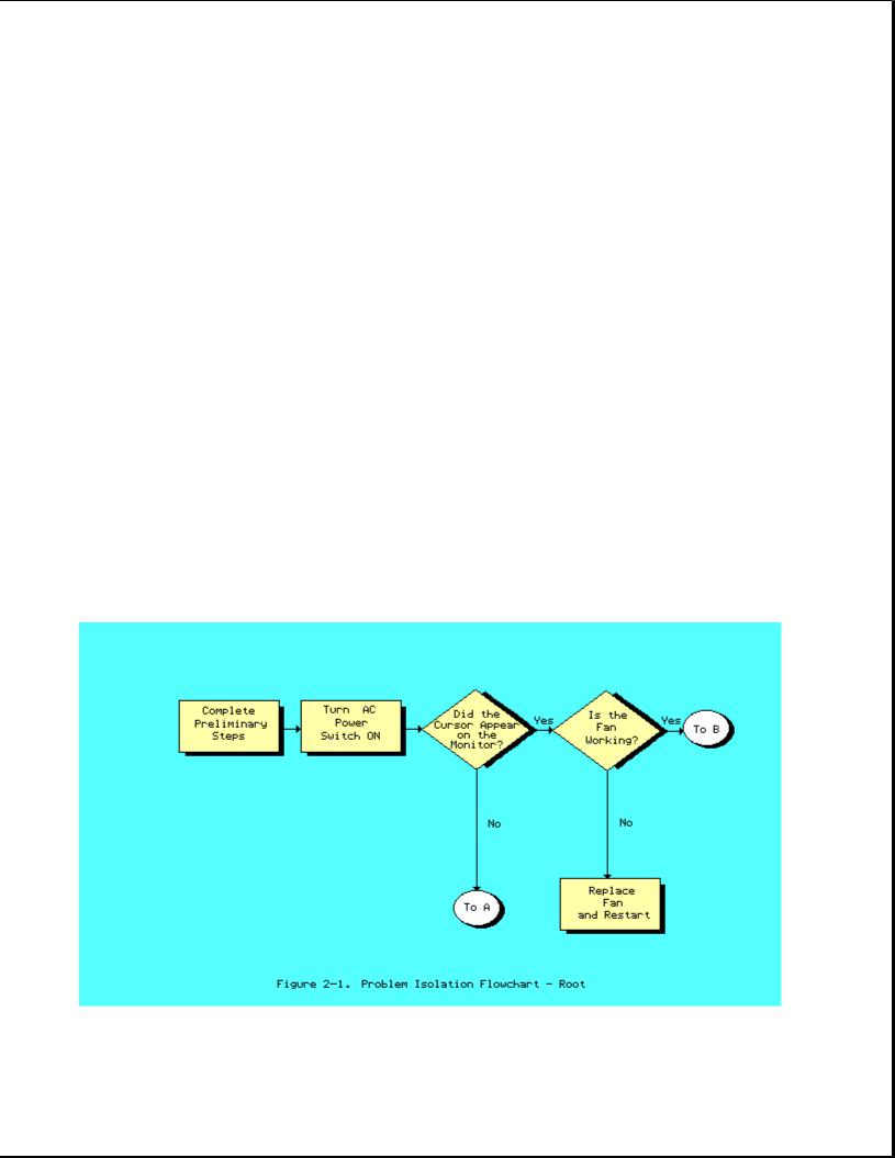
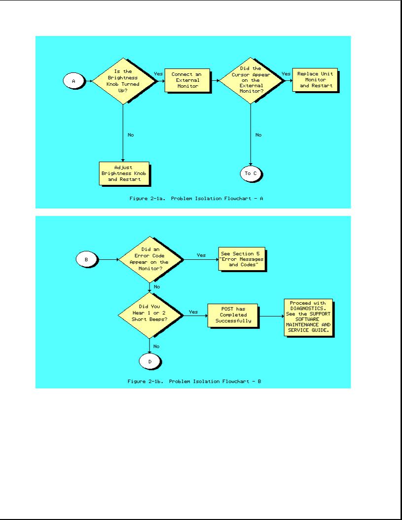
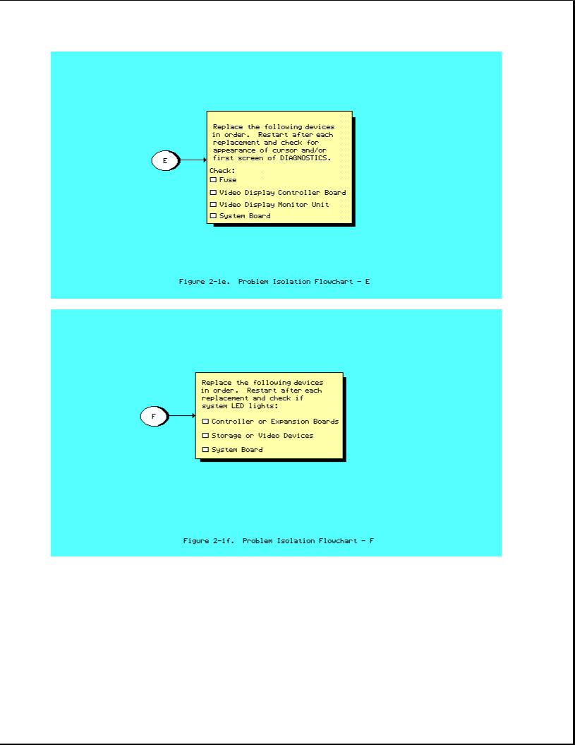
Chapter 2.4 Problem Isolation Flowchart
The problem isolation flowchart provides a quick reference for identifying and correcting possible problems that may occur during POST. The flowchart gives troubleshooting procedures for identifying malfunctions and replacing major assemblies in the computer and directs you to Chapter 4, "Diagnostic Procedures," and to Chapter 5, "Error Messages and Codes," for more detailed troubleshooting information.


Chapter 3. Setup
Please consult the SUPPORT SOFTWARE MAINTENANCE AND SERVICE GUIDE for current information on SETUP.

Chapter 4. Diagnostic Procedures
Please consult the SUPPORT SOFTWARE MAINTENANCE AND SERVICE GUIDE for current information on DIAGNOSTICS.

Chapter 5. Error Messages and Codes
Chapter 5.1 Introduction
This section provides Power On Self Test error messages, DIAGNOSTIC error codes, and memory error codes.
The messages and codes are given in tables that list the message or error code, a description of the error, and the probable failure or required action to resolve the error condition.
Chapter 5.2 Power On Self Test Error Messages
This section is divided into two tables. The first table contains Power On Self Test error messages for the COMPAQ PORTABLE 286 Personal Computer. The second table contains Power On Self Test error messages for the COMPAQ Portable and COMPAQ PLUS Personal Computers.
An error message results if a problem is encountered during the Power On Self Test program. This program runs automatically when the system is turned on.
The tables list the messages, the audible (beep) message, and the probable failure.
Table 5-1. Power On Self Test Error Messages for the COMPAQ PORTABLE 286 Personal Computer
==============================================================================
Message Beeps Probable Failure
------------------------------------------------------------------------------
101 - I/O ROM Error |
1 |
Long, |
Option ROM |
|
1 |
Short |
|
------------------------------------------------------------------------------
101 - ROM Error |
1 |
Long, |
System ROM |
|
1 |
Short |
|
------------------------------------------------------------------------------
102 - System Board Failure None System Board
------------------------------------------------------------------------------
162 - System Options Error 2 Short SETUP Utility Incorrect
------------------------------------------------------------------------------
163 - Time & Date Not Set 2 Short Invalid time
------------------------------------------------------------------------------
164 - Memory Size Error 2 Short SETUP Utility Incorrect Discrepancy
------------------------------------------------------------------------------
XX000B YYZZ - 201 Memory |
None |
RAM Failure * |
Error |
|
|
------------------------------------------------------------------------------
301 - Keyboard Error None Keyboard
------------------------------------------------------------------------------
302 - System Unit Security |
2 Short |
System Lock |
Lock is Locked, Unlock |
|
|
System Unit Security Lock
------------------------------------------------------------------------------
303 - |
Keyboard Controller |
None |
Keyboard |
Error |
|
|
|
------------------------------------------------------------------------------
304 - Keyboard or System |
None |
Keyboard |
Unit Error |
|
|
------------------------------------------------------------------------------
*See Section 5.4, "Memory Error Codes," for the location of the defective memory chip.
------------------------------------------------------------------------------
Message Beeps Probable Failure
------------------------------------------------------------------------------
402 - Monochrome Display |
1 |
Long, |
Monochrome Display Controller Board |
Controller Failure |
2 |
Short |
|
------------------------------------------------------------------------------
501 - Display Controller |
1 |
Long, |
Video |
Display or Video Controller |
Failure |
2 |
Short |
Board |
|
------------------------------------------------------------------------------
601 - Diskette Controller None Diskette Controller Board Error
------------------------------------------------------------------------------
1780 - Disk 0 Failure None Fixed Disk Drive
------------------------------------------------------------------------------
1782 - Disk Controller None Fixed Disk Drive Failure
------------------------------------------------------------------------------
1790 - Disk 0 Error None Fixed Disk Drive Recalibration
------------------------------------------------------------------------------
Parity |
Check 2 XX000B |
None |
Expansion RAM |
(Main Memory on COMPAQ |
YYZZ * |
|
|
PORTABLE 286) |
|
------------------------------------------------------------------------------
Audible |
1 Short |
Power |
On successful: COMMON (6 MHz) |
|
|
speed |
|
------------------------------------------------------------------------------
Audible |
2 Short |
Power |
On successful: FAST (8 MHz) |
|
|
speed |
|
------------------------------------------------------------------------------
RESUME = "F1" KEY None Any failure
------------------------------------------------------------------------------
*See Section 5.4, "Memory Error Codes," for the location of the defective memory chip.
==============================================================================
Table 5-2. Power On Self Test Error Messages for the COMPAQ Portable and COMPAQ PLUS Personal Computers
==============================================================================
Message Beeps Probable Failure
------------------------------------------------------------------------------
Audible 1 Beep Power On successful
------------------------------------------------------------------------------
1XX |
1 |
Long, |
System ROM or System Board |
|
1 |
Short |
|
------------------------------------------------------------------------------
XXYY 20X None Failure
------------------------------------------------------------------------------
3XX or dd 3XX None Keyboard assembly or "stuck" key
------------------------------------------------------------------------------
4XX |
None |
Diskette/Printer Board |
||
|
1 |
Long, |
Video |
Display Unit or Video Controller |
|
2 |
Short |
Board |
|
------------------------------------------------------------------------------
5XX 1 Long, Video Display Unit (VDU) or Video

2 Short Controller Board
------------------------------------------------------------------------------
6XX None Disk Drive Assembly
------------------------------------------------------------------------------
170X None Fixed Disk Drive Assembly
==============================================================================
Chapter 5.3 Diagnostic Error Codes
DIAGNOSTIC error codes occur if the system recognizes a problem while running the COMPAQ DIAGNOSTICS Program. These error codes help identify possible defective subassemblies.
Table 5.3 lists all possible error codes, a description of the error condition, and the action required to resolve the error condition.
In each case, the required action lists prioritized steps necessary to correct the problem. After each step is completed, run DIAGNOSTICS to verify whether the error condition has been corrected. If the error code reappears, perform the next step, then run the DIAGNOSTICS Program. Follow this procedure until the DIAGNOSTICS Program no longer detects an error condition.
For assistance in the removal and replacement of a particular subassembly, see Chapter 7, "Removal and Replacement Procedures."
Table 5-3. DIAGNOSTIC Error Codes
==============================================================================
Error |
Error |
Required |
Code |
Description |
Action |
------------------------------------------------------------------------------
Processor 1yy - xx
------------------------------------------------------------------------------
101 - 01 286 CPU test failed Replace the system board.
------------------------------------------------------------------------------
102 |
- 01 |
287 |
Coprocessor |
initial |
The following steps apply to error |
||
|
|
status word incorrect |
codes 102 - 01 through 102 - 15: |
||||
102 |
- 02 |
287 |
Coprocessor |
initial |
1. |
Replace the 287 Coprocessor. |
|
|
|
control |
word incorrect |
2. |
Replace the system board. |
||
102 |
- 03 |
287 |
Coprocessor |
tag word |
|
|
|
|
|
not all |
ones |
|
|
|
|
102 |
- 04 |
287 |
Coprocessor |
tag word |
|
|
|
|
|
not all |
zeros |
|
|
|
|
102 |
- 05 |
287 |
Coprocessor |
exchange |
|
|
|
|
|
command |
failed |
|
|
|
|
102 |
- 06 |
287 |
Coprocessor |
masked |
|
|
|
|
|
exception incorrectly |
|
|
|||
|
|
handled |
|
|
|
|
|
102 |
- 07 |
287 |
Coprocessor |
unmasked |
|
|
|
|
|
exception codes |
incorrectly |
|
|
||
|
|
handled |
|
|
|
|
|

102 - 08 287 Coprocessor wrong mask bit set in status register
102 - 15 287 socket is unoccupied, or 287 is inoperative
------------------------------------------------------------------------------
Error |
Error |
Required |
Code |
Description |
Action |
------------------------------------------------------------------------------
103 |
- 01 |
8237 |
DMA page registers |
Replace the system board for error |
|||
|
|
test |
|
|
|
|
codes 103 - 01 through 113 - 01. |
103 |
- 02 |
8237 |
DMA byte controller |
|
|||
|
|
test failed |
|
|
|
|
|
103 |
- 03 |
8237 |
DMA word controller |
|
|||
|
|
test failed |
|
|
|
|
|
104 |
- 01 |
8259 |
interrupt |
controller |
|
||
|
|
master test failed |
|
|
|||
104 |
- 02 |
8259 |
interrupt |
controller |
|
||
|
|
slave test |
failed |
|
|
||
104 |
- 03 |
8259 |
software RTC |
is |
|
||
|
|
inoperative |
|
|
|
|
|
105 |
- 01 |
Port bit 6 |
not |
at |
zero |
|
|
105 |
- 02 |
Port bit 5 |
not |
at |
zero |
|
|
105 |
- 03 |
Port bit 3 |
not |
at |
zero |
|
|
105 |
- 04 |
Port bit 1 |
not |
at |
zero |
|
|
105 |
- 05 |
Port bit 0 |
not |
at |
zero |
|
|
105 |
- 06 |
Port bit 5 |
not |
at |
one |
|
|
105 |
- 07 |
Port bit 3 |
not |
at |
one |
|
|
105 |
- 08 |
Port bit 1 |
not |
at |
one |
|
|
105 |
- 09 |
Port bit 0 |
not |
at |
one |
|
|
------------------------------------------------------------------------------
Error |
Error |
Required |
Code |
Description |
Action |
------------------------------------------------------------------------------
Processor 1yy - xx
------------------------------------------------------------------------------
106 |
- |
01 |
8042 |
keyboard |
controller |
Replace the |
system board for |
error |
|
|
|
self test failed |
codes 103 - |
01 through 113 - |
01. |
||
107 |
- |
01 |
CMOS |
RAM test |
failed |
|
|
|
108 - 02 CMOS interrupt test failed

109 |
- 01 |
CMOS clock |
load data test |
|
|
failed |
|
109 |
- 02 |
CMOS clock |
rollover test |
|
|
failed |
|
110 |
- 01 |
8254 load data test failed |
|
110 |
- 02 |
8254 dynamic test failed |
|
111 |
- 01 |
Refresh detect test failed |
|
112 |
- 01 |
Speed test |
slow mode out of |
|
|
range |
|
112 |
- 02 |
Speed test |
mixed mode out |
|
|
of range |
|
112 |
- 03 |
Speed test |
fast mode out of |
|
|
range |
|
112 |
- 04 |
Speed test |
unable to enter |
|
|
slow mode |
|
112 |
- 05 |
Speed test |
unable to enter |
|
|
mixed mode |
|
112 |
- 06 |
Speed test |
unable to enter |
|
|
fast mode |
|
112 |
- 07 |
Speed test |
system error |
113 |
- 01 |
Protected mode test failed |
|
------------------------------------------------------------------------------
114 - 01 |
Speaker test failed |
1. |
Replace |
the |
speaker. |
|
|
2. |
Replace |
the |
system board. |
------------------------------------------------------------------------------
Error |
Error |
Required |
Code |
Description |
Action |
------------------------------------------------------------------------------
Memory * 2yy - xx
------------------------------------------------------------------------------
201 |
- 01 |
Memory machine ID |
test |
The |
following steps apply to error |
|
|
|
|
codes 201 - 01 through 202 - 01: |
|
201 |
- 02 |
Memory machine type test |
(Error during saving test program |
||
|
|
failed |
|
memory): |
|
201 |
- 03 |
Memory machine ID |
& type |
1. |
Replace VDU controller board. |
|
|
tests failed |
|
2. |
Replace the system ROM. |
|
|
|
|
3. |
Replace the system board. |
202 |
- 01 |
Memory system ROM |
checksum |
|
|
failed
------------------------------------------------------------------------------
203 |
- |
01 |
Memory write/read test |
The |
following steps apply |
to |
error |
||
|
|
|
failed |
codes 203 - 01 through 205 - 03: |
|||||
203 |
- |
02 |
Error during saving program |
1. |
Replace |
the |
defective |
memory |
|
|
|
|
memory in write/read test |
|
chip if |
an error code |
is |
|
|
|
|
|
|
|
accompanied |
by an XX000B |
YYZZ |
||

203 |
- 03 |
Error during restore of |
code. |
|
|
program in write/read test |
2. Replace the system board. |
204 |
- 01 |
Memory address test failed |
|
204 |
- 02 |
Error during saving program |
|
|
|
memory in address test |
|
204 |
- 03 |
Error during restore of |
|
|
|
program memory address test |
|
205 |
- 01 |
Walking I/O test failed |
|
205 |
- 02 |
Error during saving program |
|
|
|
memory in walking I/O test |
|
205 |
- 03 |
Error during restore of |
|
|
|
program memory in walking |
|
I/O test
------------------------------------------------------------------------------
* See Section 5.4, "Memory Error Codes."
------------------------------------------------------------------------------
Error |
Error |
Required |
Code |
Description |
Action |
------------------------------------------------------------------------------
Keyboard 3yy - xx
------------------------------------------------------------------------------
301 |
- 01 |
Keyboard short test, 8042 |
The following steps apply to error |
||
|
|
self test failed |
codes 301 - 01 through 304 - 01: |
||
301 |
- 02 |
Keyboard short test, |
1. |
Replace the keyboard. |
|
|
|
interface test failed |
2. |
Replace the system board. |
|
301 |
- 03 |
Keyboard short test, echo |
|
|
|
|
|
test failed |
|
|
|
301 |
- 04 |
Keyboard short test, |
|
|
|
|
|
keyboard reset failed |
|
|
|
302 |
- 01 |
Keyboard long test failed |
|
|
|
303 |
- 01 |
Keyboard LED |
test, 8042 |
|
|
|
|
self test failed |
|
|
|
303 |
- 02 |
Keyboard LED |
test, reset |
|
|
|
|
test failed |
|
|
|
303 |
- 03 |
Keyboard LED |
test, reset |
|
|
|
|
test failed |
|
|
|
303 |
- 04 |
Keyboard LED |
test, LED |
|
|
|
|
command test |
failed |
|
|
303 |
- 05 |
Keyboard LED |
test, LED |
|
|
|
|
command test |
failed |
|
|
303 |
- 06 |
Keyboard LED |
test, LED |
|
|
|
|
command test |
failed |
|
|

303 |
- 07 |
Keyboard LED |
test, |
LED |
|
|
command test |
failed |
|
303 |
- 08 |
Keyboard LED |
test, |
command |
|
|
byte restore |
test failed |
|
303 |
- 09 |
Keyboard LED |
test, |
LEDs |
|
|
failed to light |
|
|
304 |
- 01 |
Keyboard typomatic |
test |
|
|
|
failed |
|
|
------------------------------------------------------------------------------
315 |
- |
01 |
Security |
lock is |
1. Replace the security lock. |
|
|
|
inoperative |
|
|
315 |
- |
02 |
Security |
lock sticks in |
|
locked position
------------------------------------------------------------------------------
Error |
Error |
Required |
Code |
Description |
Action |
------------------------------------------------------------------------------
Printer 4yy - xx
------------------------------------------------------------------------------
401 |
- 01 |
Printer failed or not |
The |
following steps apply to error |
|
|
connected |
codes 401 - 01 through 403 - 01: |
|
402 |
- 01 |
Printer data register |
1. |
If a printer is connected, be |
|
|
failed |
|
sure it is turned ON and in |
|
|
|
|
the online mode. |
402 |
- 02 |
Printer controller register |
2. |
Check switch 2 on the |
|
|
failed |
|
diskette/tape controller board |
|
|
|
|
(see Chapter 8). * |
402 |
- 03 |
Printer data and controller |
3. |
Replace the printer and/or the |
|
|
register failed |
|
printer controller cable. |
|
|
|
4. |
Replace the diskette/tape |
402 |
- 04 |
Printer loopback failed |
|
controller board. * |
|
|
|
5. |
Replace the system board. |
402 |
- 05 |
Printer loopback and data |
|
|
|
|
register failed |
* 286 based COMPAQ Personal |
|
|
|
|
Computers only |
|
402 |
- 06 |
Printer loopback and |
|
|
|
|
controller register failed |
|
|
402 |
- 07 |
Printer loopback, data, |
|
|
|
|
and controller register |
|
|
|
|
failed |
|
|
402 |
- 08 |
Printer interrupt test |
|
|
|
|
failed |
|
|
402 |
- 09 |
Printer interrupt and data |
|
|
failed
------------------------------------------------------------------------------
Error |
Error |
Required |
Code |
Description |
Action |
------------------------------------------------------------------------------
402 - 10 |
Printer interrupt and |
The following steps apply to |
error |
|
controller register failed |
codes 401 - 01 through 403 - |
01: |

402 |
- 11 |
Printer interrupt data, and |
1. |
If a printer is connected, be |
|
|
|
controller register failed |
|
sure it |
is turned ON and in |
|
|
|
|
the online mode. |
|
402 |
- 12 |
Printer interrupt and |
2. |
Check switch 2 on the |
|
|
|
loopback failed |
|
diskette/tape controller board |
|
|
|
|
|
(see Chapter 8). * |
|
402 |
- 13 |
Printer interrupt, loopback, |
3. |
Replace |
the printer and/or the |
|
|
and data register failed |
|
printer |
controller cable. |
|
|
|
4. |
Replace |
the diskette/tape |
402 |
- 14 |
Printer interrupt, loopback, |
|
controller board. * |
|
|
|
and controller register |
5. |
Replace |
the system board. |
|
|
failed |
|
|
|
|
|
|
* 286 based |
COMPAQ Personal |
|
402 |
- 15 |
Printer interrupt, |
|
Computers |
only |
|
|
loopback, data, and |
|
|
|
|
|
controller register failed |
|
|
|
402 |
- 16 |
Printer unexpected |
|
|
|
|
|
interrupt received |
|
|
|
403 |
- 01 |
Printer pattern test failed |
|
|
|
------------------------------------------------------------------------------
Error |
Error |
Required |
Code |
Description |
Action |
------------------------------------------------------------------------------
Video Display Unit (VDU) 5yy - xx
------------------------------------------------------------------------------
501 |
- 01 |
VDU controller test failed |
The following steps apply to error |
|
|
|
|
codes 501 - 01 through 512 - 01: |
|
502 |
- 01 |
VDU memory test failed |
|
|
|
|
|
1. Replace the VDU controller |
|
503 |
- 01 |
VDU attribute test failed |
|
board. |
|
|
|
2. Replace the VDU signal cable. |
|
504 |
- 01 |
VDU character set test |
3. |
Replace VDU subassembly. |
|
|
failed |
4. |
Replace the system board. |
505 |
- 01 |
VDU 9 x 14 character cell |
|
|
|
|
test |
|
|
506 |
- 01 |
VDU 80 x 25 mode 8 x 8 |
|
|
|
|
character cell test |
|
|
|
|
failed |
|
|
507 |
- 01 |
VDU 40 x 25 mode test |
|
|
|
|
failed |
|
|
508 |
- 01 |
VDU 320 x 200 mode color |
|
|
|
|
set 0 test failed |
|
|
509 |
- 01 |
VDU 320 x 200 mode color |
|
|
|
|
set 1 test failed |
|
|
510 |
- 01 |
VDU 640 x 200 mode test |
|
|
|
|
failed |
|
|
511 |
- 01 |
VDU screen memory page test |
|
|
|
|
failed |
|
|
512 - 01 VDU gray scale test failed

------------------------------------------------------------------------------
Error |
Error |
Required |
Code |
Description |
Action |
------------------------------------------------------------------------------
516 |
- 01 |
Lightpen |
text mode test |
The |
following steps apply to error |
|
|
failed - |
no response |
codes 516 - 01 through 516 - 04: |
|
516 |
- 0 |
Lightpen |
text mode test |
1. |
Replace the lightpen. |
|
|
failed - |
invalid response |
2. |
Replace the VDU controller |
|
|
|
|
|
board. |
516 |
- 03 |
Lightpen |
medium resolution |
|
|
|
|
mode test failed - no |
|
|
|
|
|
response |
|
|
|
516 |
- 04 |
Lightpen |
medium resolution |
|
|
|
|
mode test - invalid response |
|
|
|
------------------------------------------------------------------------------
Diskette Drive 6yy - xx
------------------------------------------------------------------------------
600 |
- xx |
Diskette drive ID |
The |
following steps apply to all |
|
|
|
|
6yy |
- xx related error codes. |
|
601 |
- xx |
Diskette drive format |
|
|
|
|
|
|
1. |
Check shunt jumper J2 setting |
|
602 |
- xx |
Diskette drive read |
|
on the diskette/tape |
|
|
|
|
|
controller board (see |
|
603 |
- xx |
Diskette drive write/read/ |
|
Chapter |
8). * |
|
|
compare |
2. |
Replace |
the diskette/tape |
|
|
|
|
controller board. * |
|
604 |
- xx |
Diskette drive random seek |
3. |
Replace |
the diskette drive |
|
|
drive |
|
power and signal cables. |
|
|
|
|
4. |
Replace |
the diskette drive |
605 |
- xx |
Diskette drive ID media |
|
assembly. |
|
|
|
test |
5. |
Replace |
the system board. |
606 |
- xx |
Diskette drive speed test |
* 286 based |
COMPAQ Personal |
|
|
|
|
Computers |
only |
|
607 |
- xx |
Diskette drive wrap test |
|
|
|
608 |
- xx |
Diskette drive write |
|
|
|
|
|
protect test |
|
|
|
609 |
- xx |
Diskette drive reset |
|
|
|
controller test
------------------------------------------------------------------------------
Error |
Error |
Required |
Code |
Description |
Action |
------------------------------------------------------------------------------
Diskette Drive 6yy - xx
------------------------------------------------------------------------------
610 |
- xx |
Diskette drive change |
line |
The |
following steps apply |
to all |
|
|
test |
|
6yy |
- xx related error codes. |
|
610 |
- 01 |
Exceeded maximum soft |
error |
1. |
Check shunt jumper J2 |
setting |
|
|
limit |
|
|
on the diskette/tape |
|
|
|
|
|
|
controller board (see |
|
610 |
- 02 |
Exceeded maximum hard |
error |
|
Chapter 8). * |
|
|
|
limit |
|
2. |
Replace the diskette/tape |
|
|
|
|
|
|
controller board. * |
|

610 |
- 03 |
Previously |
exceeded max |
3. |
Replace |
the diskette drive |
|
|
soft error |
limit |
|
power and signal cables. |
|
|
|
|
|
4. |
Replace |
the diskette drive |
610 |
- 04 |
Previously |
exceeded max |
|
assembly. |
|
|
|
hard error |
limit |
5. |
Replace |
the system board. |
610 |
- 05 |
Failed to reset controller |
* 286 based |
COMPAQ Personal |
||
|
|
|
|
|
Computers |
only |
610 |
- 06 |
Fatal error while reading |
|
|
|
|
610 |
- 07 |
Fatal error while writing |
|
|
|
|
610 |
- 08 |
Failed compare of write/ |
|
|
|
|
read/compare
------------------------------------------------------------------------------
Error |
Error |
Required |
Code |
Description |
Action |
------------------------------------------------------------------------------
Diskette Drive 6yy - xx
------------------------------------------------------------------------------
6xx - 09 |
Failed to format a track |
The |
following steps apply to all |
|
|
|
|
6yy |
- xx related error codes. |
610 |
- 10 |
Failed sector wrap test |
|
|
|
|
|
1. |
Check shunt jumper J2 setting |
610 |
- 20 |
Failed to get drive type |
|
on the diskette/tape |
|
|
|
|
controller board (see |
610 |
- 21 ** Failed to get change line |
|
Chapter 8). * |
|
|
|
status |
2. |
Replace the diskette/tape |
|
|
|
|
controller board. * |
610 |
- 22 |
Failed to clear change |
3. |
Replace the diskette drive |
|
|
|
|
power and signal cables. |
610 |
- 23 |
Failed to set drive type in |
4. |
Replace the diskette drive |
|
|
ID media |
|
assembly. |
|
|
|
5. |
Replace the system board. |
610 |
- 24 |
Failed to read media |
|
|
|
|
|
* 286 based COMPAQ Personal |
|
610 |
- 25 |
Failed to verify media |
Computers only |
|
610 |
- 26 |
Failed to read media in |
** The following applies to |
|
|
|
speed test |
|
286 based computers: |
610 |
- 27 |
Failed speed limits |
For a 1.2 megabyte diskette |
|
|
|
|
drive, replace the diskette |
|
610 |
- 28 |
Failed write protect test |
drive. For a 360 Kbyte |
|
|
|
|
diskette drive, a drive |
|
610 |
- 29 |
Failed to read media in |
modification has not been |
|
|
|
file write test |
performed. See Service |
|
|
|
|
Bulletin 25. |
|
610 |
- 40 |
Cylinder 0 Error |
|
|
------------------------------------------------------------------------------
Error |
Error |
Required |
Code |
Description |
Action |
------------------------------------------------------------------------------
Serial 11yy - xx
------------------------------------------------------------------------------
1101 - 01 |
Serial Port Test, UART |
The following steps apply to all |
|
DLAB bit failure |
11yy - xx related error codes: |

1101 |
- 02 |
Serial Port Test, Line |
1. |
Check diskette/tape controller |
|
|
input or UART fault |
|
board for proper shunt jumper |
|
|
|
|
settings (see Chapter 8). * |
1101 |
- 03 |
Serial Port Test, Address |
2. |
Replace the diskette/tape |
|
|
line fault |
|
controller board. |
|
|
|
3. |
Replace the system board. |
1101 - 04 Serial Port Test, Data line fault
*286 based COMPAQ Personal Computers only
1101 |
- 05 |
Serial Port Test, |
UART |
|
|
control signal |
|
1101 |
- 06 |
Serial Port Test, |
ART THRE |
|
|
bit failure |
|
1101 |
- 07 |
Serial Port Test, |
UART DATA |
|
|
READY bit failure |
|
1101 |
- 08 |
Serial Port Test, |
UART |
|
|
TX/RX buffer failure |
|
1101 |
- 09 |
Serial Port Test, |
INTERRUPT |
|
|
circuit failure |
|
1101 |
- 10 |
Serial Port Test, |
COM 1 set |
|
|
to interrupt 3 |
|
------------------------------------------------------------------------------
Error |
Error |
Required |
Code |
Description |
Action |
------------------------------------------------------------------------------
Serial 11yy - xx
------------------------------------------------------------------------------
1101 |
- 11 |
Serial |
Port Test, COM 2 |
The |
following steps apply to all |
|
|
set to |
interrupt 4 |
11yy - xx related error codes: |
|
1101 |
- 12 |
Serial |
Port Test, |
1. |
Check diskette/tape controller |
|
|
DRIVER/RECEIVER control |
|
board for proper shunt jumper |
|
|
|
signal |
failure |
|
settings (see Chapter 8). * |
|
|
|
|
2. |
Replace the diskette/tape |
1101 |
- 13 |
Serial |
Port Test, UART |
|
controller board. |
|
|
control signal interrupt |
3. |
Replace the system board. |
|
|
|
failure |
|
|
|
|
|
|
|
* 286 based COMPAQ Personal |
|
1101 |
- 14 |
Serial |
Port Test, |
Computers only |
|
|
|
DRIVER/RECEIVER data failure |
|
|
|
1109 |
- 01 |
Serial |
Clock Test, register |
|
|
|
|
initialization failure |
|
|
|
1109 |
- 02 |
Serial |
Clock Test, register |
|
|
|
|
rollover failure |
|
|
|
1109 |
- 03 |
Serial |
Clock Test, clock |
|
|
|
|
reset failure |
|
|
|
1109 |
- 04 |
Serial |
Clock Test, input |
|
|
|
|
line or clock failure |
|
|
|
1109 - 05 Serial Clock Test, address
Loading...