


 Loading...
Hardware Reference Guide
Compaq Deskpro EN Series of Personal Computers
Slim Desktop Models

Hardware Reference Guide
Compaq Deskpro EN Series
of Personal Computers
Slim Desktop Models

Notice
Compaq Computer Corporation shall not be liable for technical or editorial errors or omissions contained herein. The information in this guide is subject to change without notice.
© 2000 Compaq Computer Corporation. Except for use in connection with the accompanying Compaq product, no part of this guide may be photocopied or reproduced in any form without prior written consent from Compaq Computer Corporation.
COMPAQ, the Compaq logo, and Deskpro Registered in U.S. Patent and Trademark Office.
Microsoft, Windows, Windows NT, and other names of Microsoft products referenced herein are trademarks or registered trademarks of Microsoft Corporation.
Intel and Pentium are registered trademarks of Intel Corporation. Celeron and MMX are trademarks of Intel Corporation.
All other product names mentioned herein may be trademarks or registered trademarks of their respective companies. Printed in U.S.A.
The following words and symbols mark special messages throughout this guide:
WARNING: Text set off in this manner indicates that failure to follow directions could result in bodily harm or loss of life.
CAUTION: Text set off in this manner indicates that failure to follow directions could result in damage to equipment or loss of information.
Hardware Reference Guide
Compaq Deskpro EN Series of Personal Computers
Slim Desktop Models
First Edition (October 2000)
Part Number 178171-002
Compaq Computer Corporation

CONTENTS
chapter 1
Installation Guidelines
Installation Sequence ............................................................................................................... |
1-1 |
When to Reconfigure the Computer......................................................................................... |
1-3 |
chapter 2
Hardware Upgrades
Serviceability Features............................................................................................................. |
2-1 |
Removing the Access Panel ............................................................................................... |
2-1 |
Rotating the Drive Cage..................................................................................................... |
2-3 |
Internal Components (Intel 815e Chipset) ............................................................................... |
2-4 |
Installing Additional Memory.................................................................................................. |
2-5 |
DIMMs............................................................................................................................... |
2-5 |
Memory Module Installation.............................................................................................. |
2-5 |
Installing an Expansion Card ................................................................................................... |
2-7 |
Removing an Expansion Slot Cover................................................................................... |
2-7 |
Removing or Installing a PCI Card .................................................................................... |
2-8 |
Installing Additional Drives................................................................................................... |
2-10 |
Removing a Blank Drive Bezel........................................................................................ |
2-10 |
Installing a Diskette, CD-ROM, DVD-ROM, or Tape Drive........................................... |
2-11 |
Installing a Hard Drive..................................................................................................... |
2-13 |
Removing a CD-ROM Drive from the Drive Cage ............................................................... |
2-16 |
Removing a Diskette Drive from the Drive Cage .................................................................. |
2-17 |
Removing a Hard Drive from the Drive Cage ....................................................................... |
2-18 |
Smart Cover Lock.................................................................................................................. |
2-20 |
Using the Smart Cover FailSafe Key ............................................................................... |
2-20 |
Hardware Reference Guide iii

appendix a |
|
Specifications .................................................................................................................................... |
A-1 |
appendix b |
|
Hard Drive Installation Guidelines |
|
Using the Cable-Select Feature with Ultra ATA Devices........................................................ |
B-1 |
Installing SCSI Devices ........................................................................................................... |
B-2 |
Guidelines for Installing Optional SCSI Devices............................................................... |
B-2 |
Cabling for Optional SCSI Devices ................................................................................... |
B-4 |
Using SCSISelect with SCSI Devices ................................................................................ |
B-5 |
appendix c |
|
Battery Replacement.......................................................................................................................... |
C-1 |
appendix d |
|
Security Lock Provisions |
|
Installing a Cable Lock ........................................................................................................... |
D-1 |
appendix e |
|
Electrostatic Discharge |
|
Preventing Electrostatic Damage ............................................................................................. |
E-1 |
Grounding Methods ................................................................................................................. |
E-2 |
appendix f |
|
Routine Computer Care and Shipping Preparation |
|
Routine Computer Care ........................................................................................................... |
F-1 |
CD-ROM Drive Precautions.................................................................................................... |
F-2 |
Operation............................................................................................................................ |
F-2 |
Cleaning ............................................................................................................................. |
F-2 |
Safety ................................................................................................................................. |
F-2 |
Shipping Preparation................................................................................................................ |
F-3 |
Index ..................................................................................................................................................... |
I-1 |
iv Contents

chapter 1
INSTALLATION GUIDELINES
This guide explains how to remove the computer cover or access panel and install the following optional equipment upgrades:
Additional system memory
Expansion card
Optional drive
Security lock
Replacement battery
This chapter includes information about the general installation sequence for Deskpro personal computers, and about when to reconfigure the computer to ensure that it recognizes the newly installed equipment.
Installation Sequence
It is very important that you follow this sequence of steps to ensure the proper installation of any optional equipment.
1.If your computer includes the Smart Cover Lock feature and you have set the lock, use Computer Setup to unlock the lock and disable the Smart Cover Sensor.
For more information about Computer Setup, refer to the Computer Setup guide.
Hardware Reference Guide 1-1

2.If the computer is already on, turn it off and disconnect the power cord from the wall outlet.
!WARNING: To reduce the risk of personal injury from electrical shock and/or hot surfaces, be sure to disconnect the power cord from the wall outlet, and allow the internal system components to cool before touching.
!WARNING: To reduce the risk of electrical shock, fire, or damage to the equipment, do not plug telecommunications/telephone connectors into the network interface controller (NIC) receptacles.
CAUTION: Static electricity can damage the electronic components of the computer or optional equipment. Before beginning these procedures, ensure that you are discharged of static electricity by briefly touching a grounded metal object. Refer to Appendix E, “Electrostatic Discharge,” for more information.
3.Open the computer by removing its outside cover. Refer to the procedures for removing the computer cover or access panel.
4.Install any optional equipment. Refer to the applicable sections of this guide or to the documentation provided with the optional equipment for instructions.
5.Replace the computer cover.
6.Turn on the monitor, computer, and any devices you want to test.
7.Reconfigure the computer, if necessary. Refer to the Computer Setup guide for instructions about using Computer Setup.
If you normally lock the Smart Cover Lock, use Computer Setup to relock the lock and enable the cover removal sensor.
1-2 Installation Guidelines

When to Reconfigure the Computer
System configuration is the process of specifying the devices and programs that make up a computer system. When you add or remove optional equipment, the computer must be reconfigured to recognize these changes.
Windows 95 and later operating systems automatically recognize all Plug and Play devices installed. However, if the device is not a Plug and Play device or is not automatically detected after installation, follow these instructions:
In Windows 95 and later operating systems, select the Add New Hardware icon in the Control Panel and follow the instructions on the screen.
To reconfigure the computer in Windows NT version 4.0, use the software utility provided with the newly installed hardware.
Hardware Reference Guide 1-3

chapter 2
HARDWARE UPGRADES
Serviceability Features
Your computer includes features that make it easier to upgrade and service.
Removing the Access Panel
The quick release cover latches, located near the rear on each side of the unit, allow easy removal of the access panel without the use of tools or thumbscrews.
!WARNING: Before removing the computer cover, ensure that the computer is turned off and that the power cord is disconnected from the electrical outlet.
If you have not already done so, you will need to loosen the silver shipping thumbscrew from the center of the rear panel before removing the cover.
1.If you have locked the Smart Cover Lock, use Computer Setup to unlock the lock and disable the Smart Cover Sensor.
2.Shut down the operating system properly, then turn off the computer and any external devices.
Hardware Reference Guide 2-1
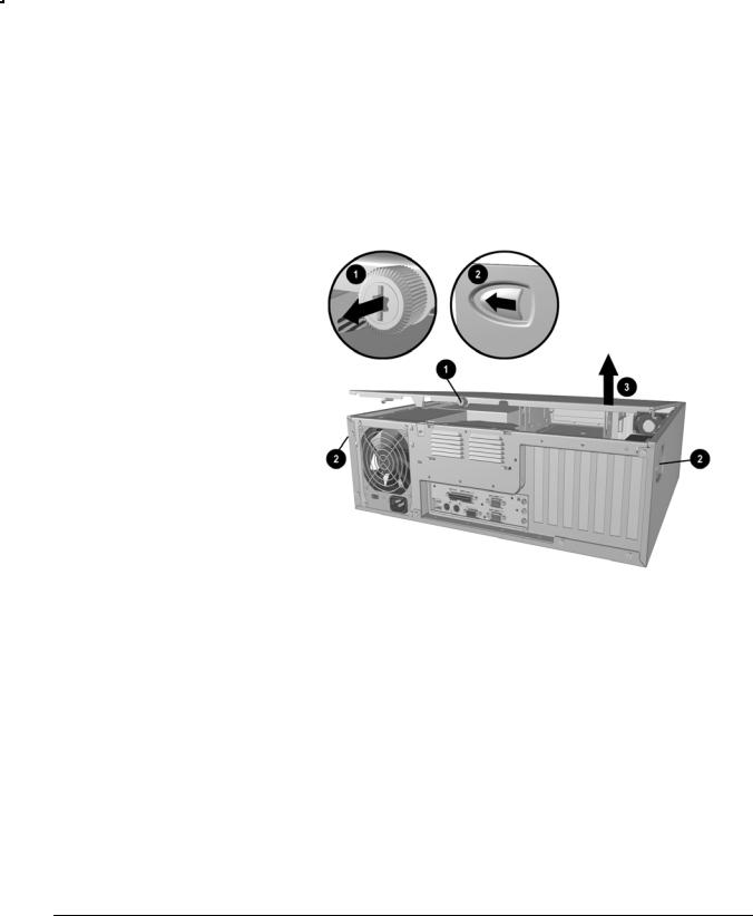
3.Disconnect the power cord from the power outlet.
4.Loosen the retaining screw located on the back of the unit .
5.Slide the cover latches on the sides near the back of the computer .
6.Lift up the back of the access panel and pull it toward the back of the unit about 1 inch (2.5 cm) so the tabs on the front of the access panel clear the case . Lift the access panel up and off the unit.
Removing the Access Panel
The configuration label located inside the computer cover provides additional information.
Another label located inside the computer chassis provides information about diagnosing computer conditions using the power and hard drive LEDs.
2-2 Hardware Upgrades
Rotating the Drive Cage
The rotating drive cage allows access to all drive bays for easy installation of additional drives, requiring no drive rails or brackets. With the drive cage rotated out from the chassis, you can easily connect the drive power and signal cables.
When installing optional drives, you must install guide screws to ensure the drive will line up correctly in the drive cage. Compaq has provided extra guide screws, installed in the bottom of the computer chassis, next to the power supply.
!WARNING: Before removing the access panel, ensure that the computer is turned off and that the power cord is disconnected from the electrical outlet.
1.If you have locked the Smart Cover Lock, use Computer Setup to unlock the lock and disable the Smart Cover Sensor.
2.Shut down the operating system properly, then turn off the computer and any external devices.
3.Disconnect the power cord from the power outlet.
4.Remove the access panel.
5.Grasp the back of the drive cage and rotate it to its upright position . The cage remains connected to the chassis.
Rotating the Drive Cage to an Upright Position
Hardware Reference Guide 2-3
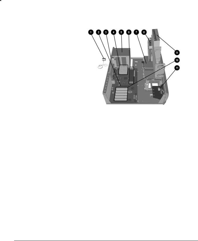
Internal Components (Intel 815e Chipset)
Internal Components in Intel 815e–Based Desktop Models
Cable lock (optional)
AGP graphics slot
Smart Cover Lock
Processor
Power supply
Dual-inline memory module (DIMM) sockets
Primary hard drive
Diskette drive
CD-ROM drive
PCI expansion slots
Speaker
2-4 Hardware Upgrades

Installing Additional Memory
The computer comes with synchronous dynamic random access memory (SDRAM) dual inline memory modules (DIMMs).
DIMMs
The memory sockets on the Intel 815e chipset–based system board can be populated with industry-standard DIMMs. These memory module slots are populated with at least one preinstalled memory module. To achieve the maximum memory support, you may be required to replace the preinstalled DIMM with a higher capacity DIMM.
For proper system operation, the DIMMs must be industry-standard 168-pin, unbuffered PC100– or PC133– compliant SDRAM DIMMs, depending on the model. The SDRAM DIMMs must support CAS Latency 2 or 3 (CL = 2 or CL = 3). They must also contain the mandatory Joint Electronic Device Engineering Council (JEDEC) Serial Presence Detect (SPD) information. DIMMs constructed with x4 SDRAM are not supported; the system will not start using unsupported DIMMs.
The Intel 815e chipset supports both PC100 and PC133 SDRAM DIMMs. PC133 DIMMs should be used for optimal performance. If both PC100 and PC133 SDRAM DIMMs are installed in a computer, the system memory will run at the lower 100Mhz speed. Some configurations of PC133 SDRAMs may run at 100Mhz, instead of 133Mhz.
Memory Module Installation
CAUTION: Your memory module sockets have gold metal contacts. When upgrading your memory, it is important to use memory modules with gold metal contacts to prevent corrosion and/or oxidation resulting from having incompatible metals in contact with each other.
CAUTION: Static electricity can damage the electronic components of the computer or optional cards. Before beginning these procedures, ensure that you are discharged of static electricity by briefly touching a grounded metal object. Refer to Appendix E, “Electrostatic Discharge,” for more information.
CAUTION: When handling a memory module, be careful not to touch any of the contacts. Doing so may damage the module.
Hardware Reference Guide 2-5

1.If you have locked the Smart Cover Lock, use Computer Setup to unlock the lock and disable the Smart Cover Sensor.
2.Shut down the operating system properly, then turn off the computer and any external devices, then disconnect the power cord from the power outlet.
3.Remove the access panel and locate the memory module sockets.
!WARNING: To reduce risk of personal injury from hot surfaces, allow the internal system components to cool before touching.
4.Open both latches of the memory module socket , and insert the memory module into the socket .
Begin by installing a module into the socket nearest the preinstalled module, and install the modules following the numerical order of the sockets.
A memory module can be installed in only one way. Match the notch on the module with the tab on the memory socket. Push the module down into the socket, ensuring that the module is fully inserted and properly seated .
Installing a DIMM
2-6 Hardware Upgrades

Installing an Expansion Card
Your computer contains expansion slots, as shown in the “Internal Components” section of this chapter. Each slot can accommodate an expansion card up to 6.88 inches (17.48 cm) in length.
Removing an Expansion Slot Cover
1.If you have locked the Smart Cover Lock, use Computer Setup to unlock the lock and disable the Smart Cover Sensor.
2.Shut down the operating system properly, turn off the computer and any external devices, then disconnect the power cord from the power outlet.
3.Remove the access panel.
4.Locate the correct vacant expansion card slot on the back of the computer.
5.Remove the screw at the top of the expansion slot cover, then remove the expansion slot cover from the slot as illustrated.
Removing a Screw and Expansion Slot Cover
Hardware Reference Guide 2-7
Loading...