


iDP-3540

iDP-3540/41 User’s Manual
CITIZEN
User’s Manual
MINI DOT MATRIX PRINTER
MODEL
iDP-3540/3541
Japan CBM Corporation
Information Systems Div.
CITIZEN 1/48

iDP-3540/41 User’s Manual
1995.09.04(10-DCL)1
Declaration of Conformity
Manufacturer's Name : : Japan CBM Corporation
Manufacturer's Address : 1-1-7, Okubo, Shinjuku-ku, Tokyo
169, Japan
Declare the Product
Product Name Dot Matrix Printer
Model Number (s) iDP-3540, 3541 Series
(iDP3540R, iDP3540P, iDP3541R, iDP3541P)
(S.NO.50901072 - )
Conform to the following Standards
LVD : EN60950 :1992+A1+A2:1993
EMC : EN55022 :1994 Class B
: EN60555-2 :1987
: EN50082-1 :1992
: IEC801-2 :1991 4KV CD, 8KV AD
: IEC801-3 :1984 3V/m, 27MHz-500MHz
: IEC801-4 :1988 0.5KV Signal Line 1KV AC mains
Supplementary Information
"The product complies with the requirements of the Low Voltage Directive 73/23/EEC,
93/68/EEC and the EMC Directive 89/336EEC, 92/31/EEC, 93/68EEC"
Place Tokyo, Japan Signature
Date
Europe Contact :
Warning
This is a Class A products. In a domestic environment this product may cause radio interference
in which case the user may be required to take adequate measures.
This declaration is applied only for 230V model.
Sept.1995
Full Name : Koji Tanabe
Position : General Manager
R & D Department
Europe Liaison Office
Kuruisweg 805, Holland Office Center Building
3-2132 NG Hoofddorp, the Netherlands
CITIZEN 2/48

iDP-3540/41 User’s Manual
IMPORTANT SAFETY INSTRUCTIONS
s Read all of these instructions and save them for later reference.
s Follow all warnings and instructions marked on the product.
s Unplug this product from the wall outlet before cleaning. Do not use liquid or aerosol cleaners.
Use a damp cloth for cleaning.
s Do not use this product near water.
s Do not place this product on an unstable cart, stand of table. The product may fall, causing serious
damage to the product.
s Slots and openings on the cabinet and the back or bottom are provided for ventilation. To ensure
reliable operation of the product and to protect it form overheating, do not block or cover these
openings. The openings should never be blocked by placing the product on a bed, sofa, rug of
other similar surface. This product should never be placed near or over a radiator or heat register.
This product should not be placed in a built-in installation unless proper ventilation is provided.
s This product should be operated from the type of power source indicated on the marking label. If
you’re not sure of the type of power available, consult your dealer or local power company.
s Do not allow anything to rest on the power cord. Do not locate this product where the cord will be
walked on.
s In an extension cord is used with this product, make sure that the total of the ampere ratings on the
products plugged into the extension cord do not exceed the extension cord ampere rating. Also,
make sure that the total of all products plugged into the wall outlet dose not exceed 15 amperes.
s Never push objects of any kind into this product through cabinet slots as they may touch
dangerous voltage points or short out parts that could result in a risk of fire or electric shock.
Never spill liquid of any kind on the product.
s Except as explained elsewhere in this manual, don’t attempt to service this product yourself.
Opening and removing those covers that are marked “Do Not Remove” may expose you to
dangerous voltage points or other risks. Refer all servicing on those compartments to service
personnel.
s Unplug this product from the wall outlet and refer servicing to qualified service personnel under
the following conditions:
A. When the power cord or plug is damaged or frayed
B. If liquid has been spilled into the product.
C. If the product has been exposed to rain or water.
D. If the product dose not operate normally when the operating instructions are followed. Adjust
only those controls that are covered by the operating instructions since improper adjustment of
other controls may result in damage and will often require extensive work by a qualified
technician to restore the product to normal operation.
E. If the product has been dropped the cabinet has been damaged.
F. If the product exhibits a distinct change in performance, indicating a need for service.
CITIZEN 3/48

iDP-3540/41 User’s Manual
CONTENTS
1. Introduction.......................................................................................................................................................6
1-1. Features......................................................................................................................................................6
1-2. Accessories ................................................................................................................................................6
2. Basic Specifications..........................................................................................................................................7
2-1. Type classifications....................................................................................................................................7
3. Specifications....................................................................................................................................................8
3-1. General Specifications...............................................................................................................................8
4. Block Diagram................................................................................................................................................10
5. External Appearance and parts Description....................................................................................................11
5-1. External appearance and parts names Model : iDP3540..........................................................................11
5-2. External appearance and parts names Model : iDP3541..........................................................................12
5-3. Parts Descriptions....................................................................................................................................13
6. Preparation ......................................................................................................................................................14
6-1. Inserting / Removing the Printer Cover...................................................................................................14
6-2. Opening and Closing the Cutter Unit (iDP3541).....................................................................................14
6-3. The Ribbon Cassette Installation .............................................................................................................15
6-4. Loading and Changing the Paper.............................................................................................................16
6-4-1. Using Paper Roll (iDP3540F, 3541).................................................................................................16
6-4-2. Using Fan-Fold Paper (iDP3540P) ...................................................................................................17
6-5. Setting / Removing the Paper Cover and Stacker....................................................................................17
6-6. Self Test Printing......................................................................................................................................18
6-7. Alarm and Paper Near-End Detection......................................................................................................18
7. Input Buffer Back-up Function .......................................................................................................................18
7-1. Input Buffer Back-up...............................................................................................................................18
7-2. Clearing the Input Buffer.........................................................................................................................18
8. Parallel Interface .............................................................................................................................................19
8-1. Specifications...........................................................................................................................................19
8-2. Connector Pin Assignment ......................................................................................................................19
8-3. Description of Input / Output Signals......................................................................................................20
8-3-1. Input / Output Signals.......................................................................................................................20
8-3-2. Electrical Characteristics..................................................................................................................21
8-3-3. Timing Chart.....................................................................................................................................22
8-3-4. Data Receiving Control....................................................................................................................22
8-3-5. Buffering...........................................................................................................................................22
9. Serial Interface................................................................................................................................................23
9-1. Specifications...........................................................................................................................................23
9-2. Connector Pin Assignment ......................................................................................................................24
9-3. Description of Input / Output Signals......................................................................................................25
9-3-1. Input / Output Signals.......................................................................................................................25
9-3-2. Data Composition.............................................................................................................................26
9-3-4. Data Receiving Control....................................................................................................................27
9-3-5. Buffering...........................................................................................................................................27
9-3-6. Electrical Characteristics..................................................................................................................28
10. External Output.............................................................................................................................................30
11. Function Selection.........................................................................................................................................31
11-1. Setting DIP Switch DS1.........................................................................................................................31
11-2. Setting DIP Switch DS2.........................................................................................................................31
CITIZEN 4/48

iDP-3540/41 User’s Manual
11-3. Slide Switch Setting (Serial interface specifications only)....................................................................32
11-4. Dip-Switch Location..............................................................................................................................32
12. Print Control Functions.................................................................................................................................33
12-1. Control Codes........................................................................................................................................33
12-2. Input Data Formats ................................................................................................................................34
12-2-1. Paper feed command for “n” lines..................................................................................................34
12-2-2. Enlarged character command..........................................................................................................34
12-2-3. Enlarged character cancel command ..............................................................................................34
12-2-4. Paper feed command ......................................................................................................................35
12-2-5. Print command................................................................................................................................35
12-2-6. Clear command...............................................................................................................................35
12-2-7. Red color print command...............................................................................................................35
12-2-8. Initial Set Command.......................................................................................................................36
12-2-9. Inverted character command...........................................................................................................36
12-2-10. Buzzer Command.........................................................................................................................36
12-2-11. Underline Command.....................................................................................................................37
12-2-12. Graphic Command (Graphic Type Only) .....................................................................................37
12-2-13. 1/9 inch Line Feed Pitch Set Command (Graphic Type)..............................................................38
12-2-14. 2/9 inch Line Feed Set Command (Graphic Type).......................................................................38
12-2-15. Page Length Set Command ..........................................................................................................39
12-2-16. From Feed Command...................................................................................................................39
12-2-17. Skip Perforation Command ..........................................................................................................39
12-2-18. Skip Perforation Cancel Command..............................................................................................40
12-2-19. Full Cut Command (iDP3541 Only).............................................................................................40
12-2-20. Partial Cut Command (iDP3541 Only).........................................................................................40
12-2-21. Drive Pulse Duration Setting Command For the First Drawer.....................................................41
12-2-22. First Drawer Drive Command......................................................................................................42
12-2-23. First Drawer Quick Drive Command............................................................................................42
12-2-24. Second Drawer Derive Command................................................................................................42
13. Initial Setting.................................................................................................................................................43
14. Maintenance..................................................................................................................................................44
15. General Cautions...........................................................................................................................................44
16. Character Code Tables ..................................................................................................................................45
17. External Dimensions.....................................................................................................................................47
17-1. Model : iDP3540....................................................................................................................................47
17-2. Model : iDP3541....................................................................................................................................48
ATTENTION : Please RESET the printer to clear the input buffer before getting started.
(Ref. to Chapter 7-2)
CITIZEN 5/48

iDP-3540/41 User’s Manual
1. Introduction
The iDP3540 is a dot impact printer which can be utilized for a wide range of applications, such as
data communications terminals, P.O.S. terminals and kitchen printers. High speed performance is
made possible by a bi-directional printing system and, since this printer is compact, lightweight and
equipped with an abundance of functions, they can be easily employed for a variety of different
tasks.
The iDP3541 has a built-in automatic cutter capable of performing a partial cut or full cut (one
connecting point remaining).
Before using the printer, please read this manual carefully to be certain you have an adequate
understanding of its operation.
1-1. Features
1) Desktop Compact Dot Impact Printer
2) High Speed Printing (Bi-directional Printing System)
3) Built-In Auto Cutter (Partial Cut / Full Cut) (iDP3541 only)
4) Black & Red 2 Color Printing or All Black or All Purple Printing
5) Paper End Detection Function
6) Input Buffer Back-up Function
7) Drawer Kick-out x 2
8) Low Power Consumption
1-2. Accessories
1) Paper Roll 1Pc. (Friction type only)
2) Ribbon Cassette 1Pc.
3) User’s Manual 1Pc.
CITIZEN 6/48
iDP-3540/41 User’s Manual
2. Basic Specifications
2-1. Type classifications
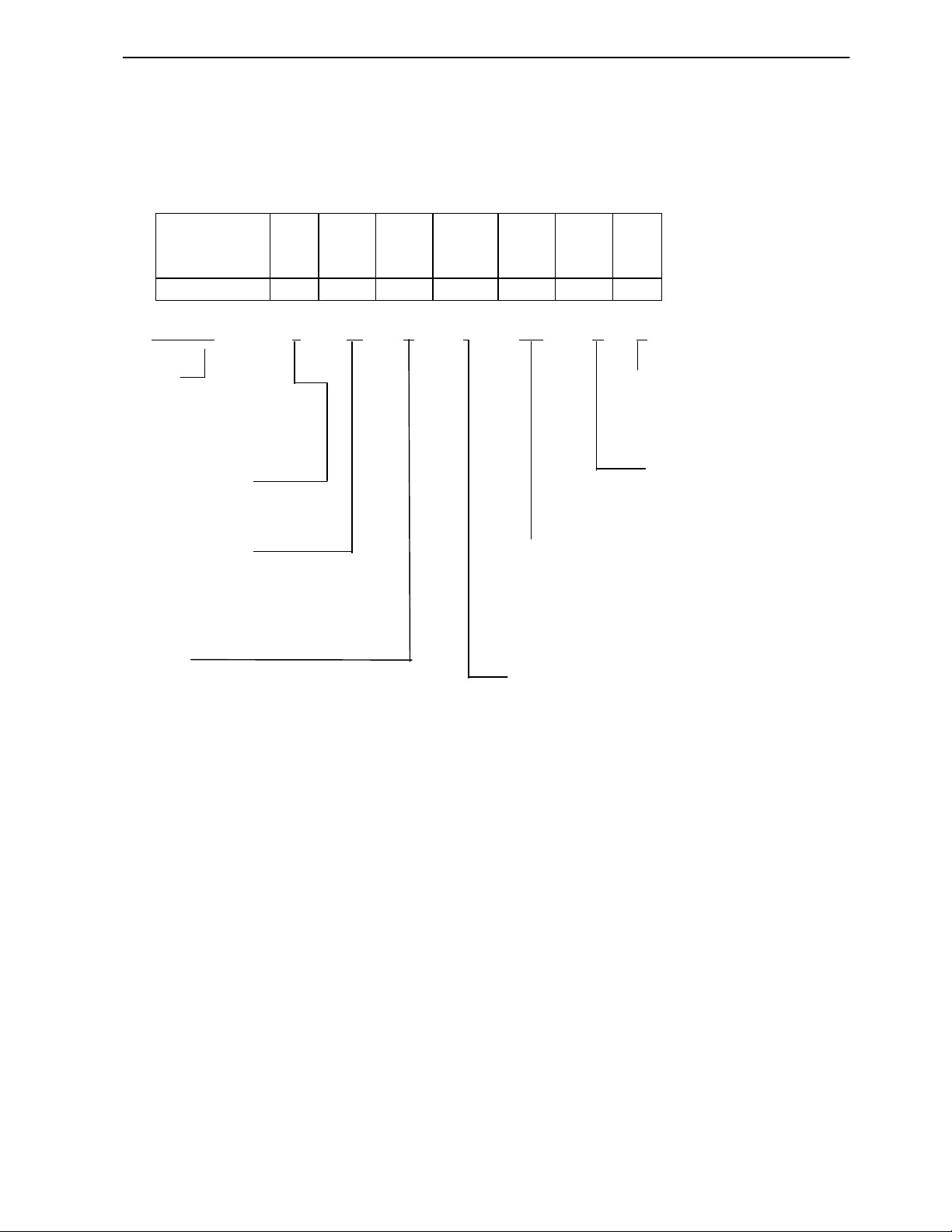
Printer types are classified according to the system shown below.
iDP 3540 F 23 P J 120 G B
P 28 R F 220 N
40 X 240 I
Idp 3541 F
IDP 3540 – F 23 R J 120 – G B
Model Memory Back-up
IDP3540 B: With Back-up
IDP3541: With Auto Cutter N: Without Backup
Paper feed system More
F: Friction feed G: Graphic
P: Pin feed I: Character
↑ ↑ ↑ ↑ ↑ ↑
Column capacity Power source
23: 23 Columns / 230 dots (DP-610) 120: AC 120V
28: 28 Columns / 280 dots (DP-612) 220: AC 220V
40: 40 Columns / 400 dots (DP-617G) 240: AC 240V
40: 40 Columns / 360 dots (DP-614)
Interface
P: Parallel type P Character set*2
R: Serial type R J: Japanese
RS-232C F: International
20mA Current loop
X: RS-422A*1
*1 RS-422A interface specifications are not included in this manual.
*2 The difference is ROM version only.
CITIZEN 7/48

iDP-3540/41 User’s Manual
3. Specifications
3.0 inch.(W) x 3.0 inch.(Dia.)
3.0 inch.(W) x 3.0 inch.(Dia.)
X: Serial interface (RS-422A)
3-1. General Specifications
Item iDP3540F iDP3540P iDP3541
1 Print Method Bidirectional serial dot impact method
2 Character 7 x 7 dots (incl. Half-dot)
composition
Character Printer DP-610: 23 columns 230 dots/line
3 number per DP-612: 28 columns 280 dots/line
line DP-614: 40 columns 360 dots/line
DP-617G: 40 columns 400 dots/line
Printer DP-610: 23 columns approx 4.0 line/sec.
4 Print speed DP-612: 28 columns approx 3.0 line/sec.
DP-614: 40 columns approx 3.0 line/sec.
DP-617G: 40 columns approx 2.4 line/sec.
Printer DP-610: 23 columns 1.8 x 2.4 mm
5 Character size DP-612: 28 columns 1.5 x 2.4 mm
DP-614: 40 columns 1.36 x 2.4 mm
DP-617G: 40 columns 1.2 x 2.4 mm
6 Line pitch Character type: 4.23 mm (1/6 inch.)
Graphic type: 2.82 mm (1/9 inch.)
Paper roll Fan fold paper Paper roll
7 Paper size 76 x 0.5 mm(W) x 80
mm(Dia.)
P: Parallel interface (8 bit)
8 Interface R: Serial interface (RS-232C, 20mA current loop)
76 ~ 89 mm 76 x 0.5 mm(W) x 80
3.0 ~ 3.5 inch.
mm(Dia.)
9 Input buffer 7K bytes or 2 lines buffer*1
Input buffer B type: Duration of back-up, More than 24 hours.*2
10 back-up (after 10 minutes operation)N type: Without back-up
11 Paper end Buzzer and PE signal None Buzzer and PE signal
detection
12 Ribbon cassette Two color (Black and Red) IR-61R/B*3
13 Auto cutter Without With cutter
(Parallel cut / Full cut)
Cash drawer & Cash drawer: Use the drawer solenoid voltage 24V, register over 36 ohms.
14 Winder Winder: Use Model CBM-AW-3.
connector
15 Power voltage 120V ± 10% 60 Hz / 220V ± 10% 50/60 Hz / 240V ± 10% 50/60 Hz
16 Power consump. Max. 30W, Av. 10W
17 Net weight Approx. 2.8kg. Approx. 3.0kg.
18 External Refer to section 17
dimensions
Operation temp.
19
0 ~ 40°C /32 ~ 104°F
CITIZEN 8/48

iDP-3540/41 User’s Manual
*1 Input buffer can be selected by setting the DIP switch.
*2 However, when the input buffer is set for two lines, back-up of graphic data is not possible.
*3 Single color cassette ribbon is available as option.
Black print: IR-61B
Purple print: IR-61P
CITIZEN 9/48
iDP-3540/41 User’s Manual
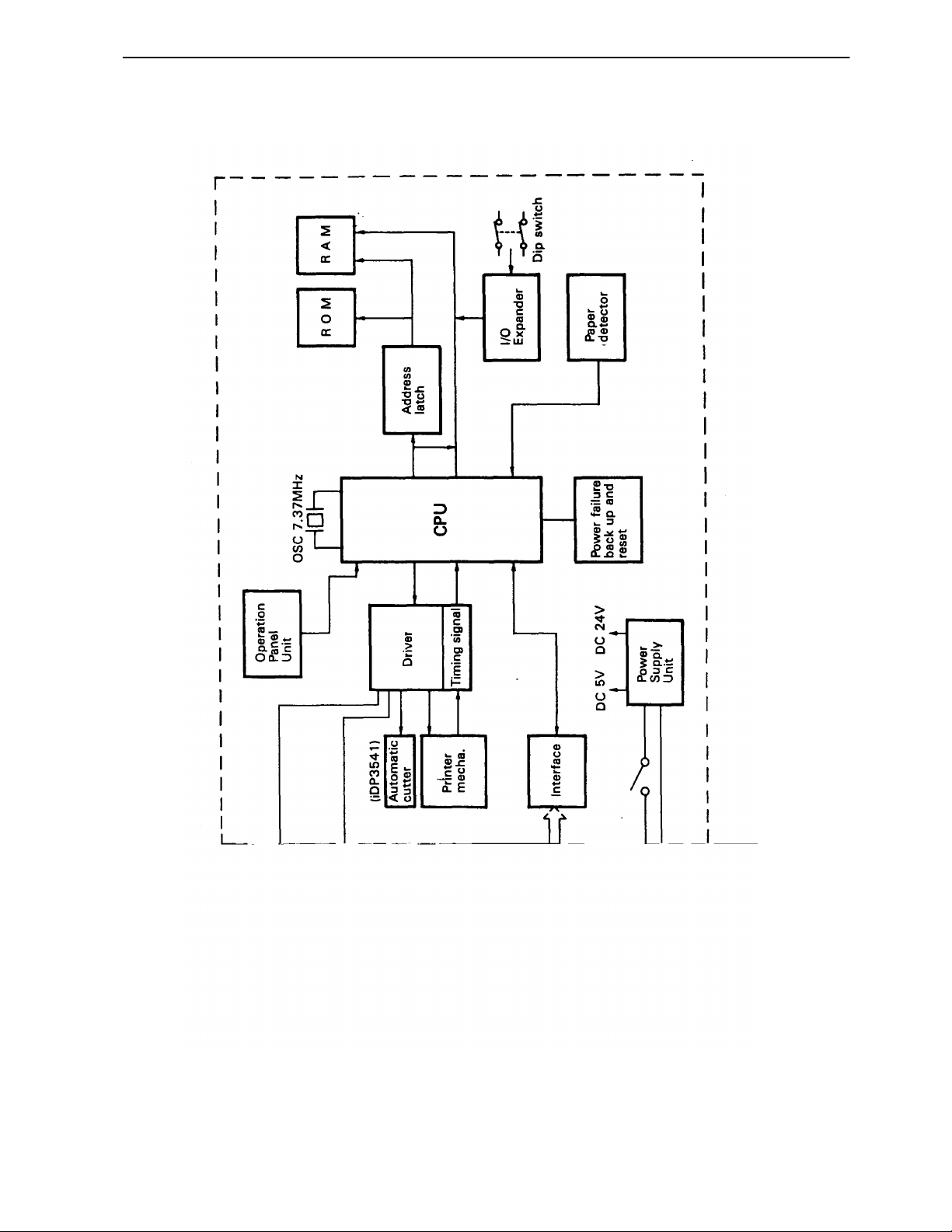
4. Block Diagram
CITIZEN 10/48
iDP-3540/41 User’s Manual
5. External Appearance and parts Description
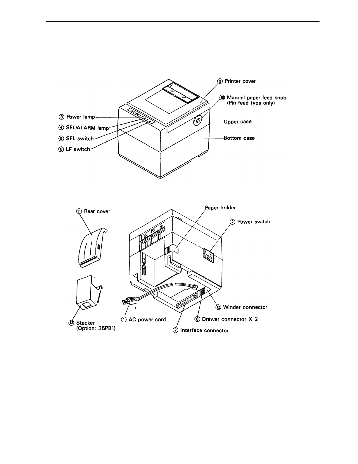
5-1. External appearance and parts names Model : iDP3540
CITIZEN 11/48
iDP-3540/41 User’s Manual
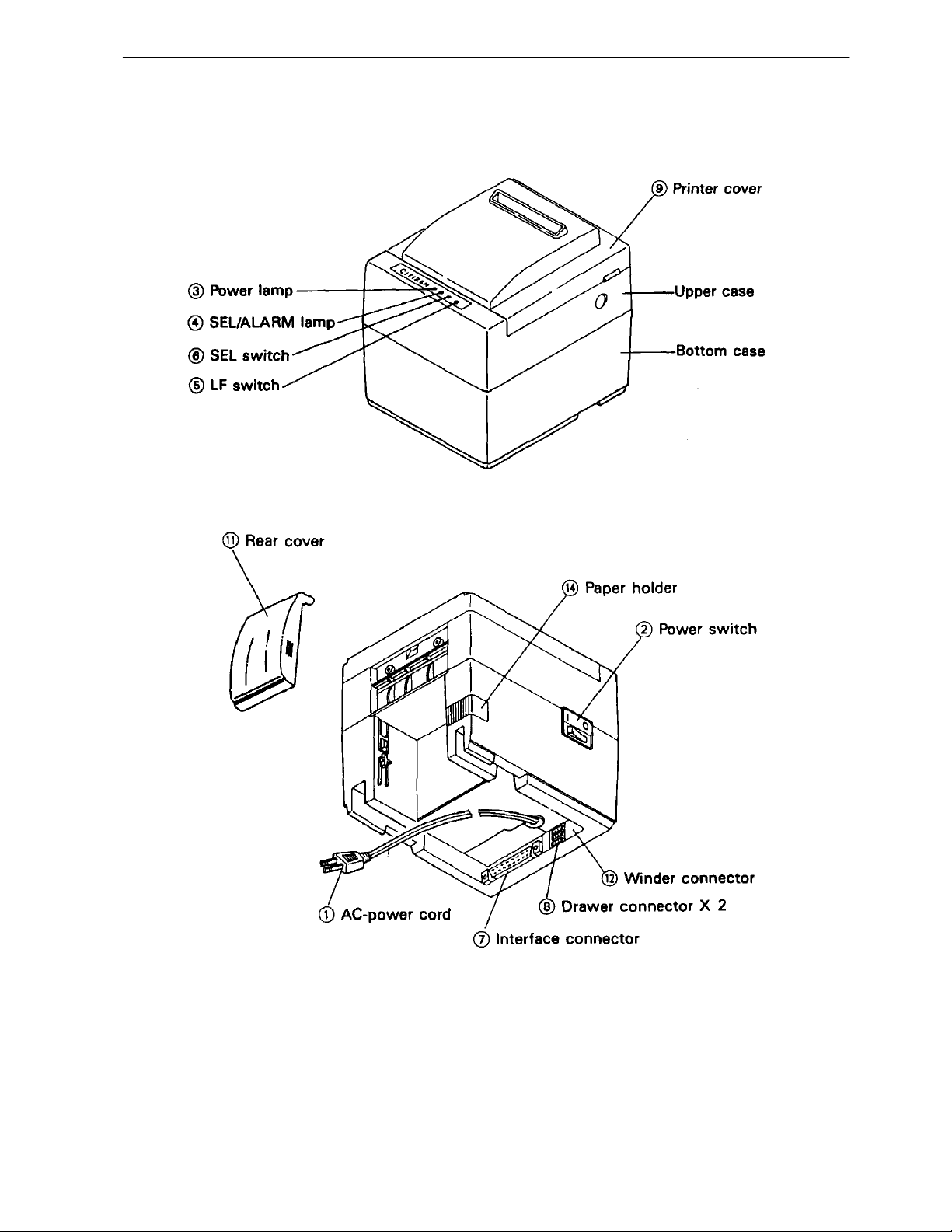
5-2. External appearance and parts names Model : iDP3541
CITIZEN 12/48

iDP-3540/41 User’s Manual
5-3. Parts Descriptions
(1) Power Cord Insert the plug end into an electric outlet.
(2) Power Switch Power is supplied to the printer by turning this switch on.
(3) Power Lamp This lights up when the power switch is “ON” and goes out
when turning “OFF”.
(4) SEL / ALARM Lamp This lights up when the printer is in SELECT state
(ON-LINE) and goes out when in DESELECT state (OFFLINE). The printer can print out the data only when this
lamp is on.
This lamp may blink on the following occasions.
a) When the paper roll in coming to near-end, the SEL /
ALARM lamp keeps blinking at interval of 1.0 second.
In this case, change the roll paper.
b) When the printer is in alarm state, this lamp keeps
blinking at interval of 1/4 second.
Remove the cause for alarm and press the SEL switch.
(or re-switch the power on)
(5) LF Switch Paper feeding is performed when this switch is pressed
(in DESELECT status only), this is used when inserting the
paper and for spacing up etc.
(6) SEL Switch When this switch is pressed, the printer enters SELECT
(ON-LINE) status. When pressed again, the printer enters
DESELECT (OFF-LINE) status.
This switch is also used when clearing an alarm condition.
And if this switch is pressed when printing, the printer
enters DESELECT status, after all the data in the buffer is
printed.
(7) I/F Connector Connects through a cable to a computer etc. Please be
certain that power to both the printer and the computer are
turned off when connection is made.
(8) Cash Drawer Connector To be used to control the P.O.S. cash drawer.
(9) Printer Cover Open when replacing the Ribbon Cassette.
(10) Manual Paper Feed Knob Use to adjust the paper position (Available only on pin
tractor paper feeding model).
(11) Rear Cover Cover for paper roll.
(12) Winder Connector Use Model CBM AW-3
(13) Stacker Basket for fan-fold paper.
CITIZEN 13/48
iDP-3540/41 User’s Manual
6. Preparation
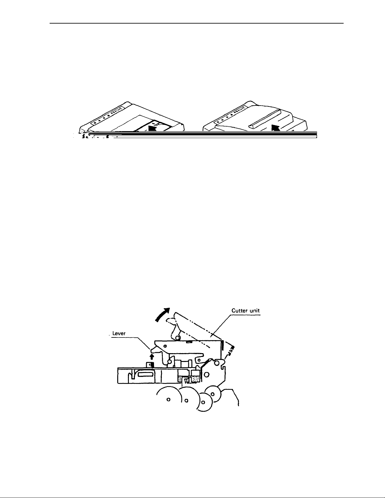
6-1. Inserting / Removing the Printer Cover
Inserting and removing the printer cover as shown in Fig. 1, 2.
Fig. 1 Fig. 2
6-2. Opening and Closing the Cutter Unit (iDP3541)
1) To open the unit, grasp two levers and lift upward.
2) When closing the unit, press downward until it completely lock place.
Fig. 3
CITIZEN 14/48
iDP-3540/41 User’s Manual
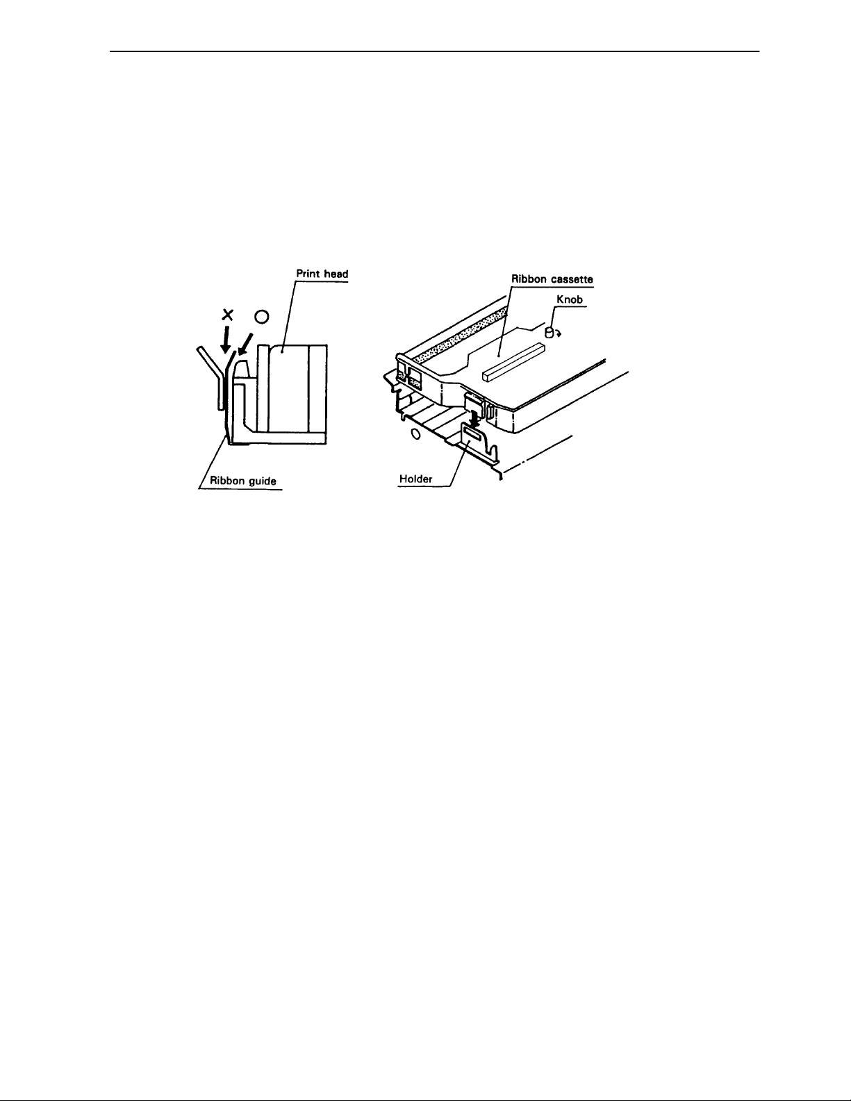
6-3. The Ribbon Cassette Installation
To insert the ribbon, disconnect the power source beforehand. If the printer has been
printing for many hours, be careful not to touch the printer head as it might be hot.
1) Remove the printer cover
2) While inserting the ribbon into the space between the print head and the ribbon guide,
press the cassette into the holder unit it clicks into place. (Ref. to Fig. 4&5)
3) Turn the cassette ribbon knob in the direction of the arrow to take up slack in the ribbon.
Fig. 4 Fig. 5
CITIZEN 15/48
 Loading...