


Citizen iDP-3420, iDP-3423, iDP3421 User Manual

DOT MATRIX PRINTER
MODEL iDP3420
iDP3421
iDP3423
User’s Manual

iDP3420/3421/3423 User’s Manual
Declaration of Conformity
This printer conforms to the following Standards:
Low Voltage Directive 73/23/EEC, 93/68/EEC and the EMC Directive 89/336/EEC,
92/31/EEC, 93/68/EEC.
LVD : EN60950
EMC : EN55022
Class A
EN61000-3-2
EN61000-3-3
EN55024
This declaration is applied only for 230V model.
CITIZEN is a registered trade mark of CITIZEN WATCH CO., LTD., Japan
CITIZEN es una marca registrada de CITIZEN WATCH CO., LTD., Japón
ESC/POS and EPSON are a trademark and registered trademark of SEIKO EPSON CORPORATION
Star is a registered trademark of Star Micronics Corporation
Windows is a registered trademark of Microsoft Corporation
CITIZEN

iDP3420/3421/3423 User’s Manual
IMPORTANT SAFETY INSTRUCTIONS
• Read all of these instructions and save them for future reference.
• Follow all warnings and instructions marked on the product.
• Unplug this product from the wall outlet before cleaning. Do not use liquid or aerosol cleaners. Use
a damp cloth for cleaning.
• Do not use this product near water.
• Do not place this product on an unstable cart, stand or table. The product may fall, causing serious
damage to the product.
• Slots and openings on the back or bottom of the case are provided for ventilation. To ensure reliable
operation of the product and to protectit from overheating, do not block or coverthese openings. The
openings should never be blocked by placing the product on a bed, sofa, rug of other similar surface.
This product should never be placed near or over a radiator or heater. This product should not be
placed in an built-in installation unless properventilation is provided.
• This product should be operated from the type of power source indicated on the marking label. If you
re not sure of the type of power available, consult your dealer or local power company.
• Do not allow anything to rest on the power cord. Do not place this product where the cord will be
walkedon.
• If an extension cord is used with this product, make sure that the total of the ampere ratings of the
products plugged into the extension cord does not exceed the extension cord ampere rating. Also,
make sure that the total of all products plugged into the wall outlet does not exceed 15 amperes.
• Never push objects of any kind into this product through cabinet slots as they may touch dangerous
voltage points or short out parts that could result in a risk of fire or electric shock. Never spill liquid
of any kind on the product.
• Except as explained elsewhere in this manual, do not attempt to service this product by yourself.
Opening and removing the covers that are marked “Do Not Remove” may expose you to dangerous
voltage points or other risks. Refer all servicin gon those compartments to service personnel.
• Unplug this product from the wall outlet and refer servicing to qualified service personnel under the
following conditions:
A. When the power cord or plug is damaged or frayed.
B. If liquid has beenspilled into the product.
C. If the product has been exposed to rain or water.
D. If the product does not operate normally when the operating instructions are followed. Adjust only
those controls that are covered be the operating instructions since improper adjustment of other
controlsmayresultindamageandwilloftenrequireextensiveworkbyaqualifiedtechnicianto
restore the product to normal operation.
E. If the product has been dropped or the cabinet has been damaged.
F . If the product exhibits a distinct change in performance, indicating a need for service.
• Please keep the poly bag which this equipment is packed in away from children or t hrow it away to
prevent children from putting it on. Putting it on may cause suffocation.
CITIZEN

iDP3420/3421/3423 User’s Manual
WICHTIGE SICHERHEITSANWEISUNGEN
• Lesen Sie die nachfolgenden Anweisungen sorgfältig durch und bewahren Sie sie auf.
• Befolgen Sie alle auf dem Drucker vermerkten Hinweise und Anweisungen. Vor dem Reinigen
grundsätzlich Stecker aus der Steckdose ziehen. Keine Flüssigkeiten oder Aerosolreiniger benutzen.
Nut mit einemfeuchten Tuchabwischen.
• Der Drucker darf nicht in der Nähe von Wasser aufgestellt werden.
• Drucker nicht auf einem unstabilen Wagen, Stand oder Tisch aufstellen. Der Drucker könnte
herunterfallen und dabel beschädigt werden.
• Schlitze und Öffnungen im Gehäuse, in der Rückwand und im Boden dienen der Belüftung. Sie
dürfen keinesfalls zugedeckt oder blockiert werden, da sich der Drucker sonst überhitzt. Drucker
nicht auf ein Bett, Sofa, T eppich oder dergleichen stellen. Drucker nicht in der Nähe eines
Heizkörpers aufstellen. Drucker darf nicht eingebaut werden, falls nicht für ausreichende Belüftung
gesorgt ist.
• Drucker nur mit der auf dem Typschild a ngegebenenSpannung betreiben. Wenn Sie s ich nicht sicher
sind, fragen Sie ihren Händler oder ihr zuständiges Elektrizitätswerk.
• Nichts auf das Stromanschlußkabel stellen. Kabel muß so verlegt werden, daß man nicht darauftreten
kann.
• Ein etwaiges Verlängerungskabel muß der Stromstärke aller daran angeschlossenen Geräte entsprechen.
• Keine Gegenstände in die Gehäuseschlitze schieben.
• Drucker darf nur da gewartet werden, wo im Handbuch angegeben, Öffnen und. Abnehmen von
Abdeckungen, die mit “Do not remove” gekennzeichenet sind, könnte gefährliche spannungführende
Stellen oder sonstige Gefahrenpunkte freilegen. Die Wartung solcher Stellen darf grundsätzlich nur
von besonders ausgebildetem Fachpersonal vorgenommen werden.
A.Wenn das Stromanschlußkabel oder der Stecker beschädigt oder durch-gescheuert ist.
B. Wenn Flüssigkeit auf dem Drucker verschüttet wurde.
C.W en nder Drucker im Regen gestand en hat oder Wasser darauf verschüttet wurde.
D.We nn der Drucker trotz genauer Befolgung der Betriebsvorschriften nicht richtig arbeitet. Nur die
in der Bedienungsanleitung angegebenen Einstellungen vornehmen. Ein Verstellen anderer
Bedienungselemente könnte den Drucker beschädigen und macht umständliche Arbeiten eines
qualifizierten Technikers erforderlich, um den Drucker Wieder auf den normalen Betrieb
einzustellen.
E. Wenn der Drucker heruntergefallen ist oder das Gehäuse beschädigt wurde.
F. Wenn der Drucker in seiner Leistung nachläßt.
• Bitte halten Sie den Kunststoffbeutel, in den die Ware verpackt ist, von Kindern entfernt, oder werfen
Sie ihn weg, damit er nicht in die Hande von Kindern gerät. Das Überstülpen des Beutels kann zum
Ersticken führen.
Lärmemission kleiner 70dBA
CITIZEN

iDP3420/3421/3423 User’s Manual
IMPORTANT: This equipment generates, uses, and can radiate radio frequency energy and if not
installed and used in accordance with the instruction manual, may cause interference to radio
communications. It has been tested and found to comply with the limits for a Class A computing device
pursuant to Subpart J of Part 15 off FCC Rules, which are designed to provide reasonable protection against
such interference when operated in a commercial environment. Operation of this equipment in a
residential area is likely to cause interference, in which case the user at his own expense will be required to
take whatever measures may be necessary to correct the interference.
CAUTION: Use shielded cable for this equipment.
Sicherheitshinweis
Die Steckdose zum Anschluß dieses Druckers m uß nahe dem Grät angebracht und leicht zugänglich sein.
For Uses in Canada
This digital apparatus does not exceed the class A limits for radio noise emissions from digital, apparatus,
as set out in the radiointerference regulationsof the Canadian departmentof communications.
Pour L’utilisateurs Canadiens
Cet appareil numérique ne dépasse pas les limites de carégorie a pour les émissions de bruit radio émanant
d’appareils numériques, tel que prévu dans les réglements sur l’interférence radio du départment Canadien
des communications.
CITIZEN

iDP3420/3421/3423 User’s Manual
<CAUTIONS>
1. Prior to using the equipment, be sure to read this User's Manual thoroughly. Please keep it handy for reference
whenever it may be needed.
2. The information contained hereinmay be changed without prior notice.
3. Reproduction of part or all of this User's Manual without permission is strictly prohibited.
4. Never service, disassemble, or repair parts that are not mentionedin this User's Manual.
5. Note that we will not be responsible for damages attributable to a user's incorrect operation/ handling or an
improper operating environment.
6. Operate the equipment only as described in this User's Manual; otherwise accidents or problems may result.
7. Data are basically temporary; they cannot be stored or saved permanently or for a long time. Please note that
we will not be responsible for damages or losses of profit resulting from losses of the data attributable to
accidents, repairs, tests, and so on.
8. If you have any questions or notice any clerical errors or omissions regarding the information in this manual,
please contact our office.
9. Please note that, notwithstanding Item 8 above, we will not be responsible for any effects resulting from
operation of the equipment.
CITIZEN
iDP3420/3421/3423 User’s Manual
SAFETY PRECAUTIONS ----- BE SURE TO OBSERVE
In order to prevent hazards to an operator or other persons and damage to property, be sure to observe the following
precautions.
• The following describes the degrees of hazard and damages that can occur if the given instructions are
neglected or the equipment is incorrectly operated.
WARNING Negligence of this precaution may result in death or serious injury.
CAUTION Negligence of this precaution may result in injury or damage to property.
This is an illustration mark used to alert your attention.
This is an illustration mark used to indicate such information as an instruction or the like.
CITIZEN

iDP3420/3421/3423 User’s Manual
WARNING
• Never handlethe equipment in the followingmanners, as itmay break, become out oford er, or overheat
causing smok eand resulting in fire or electric sho c k.
If the equipment is used in an abnormal condition, such as when broken, then problems, smoke
emission, abnormal odor/noise, and fire can result. If an abnormal condition exists, be sure to turn off
the power, disconnect the power plug from a plug socket, and contact our dealer. Never repair the
equipment on your own - it is very dangerous.
• Do not allow the equipment to receive a strong impact or shock, such as kicking, stomping, hitting,
dropping, and the like.
• Install the equipment in a well-ventilated place. Do not use it in such amanner that its ventilation port
will be blocked.
• Do not install the equipment in a place like a laboratory where chemical reactions are expected, or in a
place where salt or gases are contained in the air.
• Do not connect/disconnect a power cord or a data cable, while holding the cable. Do not pull, install,
use, or carry the equipment in sucha manner that force will be applied to the cables.
• Do not drop or insert any foreignsubstances, such as clips or pins, into the equipment.
• Do not spill any liquid or spray any chemical-containing liquid over the equipment. If any liquid is
spilled on it, turn off the power, disconnect the power cable and power cord from the plug socket, and so
on, and contact our dealer.
• Do not disassemble or remodel the equipment. Negligence of this may cause fire or
electric shock.
• Should you drop or break this AC adapter by any chance, unplug it immediately and contact our office.
Using it in that conditionmay result in fire or electric shock.
• Should water enter inside the equipment by any chance , unplug it and contact our office. Using it in
that cond ition may result in fire or electric shock.
• Use the equipment only with the specified commercial power supply. Negligence of this may result i n
fire, electric shock, or problems.
• Do not damage, break, process, bend/pull by force, twist, or bundle an AC adapter cord. Also, do not
put a heavy substance on it or heat it. The AC adapter could be broken, resulting in fire, electric shock,
or trouble. If the AC adapter cord is damaged, contact our office.
• Do not connect/disconnect the AC adapter with wet hands. It may result in electric shock or other
problems.
• Do not overload a single electrical outlet, using a table tap or a current tap socket. It may result in fire
or electric shock.
• An equipment packing bag must be discarded or kept away from children. A child can suffocate if the
bag is placed over the head.
CITIZEN

iDP3420/3421/3423 User’s Manual
PRECAUTIONS FOR I NSTALLATION
• Do not use or store the equipment in a place exposed to fire, moisture, or direct sunlight, or in a place
near a heater or a thermal device where the prescribed operating temperature and humidity are not met,
or in a place exposed to much oil, iron powder, or dust. The equipment may become out of order, emit
smoke, or catch fire.
• Do not install the equipment in a place like a laboratory where chemical reactions are expected, or in a
place where salt or gases are contained in the air. There is a danger of fire or electric shock.
• Do not put any object on the printer. It may cause trouble.
• Do not use the equipment near a radio or TV receiver. Do not share the power from a plug socket a
radio or TV receiver is connected to. It may cause a reception problem.
• Use the equipment only at the specified voltage and frequency. Otherwise, it may emit smoke and
catch fire or cause other problems.
• Confirm that a plug socket used for connection has sufficient capacity.
• Do not overload a single electrical outlet in connecting the power cable. It may result in the cable
catchingfire or a power outage. Also, do not stampor put any object on the cable.
• Never connect a grounding cable to a gas pipe. There is a danger of explosion. When connecting or
disconnecting the grounding cable, be sure to disconnect the power plug from the plug socket.
• When connecting/disconnecting the cables, be sure to turn off the power first, including the connected
side, and then connect/disconnect them, holding a plug and a connector. Do not pull or carry the
equipment with a load applied to the cable.
• Connect a connector cable securely. If a reverse-polarity connection is made, internal elements may
be broken or a mating device may be adversely affected.
• Use a shielding wire or twisted pair wire for a signal line, in order to minimize noise effect. Avoid
connecting to a device that is likely to generate noise.
• When a drawer kick connector is provided, do not connect any device other than the prescribed solenoid
specifications. Negligence of this could cause trouble.
• Use the equipment in an environment where there is a plug socket near the main body and you can
easily disconnect the power plug from it, to shutoff the power .
• When the equipment will not be used for a long period of time, unplug it.
• When transporting the equipment, remove the rolled paper from it.
• Install the equipment on a flat, stable desk in a well-ventilated place free from vibrations. (Do not
block the ventilation port.)
CITIZEN

iDP3420/3421/3423 User’s Manual
PRECAUTIONS FOR HANDLING
Do not handle the equipmen t in the following manners, because problems may result.
• Do not use a power supply other than the specified AC adapter.
• Do not print when there is no recording paper or ink ribbon set in the equipment. The print head may
be damaged
• Be carefulnot to drop foreign substances, such as clips,pins, and screws,into the mainbody.
• Do not spill any liquid or spray any chemical-containing liquid over the equipment.
• Do not stamp on, drop, hit, or give a strong shock to the equipment.
• Never use a pointedobject, such as a pen, to operate the operation panel.
• Do not use Scotch tape to fasten paper together for continuous use.
• Never pull the set paper forcibly. When opening/closingtheprinter cover, take care that thepaper will
not be caught.
To PreventInjurya nd Spreadingof Damage
• Do nottouch the printing part of the print head.
• When turning on the power, do not touch the moving parts, such as a cutter and gear inside the main
body, or electric parts.
• Be careful to avoid bodily injure or damaging other objectswithan edge of sheet metal.
• Should any error occur while operating the equipment, stop it immediately and disconnect the power
plug from the plug socket.
• Should a problem occur, leave solving it to our serviceman. Do not disassemble the equipment on
your own.
• When opening/closing the cover, and so on, be careful not to catch your hand or finger on the
equipment.
CITIZEN

iDP3420/3421/3423 User’s Manual
DAILY MAINTENANCE
• Priortostartingmaintenancework,besuretoturnoffthemainbody.
• Use a dry soft cloth to wipe off stains and dust from the surfaces of the main body case. For severe
soiling, dip the cloth in water and wring it, for wiping off the soil. Never use org anic solvents, such as
alcohol, thinner, trichlene, benzene, ketone, or chemical dusters.
• If the equipment is contaminated with paper powder, use a soft brush to clean it.
CITIZEN

iDP3420/3421/3423 User’s Manual
CONTENTS
1. OUTLINE.............................................................................................................................................................. 1
1.1 Features......................................................................................................................................................... 1
1.2 Unpacking..................................................................................................................................................... 1
2. BASIC SPECIFICATIONS..................................................................................................................................2
2.1 Model Classifications..................................................................................................................................... 2
2.2 BasicSpecifications....................................................................................................................................... 3
2.3 PaperSpecifications....................................................................................................................................... 4
2.3.1 RecommendedPaper ........................................................................................................................... 4
2.3.2 Printing Position.................................................................................................................................. 4
2.3.3 Cutter Layout...................................................................................................................................... 4
3. OUTER APPEARANCE ANDCOMPONENT PARTS....................................................................................5
3.1 iDP3420 ........................................................................................................................................................ 5
3.2 iDP3421 ........................................................................................................................................................ 6
3.3 iDP3423 ........................................................................................................................................................ 7
4. OPERATION.........................................................................................................................................................8
4.1 Connecting the Power Cord............................................................................................................................ 8
4.2 Connecting Interface Cable............................................................................................................................ 9
4.3 Attaching the Ferrite Core to the Interface Cable.................................................................................. .........10
4.4 Connecting Drawer Kick-Out Connector.......................................................................................................11
4.5 Opening/Closing the Auto Cutter (iDP3421/3423)......................................................................................... 11
4.6 Setting the Cassette Ribbon...........................................................................................................................12
4.7 Inserting the Paper........................................................................................................................................13
4.7.1 Inserting the Paper (iDP3420/3421)....................................................................................................13
4.7.2 Inserting the Paper Roll (Duplicable 2-sheet Paper)(iDP3423).............................................................15
4.7.3 Removing the Wound Paper Roll(iDP3423)........................................................................................16
4.8 Adjusting the Paper Near End Sensor ............................................................................................................16
4.9 How to Remove Remaining Paper Roll .........................................................................................................17
4.10 Removing PaperJam.....................................................................................................................................17
4.11 Unlocking the Cutter(iDP3421/3423)............................................................................................................18
4.12 Operation Paneland Display of Error............................................................................................................19
4.13 Operation Flow at Power-on..........................................................................................................................20
CITIZEN

iDP3420/3421/3423 User’s Manual
4.14 Print Duty.....................................................................................................................................................20
5. DIP SWITCHSETTING.................................................................................................................................... 21
5.1 Location of DIP Switch .................................................................................................................................21
5.2 DIP Switches Setting.....................................................................................................................................22
6. PRESET JUMPER SETTING........................................................................................................................... 24
6.1 Location ofPreset Jumper.............................................................................................................................24
6.2 Preset Jumper Table......................................................................................................................................24
7. MODE SETTING METHOD ............................................................................................................................ 25
8. INPUT BUFFER BACKUP FUNCTION ......................................................................................................... 26
8.1 Buffer Size....................................................................................................................................................26
8.2 Input Buffer Backup......................................................................................................................................26
8.3 Clearing the Input Buffer...............................................................................................................................26
9. PARALLEL INTERFACE.................................................................................................................................27
9.1 Specification s ...............................................................................................................................................27
9.2 Connector'sPin Configuration.......................................................................................................................27
9.3 Input and Output Signals...............................................................................................................................27
9.3.1 Input and Output Signals....................................................................................................................28
9.3.2 Electrical Characteristics....................................................................................................................29
9.3.3 Timing Chart......................................................................................................................................30
9.3.4 Data Receiving Control ......................................................................................................................30
10. SERIAL INTERFACE...................................................................................................................................... 31
10.1 Specification s ...............................................................................................................................................31
10.2 Connector'sPin Configuration.......................................................................................................................32
10.3 Input and Output Signals...............................................................................................................................33
10.3.1 Input and Output Signals....................................................................................................................33
10.3.2 Data Configuration.............................................................................................................................35
10.3.3 Error Detection...................................................................................................................................36
10.3.4 Data Receiving Control......................................................................................................................36
10.3.5 Buffering............................................................................................................................................36
10.3.6 Electrical Characteristics....................................................................................................................37
CITIZEN

iDP3420/3421/3423 User’s Manual
11. DRAWER KICK-OUT CONNECTOR........................................................................................................... 38
11.1 Specifi cations of Drawer Kick-Out Connector ...............................................................................................38
11.2 Connector's Pin Configuration.......................................................................................................................38
11.3 Drive Circuit.................................................................................................................................................38
12. MAINTENANCE AND SERVICE.................................................................................................................. 39
13 PRINT CONTROL FUNCTIONS................................................................................................................... 40
13.1 CBMMode...................................................................................................................................................40
13.1.1 Command List....................................................................................................................................40
13.1.2 Description of Items .........................................................................................................................41
13.2 Star Mode .....................................................................................................................................................59
13.2.1 Command List....................................................................................................................................59
13.3 ESC/POS Mode............................................................................................................................................90
13.3.1 Command List....................................................................................................................................90
14. CHARACTER CODES TABLE......................................................................................................................112
14.1 CBM(Japanese)..........................................................................................................................................112
14.2 CBM(International)....................................................................................................................................113
14.3 Star (Japanese)............................................................................................................................................114
14.4 Star (International)...................................................................................................................................... 115
14.5 Codepage PC437 (USA,European Standard)................................................................................................116
14.6 Codepage Katakana (Japanese)....................................................................................................................117
14.7 Codepage PC850 (Multilingual)..................................................................................................................118
14.8 Codepage PC860 (Portuguese).................................................................................................................... 119
14.9 Codepage PC863 (Canadian-French)...........................................................................................................120
14.10 Codepage PC865 (Nordic)...........................................................................................................................121
14.11 CodepagePC852 (Eastern Europe)..............................................................................................................122
14.12 Codepage PC866 (Russian).........................................................................................................................123
14.13 Codepage PC857 (Turkish) .........................................................................................................................124
14.14 Windows Codepage ....................................................................................................................................125
14.15 International Character CodesTable............................................................................................................ 126
APPENDIX 1. BLOCK DIAGRAM................................................................................................................. 127
APPENDIX 2. OUTLINE DRAWING for iDP3420........................................................................................ 128
APPENDIX 3. OUTLINE DRAWING for iDP3421........................................................................................ 129
APPENDIX 4. OUTLINE DRAWING for iDP3423........................................................................................ 130
CITIZEN

iDP3420/3421/3423 User’s Manual
<<< German >>>
4. BETRIEB ........................................................................................................................................................... 138
4.1 Anschluß des Netzkabels ..................................................................................................................................138
4.2 Anschluß des Schnittstellenkabels ....................................................................................................................139
4.3 Anbringen des Ferritkerns am Schnittstellenkabel............................................................................................140
4.4 Anschluß des Schubladenausschubsteckers ......................................................................................................141
4.5 Öffnen/Schließen des automatischen Schneidemechanismus ...........................................................................141
4.6 Einlegen der Farbbandkassette..........................................................................................................................142
4.7 Einlegen des Papiers .........................................................................................................................................143
4.7.1 Das Papier (iDP3420/3421) einlegen.....................................................................................................143
4.7.2 Einlegen der Papierrolle (doppellagiges Durchschlagpapier) (iDP3423) ..............................................145
4.7.3 Herausnehmen der vollen Papierrolle (iDP3423) ..................................................................................146
4.8 Ausrichten des Papierrestsensors ......................................................................................................................146
4.9 Herausnehmen der Restpapierrolle ...................................................................................................................147
4.10 Beseitigung von Papierstaus..............................................................................................................................147
4.11 Initialisierung des Schneidemechanismus(iDP3421/3423) ...............................................................................148
4.12 Bedienfeld und Fehleranzeigen.........................................................................................................................149
4.13 Betriebsfluß beim Einschalten ..........................................................................................................................151
4.14 Drucklvorgang...................................................................................................................................................151
5. DIP SCHALTER-EINSTELLUNG ................................................................................................................. 152
5.1 Lage der DIP-Schalter.......................................................................................................................................152
5.2 DIP-Schalter-Einstellungen...............................................................................................................................153
6. EINSTELLUNG DER VORWAHL-JUMPERSTECKER............................................................................ 155
6.1 Lage der Vorwahl-Jumperstecker......................................................................................................................155
6.2 Vorwahl-Jumperstecker-Tabelle........................................................................................................................155
7. METHODE FÜR MODUSEINSTELLUNG .................................................................................................. 156
12. WARTUNG UND KUNDENDIENST ............................................................................................................. 157
.
CITIZEN

iDP3420/3421/3423 User’s Manual
1. OUTLINE
This is a small-size dot impact printer developed for various data communication terminals, POS terminals,
kitchen-use printers, bank card, terminals, and so on.
Its abundant built-in features allow you to widely use this printer for different applications. Prior to using it,
read and understand thismanual thoroughly.
1.1 Features
(1) Small size, light weight, and low price
(2) High-speed print (Bi-directional)
(3) Red andblack print
(4) Very easy paper loading by the auto loading function
(5) Paper end detecting function
(6) Built-inautocutter (ACS-230) (iDP3421)
(7) Built-ina uto cutter and winder (iDP3423)
(8) Built-in power supply
1.2 Unpacking
(1) When unpacking the printe r,confir m that the following parts areprovided.
• Printer body -----1 unit
• Cassette ribbon -----1 piece
• Samplepaper roll -----1 roll
• User'smanual -----1 copy
• Power cord ---- 1 piece
• Ferrite core ---- 1 piece
• Fastener ---- 1 piece
CAUTION : • Install the printer on a flat and stable desk.
• Do not install the printer near a heater or in a place exposed to direct sunlight.
• Do not use the printer in a high-temperature, high-humidity, and contaminated
environment.
• Do not allow dew condensation on the printer. If dew is condensed on it, leave the
power turned off until dew condensation is gone.
1 CITIZEN

2. BASIC SPECIFICATIONS
2.1 Model Classifications
The printer mode l is classified by the following designati on method.
iDP3420 - R F 120
iDP3420/3421/3423 User’s Manual
Supply Voltage
120: For 120 V AC
230: For 230 V AC
Character Set
F: International
Interface
• CBM Mode
R: Serial (RS-232C)
P: Parallel (CENTRONICS Compliant)
• Star Mode
S: Serial (RS-232C)
C: Parallel (CENTRONICS Co mpliant)
• ESC/POS Mode
T: Serial (RS-232C)
I: Parallel (CENTRONICS Compliant)
Model Name
• iDP3420 StandardModel
• iDP3421 WithAuto Cutter
• iDP3423 WithAuto Cutter and Winder
2 CITIZEN
2.2 Basic Specifications
iDP3420/3421/3423 User’s Manual
Model
Item
Printer mechanism DP-410 series (CITIZEN)
Print method Serial dot impactmethod (Bidirectional print)
Print width 64 mm
Print head 9 pins
Print speed Approx. 3 lines/second (At single-color continuous print)
Print columns 40 or 42 columns (Selectable with the DIP switch)
Character size
Character types Alphanumeric, Katakana, International characters, Codepage PC850, PC860,
Linespacing 4.23 mm(1/6 inch) or 2.82(1/9 inch)
Paper
Ink ribbon Special purpose ribboncartridge red/black or single color(Black)
Interface Serial(RS-232C), Parallel(CENTRONICS compliant)
Commandsystem
Print function Provided by operating the on-line, self-test, hex. dump print function power
Input buffer 6 KB or 256 bytes (Selectable with the DIP switch)
Buffer backup function Within 24 hours (After 10 minutes or m ore of printer operation)
Drawer function 2-drawer, 1-drawer switch
Autoloadingfunction Automatically feeds the paper by several lines when it is inserted.
Paper end detection Stops printing when the paper has run out.
Paper near end detection
Autocutter None ACS-230 (Capable of partial and full cut)
Winder None Special purpose winder
Supply voltage 120 V AC +/- 10 %, 50/60 Hz, 120 V AC specialpurpose cord set
Power consumption Not printing: Approx. 10 W , Printing: Approx. 30 W
Weight Approx. 2.4 kg Approx. 2.6 kg Approx. 2.8 kg
Outer dimensions
Operating tempe rature and
hum id ity
Storage temperature and
humidity
Reliability Print head: 80,000,000 characters, Mechanism: MCBF 2,500,000 lines (With
EMI standard Japanese: Vccl Class-A U.S.A.: Fcc Class-A
Safety standard U.S.A., Canada: UL, c-UL Europe: TUV , GS
1.31 mm(W) × 3.1 mm(H)
PC863, PC865, PC852, PC857, and Windows codepage
Minimum paper feed pitch: 1.41 mm(1/18 inch)
Ordinary paper and non-carbon paper: 76 +/- 0.5 mm(W) ×φ83 mm(OD);
Single-sheet paper: 45 to55 kg/1,000 sheets/1,091 × 788 mm;
Copying paper: Non-carbon paper, 1 original + 1 copy, Total thickness 0.2 mm or
less
CBM mode, Star mode, ESC/POS mode
The user can select themode withthe DIP switch and presetjumpers.
switches and LF switch
Stops printing when the paper is running out.(Settable with a command)
230 V AC +/- 10 %, 50/60 Hz, 230 V AC special purpose cord set
0to40°C, 35 to 85 % RH (No dew condensation)
-20 to 60 °C, 10 to 90 % RH (No dew condensation)
single-sheet recommended paper), Auto cutter: 300,000 cuts (With single-sheet
recommended paper)
Europe: EN55022 Class-B CE Marking
iDP3420 iDP3421 iDP3423
164 (W) × 248 (D) ×140 (H) mm
164 (W )×280(D)×183(H)
3 CITIZEN
2.3 Paper Specifications
2.3.1 Recommended Paper
• T ype : Normal paper and non-carbon paper
• Paper width : 76 +/- 0.5 mm
• Paper thickness : Single-she et paper --- 45 to 55 kg/1,000 sheets/1,091 × 788 mm;
• Roll diameter : φ83 mm or less (Normal paper)
• Core : φ12 mm (Inner Diameter),φ18 mm (Outer Diameter)
2.3.2 Printing Position
iDP3420/3421/3423 User’s Manual
Copying paper --- Non-carbon paper, 1 original + 1 cop y,
Total thickness 0 .2 mm or less
φ60 mm or less (Normal paper only for journal) (iDP3423)
φ80 mm or less (Copying paper) (iDP3423)
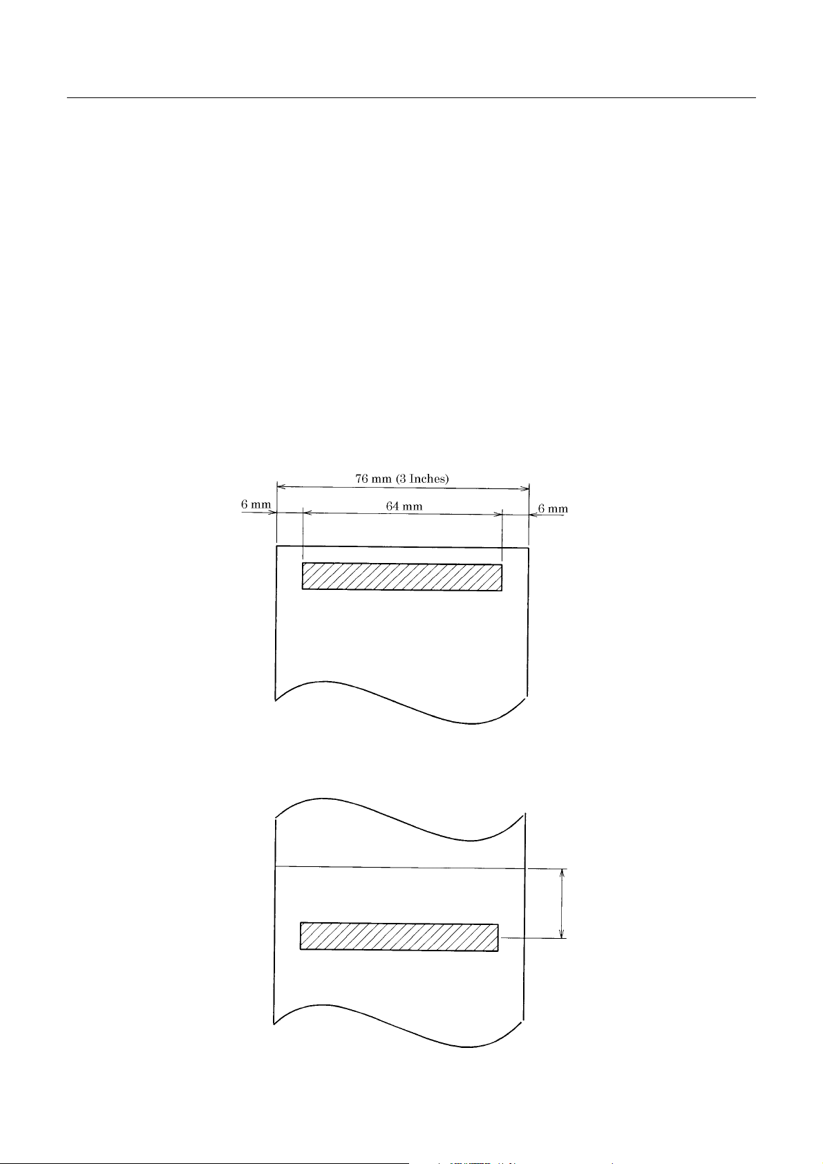
2.3.3 Cutter Layout
iDP3420 tear bar position : Appro x. 21 mm
iDP3421/3423 auto cutter cutting position : Approx. 22 mm
Cuttingposition
iDP3420 : Approx. 21 mm
iDP3421/23 : Approx. 22 mm
4 CITIZEN
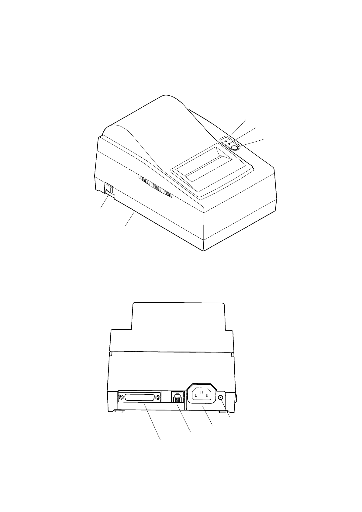
3. OUTER APPEARANCE AND COMPONENT PARTS
3.1 iDP3420
Power Switch
iDP3420/3421/3423 User’s Manual
POWER Lamp
ERROR Lamp
FEED Switch
T op Cover
Drawer Kick-Out Connector
Interface Connector
5 CITIZEN
Grounding Terminal
Power Connector

3.2 iDP3421
iDP3420/3421/3423 User’s Manual
POWER Lamp
ERROR Lamp
FEED Switch
Power Switch
T op Cover
Grounding Terminal
Power Connector
Drawer Kick-Out Connector
Interface Connector
6 CITIZEN
3.3 iDP3423
iDP3420/3421/3423 User’s Manual
POWER Lamp
ERROR Lamp
FEED Switch
Power Switch
T op Cover
Drawer Kick-Out Connector
Interface Connector
7 CITIZEN
Grounding Terminal
Power Connector
iDP3420/3421/3423 User’s Manual
4. OPERATION
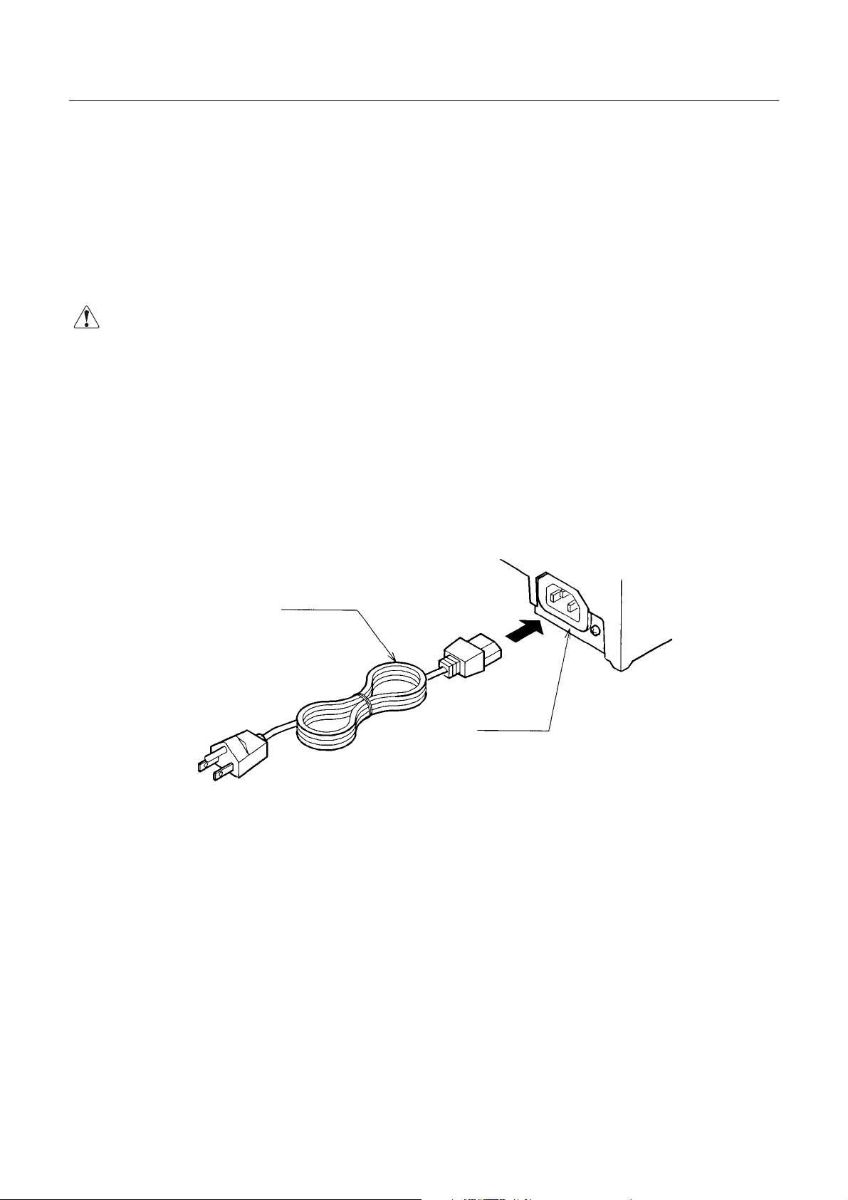
4.1 Connecting the Power Cord
1. Turn off the Power switch.
2. Connect a power cord connector to the power connector located on the back of the printer.
3. Connect a power cord plug to a plug socket where the specified voltage is available.
CAUTIONS : • Use the AC power supply different from theone used for any noise-generating device.
• When disconnecting the power cord, be sure to hold its plug.
• Pulling the power cord could damage it and result in a fire, electric shock, or snapping of
the wire.
• If lightning has occurred in t he nearby area, disconnect the power cord from the plug
socket and refrain from using the printer. A lightning strike could result in a fire or
electric shock.
• When the printer is not used for a long period of time, be sure to disconnect the power
cord from the plug socket for safety.
Power Cord
Power
Connector
8 CITIZEN
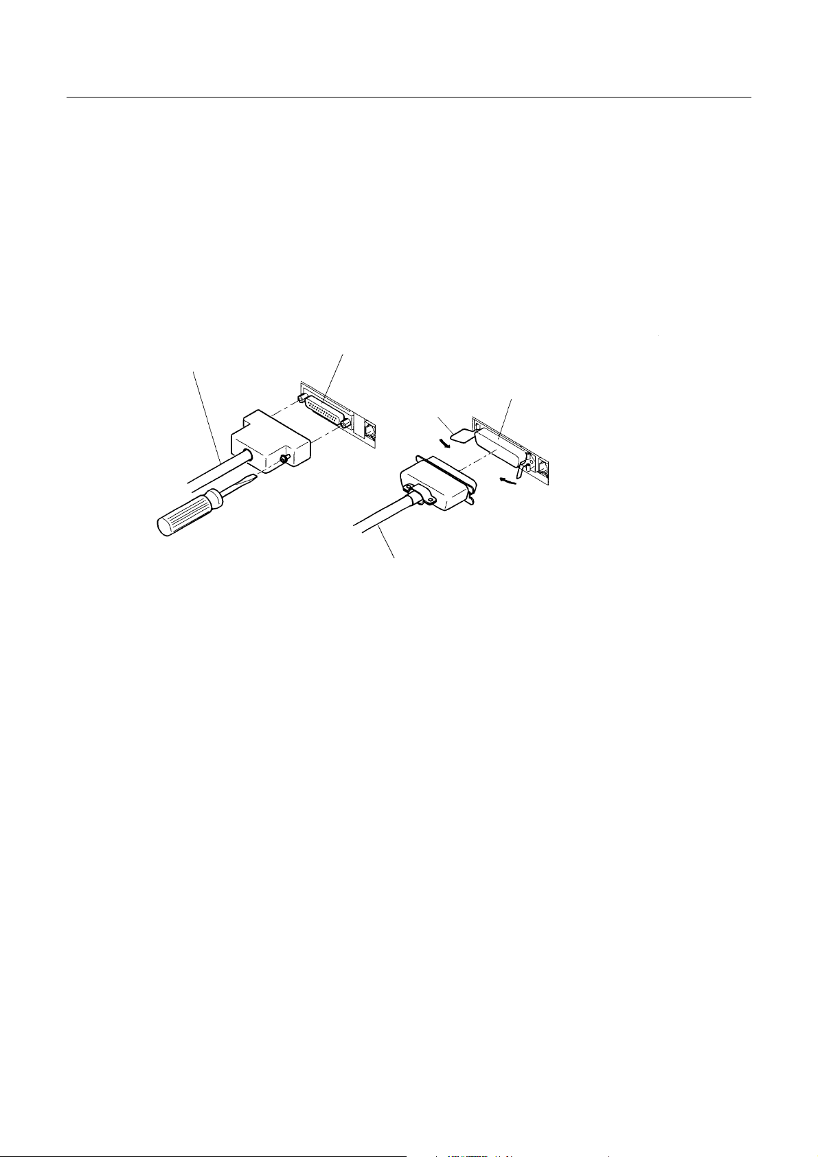
4.2 Connecting the Interface Cable
p
1. Turn off the power. (Mating side included)
2. Check the top and bottom of the cable terminals, and connect to the interface connector.
3. Secure the cable ter minals.
Serial interface : Tightenscrews to secure.
Parallel interface : Turnclamps to secure.
4. Connect the interface cable to thecomputer.
iDP3420/3421/3423 User’s Manual
SerialInterface Cable
Serial Interface Connector
Parallel Interface Connector
Clam
Parallel Interface
9 CITIZEN
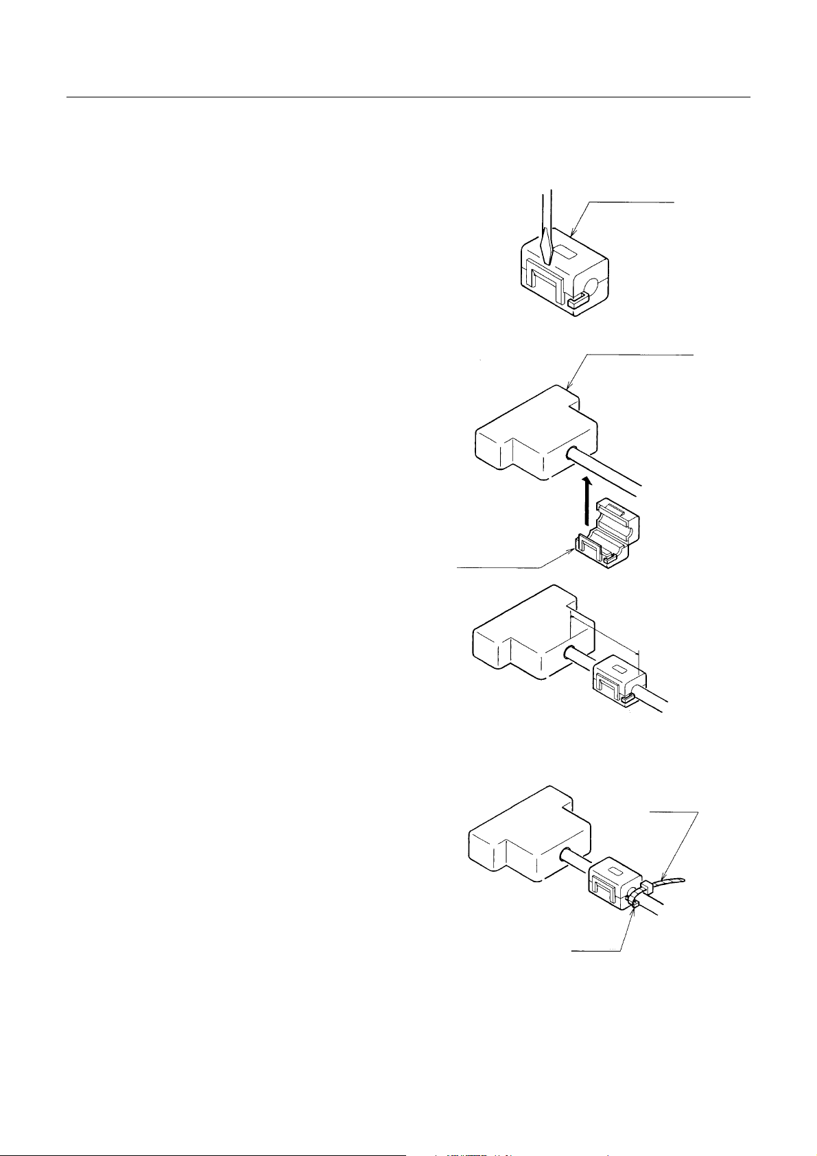
4.3 Attaching the Ferrite Core to the Interface Cable
iDP3420/3421/3423 User’s Manual
1. Turn off the power.(Mating side included)
2. With a regular screwdriver, unlatchand open the
ferrite core.
3. Attach the ferrite core to the interface cable so
that its end face will be within up to 5 cm.
Ferrite Core
Interface Cable
Ferrite Core
4. Secure the arm of the ferrite core onto the cable
with a fastener so that the ferrite core will not
move. Cut off the surplus part of the fastener.
Within 5 cm
Fastener
Arm
10 CITIZEN
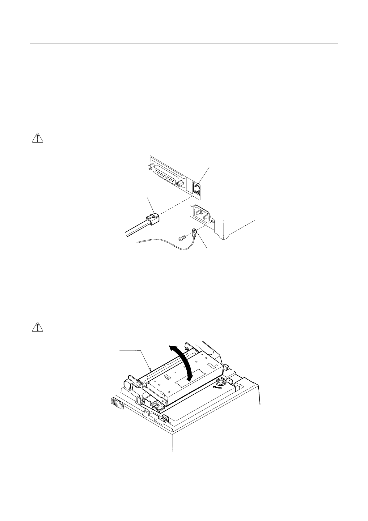
4.4 Connecting the Drawer Kick-Out Connector
1. Turn off the power.
2. Check the top and bottom of the drawer kick-out cable connector and connect it to the drawer kick-out
connector located on the back of the printer.
3. Screw the grounding cable of the drawer to the grounding terminal of the printer.
iDP3420/3421/3423 User’s Manual
CAUTION: •
• Connec t only the prescribeddrawer (Solenoid) to the drawer kick-out connector.
••
Drawer Kick-Out Cable Connector
4.5 Opening/Closing the Auto Cutter (iDP3421/3423)
The auto cutter is secured by a magnet. Hold the auto cutter and turn it i n the arrow -i ndicated direction to
open/close it.
Drawer Kick-Out Connector
Earth Terminal
CAUTION: •
• When closing the auto cutter, do so gently not to give a shock.
••
Auto Cutter
11 CITIZEN
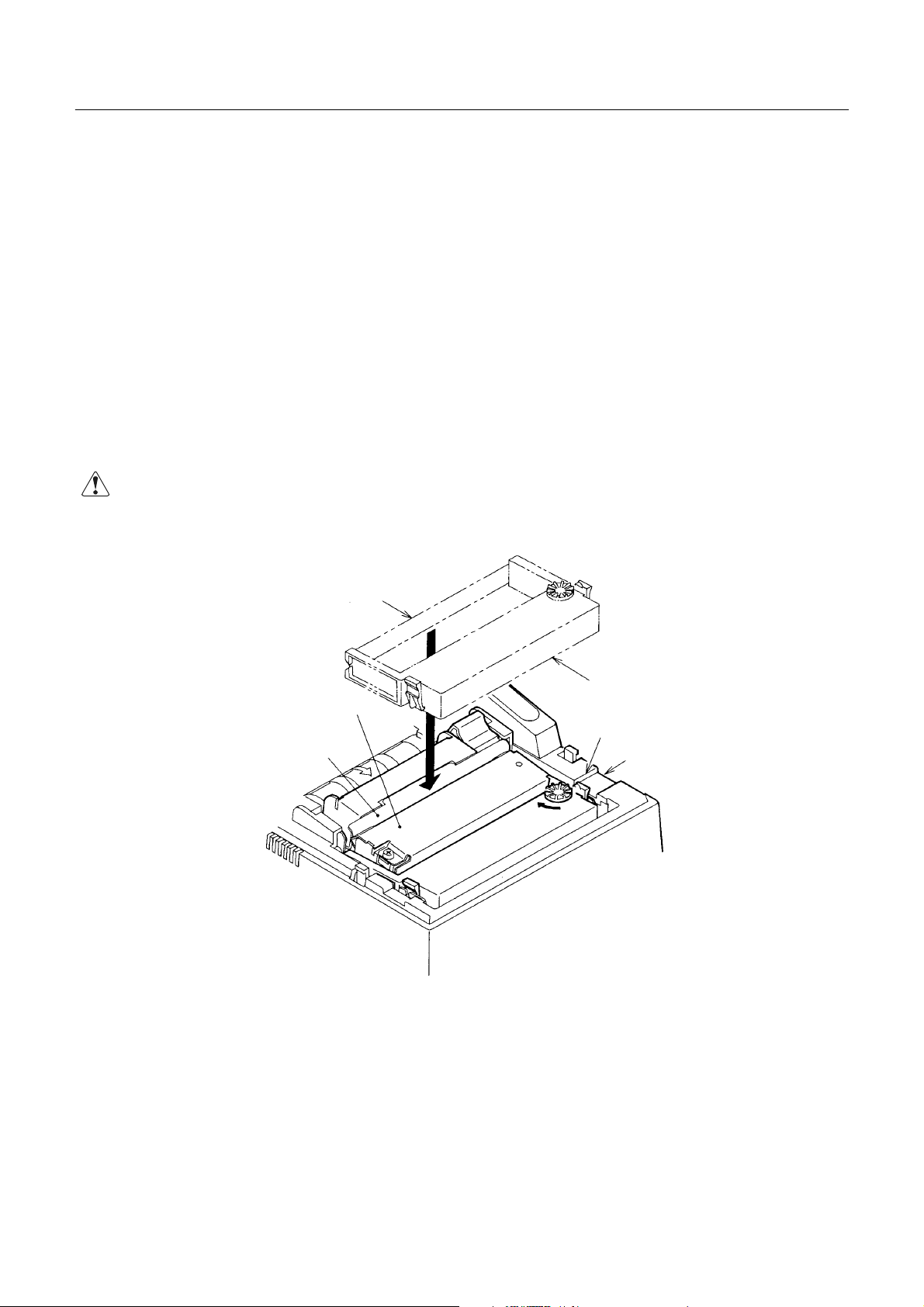
4.6 Setting the Cassette Ribbon
(1) Open the printer cover.
(2)Openthe auto cutter. (iDP3421/3423)
(3)If the ribbon is slackened, turn the knob in the arrow-indicated direction to give the tension to it before
setting.
(4)While putting the ribbon in between the head cover and platen, push the locking claws into the holder of
the printer.
(5) Turn the knob of the cassette ribbon in the arrow -indicated direction to eliminate slackness of the ribbon.
(6) Toremove the cassette ribbon, lift it while tilting the locking claws onbothsides toward the inside.
(7)Close the auto cutte r. (iDP3421/3423)
iDP3420/3421/3423 User’s Manual
CAUTION: •
• When closing the auto cutter, do so gently not to give a shock.
••
Ribbon
Cassette Ribbon
Head Cover
Knob
Platen
Locking Claw
12 CITIZEN
4.7 Inserting the Paper
4.7.1 Inserting the Paper (iDP3420/3421)
(1) Put your hands in the concave parts on both sides of the printer cover, and open it until it comes to a
stop.
(2) Cut the end of the paper roll at close to a right angle.
CAUTION : • Be sure to use the specifiedpaper roll.
• Use of unspecifie dpapermay adversely affect print quality, printer service life, and so on.
• The printer cover is not detachable. Do not apply an excessive force beyond its
stopping position.
• Do not insert a frayed or bent end of paper into the printer.
iDP3420/3421/3423 User’s Manual
(3) Checkthe winding directionofthe paper roll.
(4) Opening the paper holder, support the center of the paper roll corre ctly.
(5) Turnon the printer.
(6) Insert theend of the paper roll straight into the paper inlet slot (Indicated by an arrow on the case).
(7) The paper is automatically fed in and comes out the paper outlet of the printer (Paper outlet of the
auto cutter for the iDP3421).
(8) iDP3420: Put the paper into the paper outlet of the printer cover, close the cover, and cut the
surplus paper by the tear bar.
iDP3421: Cut the surplus paper by the tear bar at the paper outlet of the auto cutter and close the
printer cover.
CAUTION : • If the paper is slack, rewind it, to remo v e the slack.
• If the paper is set slantwise, operate the paper-free lever, to correct the paper position.
• While printing, do not hold the paper. This ca n cause a paper jam.
• When closing the auto cutter, do so gently not to give a shock.
13 CITIZEN

Paper Roll Setting Direction
iDP3420/3421/3423 User’s Manual
14 CITIZEN
 Loading...