


LINE THERMAL PRINTER
MODEL iDP3240
User’s Manual

WEEE MARK
,I\RXZDQWWRGLVSRVHWKLVSURGXFWGRQRWPL[ZLWKJHQHUDOKRXVHKROGZDVWH7KHUHLVD
En
VHSDUDWHFROOHFWLRQV\VWHPVIRUXVHGHOHFWURQLFVSURGXFWVLQDFFRUGDQFHZLWKOHJLVODWLRQXQGHU
WKH:((('LUHFWLYH'LUHFWLYH(&DQGLVHIIHFWLYHRQO\ZLWKLQ(XURSHDQ8QLRQ
:HQQ6LHGLHVHV3URGXNWHQWVRUJHQZROOHQGDQQWXQ6LHGLHVELWWHQLFKW]XVDPPHQPLWGHP
Ge
+DXVKDOWVPOO(VJLEWLP5DKPHQGHU:((('LUHNWLYHLQQHUKDOEGHU(XURSlLVFKHQ8QLRQ
'LUHNWLYH(&JHVHW]OLFKH%HVWLPPXQJHQIUVHSDUDWH6DPPHOV\VWHPHIUJHEUDXFKWH
HOHNWURQLVFKH*HUlWHXQG3URGXNWH
6LYRXVVRXKDLWH]YRXVGpEDUUDVVHUGHFHWDSSDUHLOQHOHPHWWH]SDVjODSRXEHOOHDYHFYRV
Fr
RUGXUHVPpQDJqUHV,OH[LVWHXQV\VWqPHGHUpFXSpUDWLRQGLVWLQFWSRXUOHVYLHX[DSSDUHLOV
pOHFWURQLTXHVFRQIRUPpPHQW jODOpJLVODWLRQ :(((VXU OHUHF\FODJHGHV GpFKHWVGHV
pTXLSHPHQWVpOHFWULTXHVHWpOHFWURQLTXHV'LUHFWLYH(&TXLHVWXQLTXHPHQWYDODEOH
GDQVOHVSD\VGHO¶8QLRQHXURSpHQQH
/HVDSSDUHLOVHWOHVPDFKLQHVpOHFWULTXHVHWpOHFWURQLTXHVFRQWLHQQHQWVRXYHQWGHVPDWLqUHV
GDQJHUHXVHVSRXUO¶KRPPHHWO¶HQYLURQQHPHQWVLYRXVOHVXWLOLVH]HWYRXVYRXVHQGpEDUUDVVH]
GHIDoRQLQDSSURSULpH
6LGHVHDGHVKDFHUVHGHHVWHSURGXFWRQRORPH]FOHFRQUHVLGXRV GRPpVWLFRVGHFDUiFWHU
Sp
JHQHUDO([LVWHXQVLVWHPDGHUHFRJLGDVHOHFWLYDGHDSDUDWRVHOHFWUyQLFRVXVDGRVVHJ~Q
HVWDEOHFHODOHJLVODFLyQSUHYLVWDSRUOD'LUHFWLYD&(VREUHUHVLGXRVGHDSDUDWRV
HOpFWULFRV\HOHFWUyQLFRV5$((YLJHQWH~QLFDPHQWHHQOD8QLyQ(XURSHD
6HGHVLGHUDWHJHWWDUHYLDTXHVWRSURGRWWRQRQPHVFRODWHORDLULILXWLJHQHULFLGLFDVD(VLVWH
It
XQVLVWHPDGLUDFFROWDVHSDUDWRSHULSURGRWWLHOHWWURQLFLXVDWLLQFRQIRUPLWjDOODOHJLVOD]LRQH
5$(('LUHWWLYD&(YDOLGDVRORDOO¶LQWHUQRGHOO¶8QLRQH(XURSHD
'HSRQHHUGLWSURGXFWQLHWELMKHWJHZRQHKXLVKRXGHOLMNDIYDOZDQQHHUXKHWZLOWYHUZLMGHUHQ(U
Du
EHVWDDWLQJHYROJHGH:(((ULFKWOLMQ5LFKWOLMQ(*HHQVSHFLDDOZHWWHOLMN
YRRUJHVFKUHYHQYHU]DPHOV\VWHHPYRRUJHEUXLNWHHOHNWURQLVFKHSURGXFWHQZHONDOOHHQJHOGW
ELQQHQGH(XURSHVH8QLH
+YLVGXYLOVNLOOHGLJDIPHGGHWWHSURGXNWPnGXLNNHVPLGHGHWXGVDPPHQPHGGLWDOPLQGHOLJH
Da
KXVKROGQLQJVDIIDOG'HUILQGHVHWVHSDUDWLQGVDPOLQJVV\VWHPIRUXGWMHQWHHOHNWURQLVNHSURGXNWHU
LRYHUHQVVWHPPHOVHPHGORYJLYQLQJHQXQGHU:(((GLUHNWLYHWGLUHNWLY(&VRP
NXQHUJOGHQGHLGHQ(XURSLVNH8QLRQ
6HTXLVHUGHLWDUIRUDHVWHSURGXWRQmRRPLVWXUHFRPROL[RFRPXP'HDFRUGRFRPDOHJLVODomR
Por
TXHGHFRUUHGD'LUHFWLYD5(((±5HVtGXRVGH(TXLSDPHQWRV(OpFWULFRVH(OHFWUyQLFRV
&(H[LVWHXPVLVWHPDGHUHFROKDVHSDUDGRSDUDRVHTXLSDPHQWRVHOHFWUyQLFRVIRUDGH
XVRHPYLJRUDSHQDVQD8QLmR(XURSHLD
-HĪHOL]DPLHU]DV]SR]E\üVLĊWHJRSURGXNWXQLHZ\U]XFDMJRUD]HP]H]Z\Ná\PL
Pol
GRPRZ\PLRGSDGNDPL:HGáXJG\UHNW\Z\:((('\UHNW\ZD(&
RERZLą]XMąFHMZ8QLL(XURSHMVNLHMGODXĪ\ZDQ\FKSURGXNWyZHOHNWURQLF]Q\FK
QDOHĪ\VWRVRZDüRGG]LHOQHVSRVRE\XW\OL]DFML

Declaration of Conformity
This printer conforms to the following Standards:
Low Voltage Directive 73/23/EEC, 93/68/EEC and the EMC Directive 89/336/EEC,
92/31/EEC, 93/68/EEC.
LVD : EN60950
EMC : EN55022 Class A
EN61000-3-2
EN61000-3-3
EN55024
This declaration is applied only for 230V model.
WARNING : This is a Class A product. In a domestic environment this product may cause radio
interference in which case the user may be required to take adequate measures.
CITIZEN is registered trade mark of CITIZEN WATCH CO., LTD., Japan
CITIZEN es una marca registrada de CITIZEN WATCH CO., LTD., Japón
Windows codepage is a registered trademark of Microsoft Corporation
— i —

IMPORTANT SAFETY INSTRUCTIONS
• Read all of these instructions and save them for future reference.
• Follow all warnings and instructions marked on the product.
• Unplug this product from the wall outlet before cleaning. Do not use liquid or aerosol
cleaners. Use a damp cloth for cleaning.
• Do not use this product near water.
• Do not place this product on an unstable cart, stand or table. The product may fall,
causing serious damage to the product.
• Slots and openings on the back or bottom of the case are provided for ventilation. To
ensure reliable operation of the product and to protect it from overheating, do not
block or cover these openings. The openings should never be blocked by placing the
product on a bed, sofa, rug or other similar surface. This product should never be
placed near or over a radiator or heater. This product should not be placed in an builtin installation unless proper ventilation is provided.
• This product should be operated from the type of power source indicated on the
marking label. If you are not sure of the type of power available, consult your CITIZEN
SYSTEMS dealer or local power company.
• Do not allow anything to rest on the power cord. Do not place this product where the
cord will be walked on.
• If an extension cord is used with this product, make sure that the total of the ampere
ratings of the products plugged into the extension cord does not exceed the extension
cord ampere rating. Also, make sure that the total of all products plugged into the wall
outlet does not exceed 15 amperes.
• Never push objects of any kind into this product through cabinet slots as they may
touch dangerous voltage points or short out parts that could result in a risk of fire or
electric shock. Never spill liquid of any kind on the product.
• Except as explained elsewhere in this manual, do not attempt to service this product
by yourself. Opening and removing the covers that are marked “Do Not Remove” may
expose you to dangerous voltage points or other risks. Refer all servicing on those
components to service personnel.
• Unplug this product from the wall outlet and refer servicing to qualified service
personnel under the following conditions:
A. When the power cord or plug is damaged or frayed.
B. If liquid has been spilled into the product.
C. If the product has been exposed to rain or water.
D. If the product does not operate normally when the operating instructions are
followed. Adjust only those controls that are covered by the operating instructions
since improper adjustment of other controls may result in damage and will often
require extensive work by a qualified technician to restore the product to normal
operation.
E. If the product has been dropped or the cabinet has been damaged.
F. If the product exhibits a distinct change in performance, indicating a need for
service.
• Please keep the poly bag which this equipment is packed in away from children or
throw it away to prevent children from putting it on. Putting it on may cause
suffocation.
— ii —

WICHTIGE SICHERHEITSANWEISUNGEN
• Lesen Sie die nachfolgenden Anweisungen sorgfältig durch und bewahren Sie sie auf.
• Befolgen Sie alle auf dem Drucker vermerkten Hinweise und Anweisungen. Vor dem
Reinigen grundsätzlich Stecker aus der Steckdose ziehen. Keine Flüssigkeiten oder
Aerosolreiniger benutzen. Nut mit einem feuchten Tuch abwischen.
• Der Drucker darf nicht in der Nähe von Wasser aufgestellt werden.
• Drucker nicht auf einem unstabilen Wagen, Stand oder Tisch aufstellen. Der Drucker
könnte herunterfallen und dabel beschädigt werden.
• Schlitze und Öffnungen im Gehäuse, in der Rückwand und im Boden dienen der
Belüftung. Sie dürfen keinesfalls zugedeckt oder blockiert werden, da sich der Drucker
sonst überhitzt. Drucker nicht auf ein Bett, Sofa, Teppich oder dergleichen stellen.
Drucker nicht in der Nähe eines Heizkörpers aufstellen. Drucker darf nicht eingebaut
werden, falls nicht für ausreichende Belüftung gesorgt ist.
• Drucker nur mit der auf dem Typschild angegebenen Spannung betreiben. Wenn Sie
sich nicht sicher sind, fragen Sie ihren Händler oder ihr zuständiges Elektrizitätswerk.
• Nichts auf das Stromanschlußkabel stellen. Kabel muß so verlegt werden, daß man
nicht darauftreten kann.
• Ein etwaiges Verlängerungskabel muß der Stromstärke aller daran angeschlossenen
Geräte entsprechen.
• Keine Gegenstände in die Gehäuseschlitze schieben.
• Drucker darf nur da gewartet werden, wo im Handbuch angegeben, Öffnen und.
Abnehmen von Abdeckungen, die mit “Do not remove” gekennzeichenet sind, könnte
gefährliche spannungführende Stellen oder sonstige Gefahrenpunkte freilegen. Die
Wartung solcher Stellen darf grundsätzlich nur von besonders ausgebildetem
Fachpersonal vorgenommen werden.
A. Wenn das Stromanschlußkabel oder der Stecker beschädigt oder durch-gescheuert
ist.
B. Wenn Flüssigkeit auf dem Drucker verschüttet wurde.
C. Wenn der Drucker im Regen gestanden hat oder Wasser darauf verschüttet wurde.
D. Wenn der Drucker trotz genauer Befolgung der Betriebsvorschriften nicht richtig
arbeitet. Nur die in der Bedienungsanleitung angegebenen Einstellungen
vornehmen. Ein Verstellen anderer Bedienungselemente könnte den Drucker
beschädigen und macht umständliche Arbeiten eines qualifizierten Technikers
erforderlich, um den Drucker Wieder auf den normalen Betrieb einzustellen.
E. Wenn der Drucker heruntergefallen ist oder das Gehäuse beschädigt wurde.
F. Wenn der Drucker in seiner Leistung nachläßt.
• Bitte halten Sie den Kunststoffbeutel, in den die Ware verpackt ist, von Kindern entfernt,
oder werfen Sie ihn weg, damit er nicht in die Hande von Kindern gerät. Das
Überstülpen des Beutels kann zum Ersticken führen.
Lärmemission kleiner 70dBA
— iii —

IMPORTANT: This equipment generates, uses, and can radiate radio frequency
energy and if not installed and used in accordance with the instruction manual,
may cause interference to radio communications. It has been tested and found to
comply with the limits for a Class A computing device pursuant to Subpart J of
Part 15 of FCC Rules, which are designed to provide reasonable protection against
such interference when operated in a commercial environment. Operation of this
equipment in a residential area is likely to cause interference, in which case the
user at his own expense will be required to take whatever measures may be
necessary to correct the interference.
CAUTION: Use shielded cable for this equipment.
Sicherheitshinweis
Die Steckdose zum Anschluß dieses Druckers muß nahe dem Grät angebracht und
leicht zugänglich sein.
For Uses in Canada
This digital apparatus does not exceed the class A limits for radio noise emissions
from digital apparatus, as set out in the radio interference regulations of the
Canadian department of communications.
Pour L’utilisateurs Canadiens
Cet appareil numérique ne dépasse pas les limites de carégorie a pour les
émissions de bruit radio émanant d’appareils numériques, tel que prévu dans les
réglements sur l’interférence radio du départment Canadien des communications.
— iv —

GENERAL PRECAUTIONS
• Prior to using the iDP3240 Printer, be sure to read this User’s Manual thoroughly.
Please keep it handy so that you can refer to it whenever necessary.
• The information contained herein may be changed without prior notice.
• Reproduction of part or all of the User’s Manual without permission is strictly
prohibited.
• Never service, disassemble, or repair parts that are not described in the User’s
Manual.
• Note that CITIZEN SYSTEMS shall not be responsible for any damages
attributable to incorrect operation/handling or improper operation environments,
which are not specified in the User’s Manual.
• Operate this printer only in the manners as described in the User’s Manual;
otherwise, accidents or problems could possibly occur.
• Data are basically temporary; they cannot be stored or saved for a long time or
permanently. Please note that CITIZEN SYSTEMS shall not be responsible for any
damages or lost profits resulting from the loss of data attributable to accidents,
repairs, tests, and so on.
• If you have any questions, or notice any clerical errors or omissions regarding the
information in the User’s Manual, please contact your CITIZEN SYSTEMS dealer.
• Please note that CITIZEN SYSTEMS shall not be responsible for any results or
effects resulting from operation of this Printer even if the information in the
User’s Manual is properly observed.
— v —
SAFETY PRECAUTIONS
In order to help prevent safety hazards to operators or any other persons and
damages to property, special warning symbols are used in this User’s Manual to
indicate important items to be strictly observed.
• The following describes the degrees of hazards and damages that can occur if the
iDP3240 Printer is incorrectly operated without observing the instructions
indicated by the warning symbols.
— WHICH SHOULD BE STRICTLY OBSERVED
WARNING
Negligence of the precautions indicated by this symbol may result in death or
serious injuries.
CAUTION
Negligence of the precautions indicated by this symbol may result in injuries or
damages to property.
This is a symbol mark used to alert your attention to important items.
This is a symbol mark used to indicate useful information, such as
i
procedures, instruction or the like.
— vi —
WARNING
● Never handle the iDP3240 Printer in the manners descried below; otherwise, it
may be damaged, get out of order or overheated, possibly causing smoke, fire
or electric shock. If the printer is damaged or breaks down, be sure to turn off
the power, disconnect the power plug from the wall outlet, and contact your
CITIZEN SYSTEMS dealer.
• Do not allow the printer to be subjected to any strong impact or shock, such as
stamping, hitting, dropping, and the like.
• Install the printer in a well-ventilated place. Do not use the printer in such a
manner that its ventilation slots are blocked.
• Do not install the printer in a place like a laboratory where chemical reactions
are expected, or in a place where saltish gases are present in the atmosphere.
• Use the printer only on the specified voltage and frequency.
• Do not connect/disconnect the power cord or data cable by holding the cable.
• Do not pull or carry the printer in such a manner that undesirable force is
applied to the cables.
• Do not drop or insert any foreign substances, such as paper clips or pins, into
the printer.
• Do not spill any liquid on or spray any chemical-containing liquid over the
printer. If any liquid is spilled on the printer, turn it off, disconnect the power
cord from the wall outlet, and contact your CITIZEN SYSTEMS dealer.
• Do not connect the printer to an electrical outlet shared by other devices.
• Do not disassemble or modify the printer in any manner; otherwise, a fire or
electric shock may result.
• Should water enter the equipment by any chance, unplug it and contact your
CITIZEN SYSTEMS dealer. Using it in that condition may result in fire or
electric shock.
• Do not damage, break, alter, twist excessively, pull, or bundle the power cord.
Avoid placing heavy objects on, or heating the power cord, as this may lead to
damages to the power supply which may cause a fire, an electric shock, or a
malfunction. Contact your CITIZEN SYSTEMS dealer if the power cord is
damaged.
• Do not overload a single electrical outlet by using a table tap or a current tap
socket from it. This may result in fire or electric shock.
●
The plastic bag the printer came in must be disposed of properly or kept away
from children. Wearing it over the head may lead to suffocation.
— vii —

PRECAUTIONS FOR INSTALLATION
• Do not use or store the iDP3240 Printer in a place exposed to heat of fire, moisture
or direct sunlight, or in a place where the prescribed operating temperature and
humidity are not met, or in a place exposed to oily mist, iron powder or dust;
otherwise, the printer may get out of order, emit smoke or catch fire.
• Do not install the printer in a place like a laboratory where chemical reactions are
expected, or in a place where saltish gases are present in the atmosphere;
otherwise, there may occur a danger of fire or electric shock.
• Install the printer on a horizontal, sturdy table in a place provided with proper
ventilation and free from any vibration. (Be careful not to block the ventilation slots
of the printer.)
• Do not put any object on the printer, or this may cause a trouble.
• Do not use the printer near a radio or television receiver. Avoid sharing an electrical
outlet with a radio or television receiver, or this may cause a reception problem.
• Use the printer only on the specified voltage and frequency; otherwise it may emit
smoke, catch fire or cause other problems.
• Confirm that the wall outlet used for printer connection has sufficient electrical
capacity.
• Avoid sharing a single electrical outlet with other devices; otherwise, the electrical
capacity may be exceeded, causing the outlet to overheat or the power supply to be
shut down. Also, do not stamp or put any object on the cables.
• Never connect the grounding cable to a gas pipe, or this may lead to a danger of
explosion. Before connecting or disconnecting the grounding cable, be sure to
disconnect the power plug from the wall outlet.
• Be sure to turn off the power of the printer and the host computer connected before
connecting or disconnecting the cables; always hold both plug and cable. Do not
pull or carry the printer in such a manner that an undesirable load is applied to the
cables.
• Connect the connector cables correctly and securely. Especially, if a connection is
made with the polarity reversed, internal elements inside the printer may be
damaged or the host computer connected may be adversely affected.
• Use shielding wires or twist paired wires for signal lines in order to minimize the
effects from noise. Avoid connecting to a device that is likely to generate much
noise.
• When a drawer Kick-Out Connector is provided, do not connect it to any other
device than solenoids with prescribed specifications, or this could cause trouble.
• Install and use the printer in a place provided with a suitable wall outlet nearby so
that you can immediately disconnect the power plug to shut off the power to the
printer if an abnormal condition occurs.
• When the equipment will not be used for a long period of time, unplug it.
• When transporting the equipment, remove the paper roll from it.
— viii —
PRECAUTIONS FOR HANDLING
Observe the following precautions to use the iDP3240 Printer correctly and avoid
troubles from occurring.
• Do not use any other power supply than the specified AC adapter.
• Do not allow the printer to start printing when there is no recording paper
installed.
• Be careful not to drop foreign substances, such as paper clips, pins or screws,
into the printer.
• Do not spill any liquid on the printer, or spray it with any chemical-containing
liquid.
• Do not stamp on, drop, hit, or impart any strong shock to the printer.
• Never use any pointed object such as a pen, to operate the controls on the
operation panel.
• Do not use cellophane tape to join the ends of paper to allow continuous printing.
• Never pull the end of the paper installed forcibly with the printer cover left closed.
• When opening/ closing the cover, be careful that the paper does not get caught.
To prevent injuries and associated damages:
• Do not touch the printing part of the print head.
• While the printer is turned on, never touch the moving parts inside, such as the
cutter, gears, and electrical parts.
• Be careful to avoid bodily injuries or damaging other objects with edges of sheet
metal parts.
• Should any abnormal condition occur while the printer is operating, stop it
immediately and disconnect the power plug from the wall outlet.
• When opening/closing the cover, and so on, be careful not to catch your hand or
finger on the equipment.
• Refer all necessary corrective actions to your CITIZEN SYSTEMS dealer (See “9.
MAINTENANCE AND SERVICE” on Page 41.) Do not try to disassemble and repair
the printer on your own.
— ix —
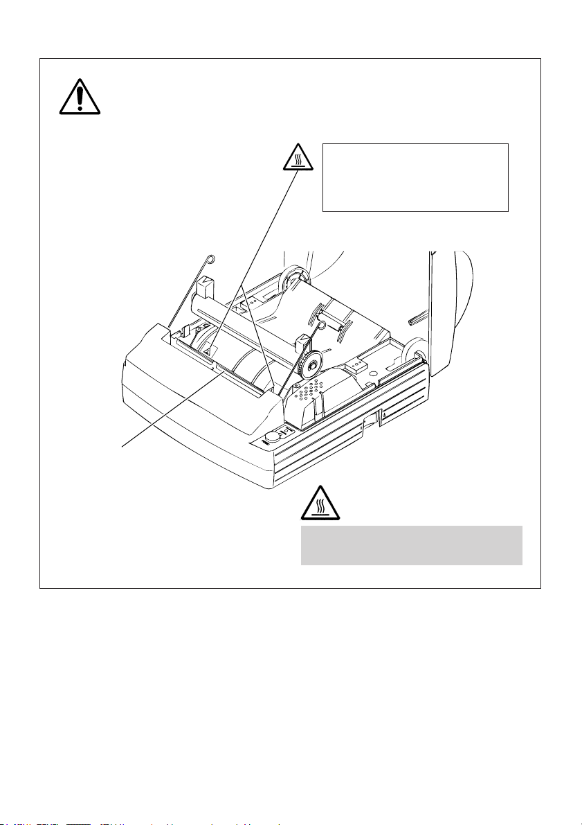
In the position indicated below, a label is provided to alert your attention.
Read the cautionary information on it, and handle the printer properly.
This label alerts you to the
print head as it becames HOT,
and if you touch it, you may
get burnt.
Print head
HOT AREA:
Be careful not to touch this area to
avoid burns as it becomes HOT.
— x —
i
DAILY MAINTENANCE
• Prior to start maintenance work, be sure to turn off the printer.
• When cleaning the platen, use a cotton swab applied with ethyl alcohol and wipe
off stains.
Platen
CAUTION:
Avoid cleaning the print head immediately after printing is finished. The print
head is HOT.
• Use a dry soft cloth to wipe off stains and dust from the surfaces of the printer
covers.
• When wiping clean heavily stained areas, use a cloth which should be dipped in
water and then wrung strongly. Never use organic solvents, such as alcohol,
thinner, trichlene, benzene, ketone, or chemical dusters.
• If the printer is contaminated with paper dust, use a soft brush to wipe off.
— xi —
DAILY MAINTENANCE
i
Cleaning the print head
1 Turn off the power of the printer.
2 Remove the platen roller unit. Refer to “4.6 Removing paper Jams”.
3 Using a gauze impregnated with a small amount of alcohol, wipe off stains and
dust on the heat-emitting surface of the head.
4 Replace the platen roller unit.
Print head
CAUTION:
Avoid cleaning the print head immediately after printing is finished. The print
head is HOT. Do not touch the heat-emitting surface of the head with bare
hands or metal objects.
— xii —

THE TABLE OF CONTENTS
1. GENERAL OUTLINE ................................................................... 1
1.1 Features ..................................................................................................... 1
1.2 Unpacking ..................................................................................................2
1.3 Before using the printer ............................................................................ 3
2. BASIC SPECIFICATIONS ............................................................ 4
2.1 Model Classification .................................................................................. 4
2.2 Basic Specifications .................................................................................. 5
2.3 Print Paper Specifications ........................................................................ 6
2.3.1 Recommended Paper ....................................................................... 6
2.3.2 Print Position and Barcode Printing ................................................ 7
2.3.3 Cutter Position ...................................................................................8
3. OUTER APPEARANCE AND COMPONENT PARTS.................. 9
3.1 iDP3240 ...................................................................................................... 9
4. OPERATION .............................................................................. 10
4.1 Connecting the AC Adapter and AC Power Cord ................................. 10
4.2 Connecting Interface Cables .................................................................. 11
4.3 Connecting the Drawer Kick-Out Connector .........................................12
4.4 Setting / Replacing Paper Rolls ..............................................................13
4.4.1 Setting Paper Rolls.......................................................................... 13
4.4.2 Setting Paper Rolls when Easy Loading is Disabled .................... 16
4.5 Removing the Remainder of Paper Rolls ..............................................17
4.6 Removing Paper Jams............................................................................ 18
4.7 Releasing a Locked Cutter ......................................................................19
4.8 Cleaning the Print Head .......................................................................... 20
4.9 Operation Panel and Error Indication .................................................... 21
4.10 Self Printing ...........................................................................................23
4.11 Hexadecimal Dump............................................................................... 24
5. SETTING DIP SWITCHES ......................................................... 25
5.1 Location of DIP Switches ........................................................................ 25
5.2 Table for Setting DIP Switches ............................................................... 26
— xiii —

6. PARALLEL INTERFACE............................................................. 29
6.1 Bidirectional Parallel Interface (IEEE1284) ............................................ 29
6.1.1 Compatibility Mode (Host → Printer communication :
Centronics compliant) .................................................................... 29
6.1.2 Reverse Mode (Printer → Host communication) .......................... 29
6.1.3 Connector Pin Configuration.......................................................... 30
6.2 Description of Input and Output Signals ............................................... 31
6.2.1 Input and Output Signals ............................................................... 31
6.2.2 Electrical Characteristics................................................................. 32
6.2.3 Timing Chart (Compatibility Mode) .............................................. 33
6.2.4 Data Reception Control................................................................... 33
6.2.5 Buffering .......................................................................................... 33
7. SERIAL INTERFACE .................................................................. 34
7.1 Specifications .......................................................................................... 34
7.2 Connector Pin Configuration .................................................................. 35
7.3 Description of Input and Output Signals ............................................... 36
7.3.1 Input and Output Signals ............................................................... 36
7.3.2 Error Detection ................................................................................ 37
7.3.3 Data Reception Control................................................................... 37
7.3.4 Buffering .......................................................................................... 37
7.3.5 Electrical Characteristics................................................................. 38
8. DRAWER KICK-OUT CONNECTOR AND POWER CONNECTOR...
8.1 Specifications of Drawer Kick-Out Connector ...................................... 39
8.1.1 Drawer Kick-Out drive signal ......................................................... 39
8.1.2 Electrical characteristics ................................................................. 39
8.1.3 Connector Pin Configuration.......................................................... 39
8.1.4 Drive Circuit .....................................................................................40
8.2 Specifications of the Power Connector .................................................40
39
9. MAINTENANCE AND SERVICE ............................................... 41
— xiv —

10. PRINT CONTROL FUNCTIONS .............................................. 42
10.1 Command List ....................................................................................... 42
10.2 Command Details ..................................................................................45
10.2.1 Description of Each Item .............................................................. 45
10.2.2 Command Details.......................................................................... 46
11. CHARACTER CODES TABLE................................................ 141
11.1 Code page ............................................................................................ 141
11.1.1
11.1.2 Codepage Katakana (Japanese)................................................. 142
11.1.3 Codepage PC850 (Multilingual) ................................................. 143
11.1.4 Codepage PC860 (Portuguese) .................................................. 144
11.1.5 Codepage PC863 (Canadian-French) .........................................145
11.1.6 Codepage PC865 (Nordic) .......................................................... 146
11.1.7 Codepage PC852 (Eastern Europe) ............................................ 147
11.1.8 Codepage PC866 (Russian) ........................................................ 148
11.1.9 Codepage PC857 (Turkish) ......................................................... 149
11.1.10 Windows Codepage .................................................................. 150
11.2 International Character Codes Table ................................................. 151
Codepage 00H to 7FH & PC437 (USA, European Standard) ........
141
12. APPENDIX 1. PAGE MODE .................................................. 152
12.1 Overview .............................................................................................. 152
12.2 Mapping of print data in the print area .............................................153
12.2.1 Example of the Use of PAGE MODE .......................................... 155
13. APPENDIX 2. BIDIRECTIONAL PARALLEL INTERFACE ........ 158
13.1 Overview .............................................................................................. 158
13.1.1 Parallel Interface Communication Modes ................................. 158
13.1.2 Interfacing Phases ....................................................................... 159
13.2 Negotiation .......................................................................................... 160
13.2.1 Overview ...................................................................................... 160
13.2.2 Negotiation Procedure................................................................ 160
13.2.3 Precautions ..................................................................................161
13.2.4 Data Communication from Printer to Host ............................... 162
13.2.4.1 Nibble Mode ........................................................................162
13.2.4.2 Byte Mode............................................................................ 163
13.2.5 Device ID ......................................................................................164
13.2.6 Termination.................................................................................. 164
— xv —

14. APPENDIX 3. IDENTIFICATION OF SEND STATUS............... 166
15. APPENDIX 4. OUTLINE DRAWING...................................... 167
15.1 iDP3240 ................................................................................................ 167
15.2 AC Adapter (31AD) .............................................................................. 168
16. APPENDIX 5. BLOCK DIAGRAM.......................................... 169
— xvi —

<<<
German
>>>
INHALT
4. BETRIEB .................................................................................. 179
4.1 Anschließen des Netzteils und Netzkabels ......................................... 179
4.2 Anschließen der Schnittstellenkabel ...................................................180
4.3 Anschließen des Drawer Kickout-Steckers ......................................... 181
4.4 Einlegen / Auswechseln von Papierrollen........................................... 182
4.4.1 Einlegen von Papierrollen ............................................................ 182
4.4.2 Einlegen von Papierrollen bei deaktiviertem
einfachen Ladevorgang ................................................................ 185
4.5 Entfernen von Papierrollenresten ........................................................ 186
4.6 Beseitigen von Papierstaus ..................................................................187
4.7 Freigeben eines verriegelten Papierschneiders ................................. 188
4.8 Reinigen des Druckkopfes ....................................................................189
4.9 Bedienungsfeld und Fehleranzeige ..................................................... 190
4.10 Drucktest ..............................................................................................192
4.11 Hexdump ............................................................................................. 193
5. EINSTELLEN DER DIP-SCHALTER......................................... 194
5.1 Position der DIP-Schalter...................................................................... 194
5.2 DIP-Schaltertabelle................................................................................ 195
6. PARALLELE SCHNITTSTELLE................................................ 198
6.1 Bidirektionale parallele Schnittstelle (IEEE1284) ................................198
6.1.1 Kompatibilitätsmodus (Host → Druckerkommunikation:
Centronics-kompatibel) ................................................................ 198
6.1.2 Reverse-Modus (Drucker → Hostkommunikation) ..................... 198
6.1.3 Belegung der Anschlußstifte........................................................ 199
6.2 Beschreibung von Eingangs- und Ausgangssignalen ....................... 200
6.2.1 Eingangs- und Ausgangssignale ................................................. 200
6.2.2 Elektrische Kenndaten .................................................................. 201
6.2.3 Timing-Tabelle (KompatibilitätsModus) ...................................... 202
6.2.4 Datenempfangssteuerung ............................................................ 202
6.2.5 Datenpufferspeicher ..................................................................... 202
— xvii —

7. SERIELLE SCHNITTSTELLE ................................................... 203
7.1 Technische Daten ..................................................................................203
7.2 Belegung der Anschlußstifte ................................................................ 204
7.3 Beschreibung der Eingangs- und Ausgangssignale .......................... 205
7.3.1 Eingangs- und Ausgangssignale ................................................. 205
7.3.2 Fehlererkennung ........................................................................... 206
7.3.3 Datenempfangssteuerung ............................................................ 206
7.3.4 Pufferung ....................................................................................... 206
7.3.5 Elektrische Kenndaten .................................................................. 207
8.
DRAWER KICKOUT- ANSCHLUSS UND STROMANSCHLUSS .....
8.1 Technische Daten des Drawer KickOut-Anschlusses ......................... 208
8.1.1 Drawer KickOut-Treibersignal ......................................................208
8.1.2 Elektrische Kenndaten .................................................................. 208
8.1.3 Belegung der Anschlußstifte........................................................ 208
8.1.4 Treiberschaltung ........................................................................... 209
8.2 Technische Daten des Stromanschlusses ...........................................209
208
9. WARTUNG UND KUNDENDIENST ....................................... 210
— xviii —

1. GENERAL OUTLINE
The iDP3240 is a compact-sized, line thermal printer developed for a variety of
applications. It has abundant built-in features, and can be used as a data
communication terminal, pos terminal, kitchen terminal and for other applications.
1.1 Features
• Compactness and lightweight with a small footprint.
• Low-cost design accomplished by using as small a component count as possible.
• Simple paper setting - All you have to do is just drop in a paper roll and closing
the cover.
• Removable platen structure, which makes paper handling, head cleaning, and
maintenance easy.
• Line thermal printing, which allows high-speed, low-noise operation.
• Registration of user-defined characters and logos into flash memory.
• Built-in input buffer.
• Bar-code printing (Possible using special commands).
• Built-in Drawer Kick-Out interface.
• Auto cutter mechanism provided as a standard unit.
— 1 —
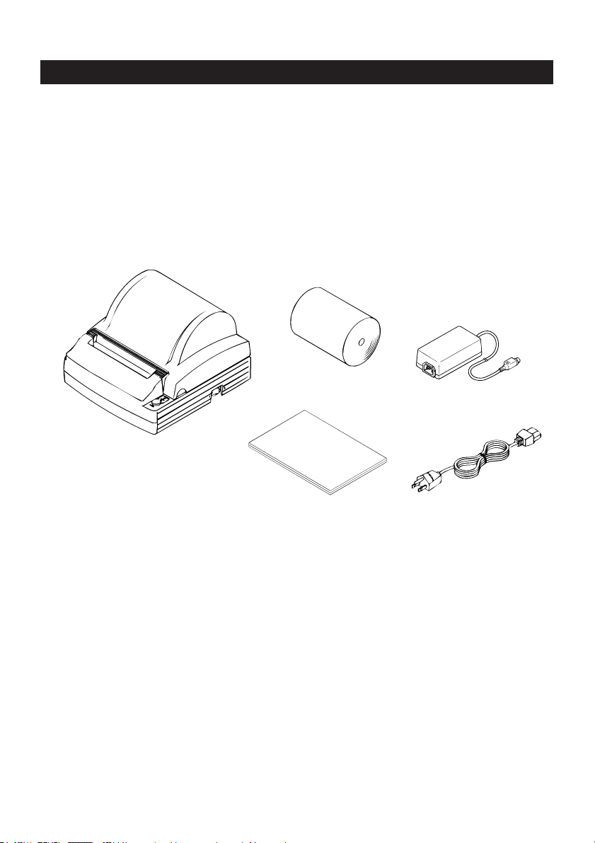
1.2 Unpacking
When unpacking the printer, confirm that the following are provided:
• Printer ............................................................................................ 1 unit
• Sample paper roll ......................................................................... 1 piece
• AC adapter ..................................................................................... 1 piece
• AC power cord .............................................................................. 1 piece
• User’s manual (This book) ........................................................... 1 piece
Printer
User’s manual
Sample
paper roll
AC adapter
AC power code
— 2 —
1.3 Before using the printer
Before using the printer, remove the head protective paper using the following
procedure:
1 Open the printer cover.
2 Pull the platen levers in the direction shown.
3 Pull out the protective paper in the direction of the arrow.
When the printer is not used for a prolonged period of time, insert a sheet of
printing paper in use between the platen roller and the head.
Platen lever
Printer cover
CAUTION:
• Install the printer on a flat, sturdy table.
• Do not install the printer near a heater or in a place exposed to direct sunlight.
• Do not use the printer in a high-temperature, high-humidity, or heavily contaminated
environment.
• Do not use the printer in an environment where condensation may occur. If
condensation should occur, leave the power turned off until condensation evaporates
completely.
— 3 —

2. BASIC SPECIFICATIONS
2.1 Model Classification
The printer models are classified by the following designation method:
iDP3240 - R F 120
Model Name
Attached power cord spec
120: For AC 120 V
230: For AC 230 V
Character Set
F: International
Interface
R: Serial (RS-232C)
P: Parallel
(IEEE 1284 compliant)
* Dedicated adapter type and power cord:
31AD-U (AC 120 V 3-wire cord)
31AD-E (AC 230 V Class I cord)
— 4 —
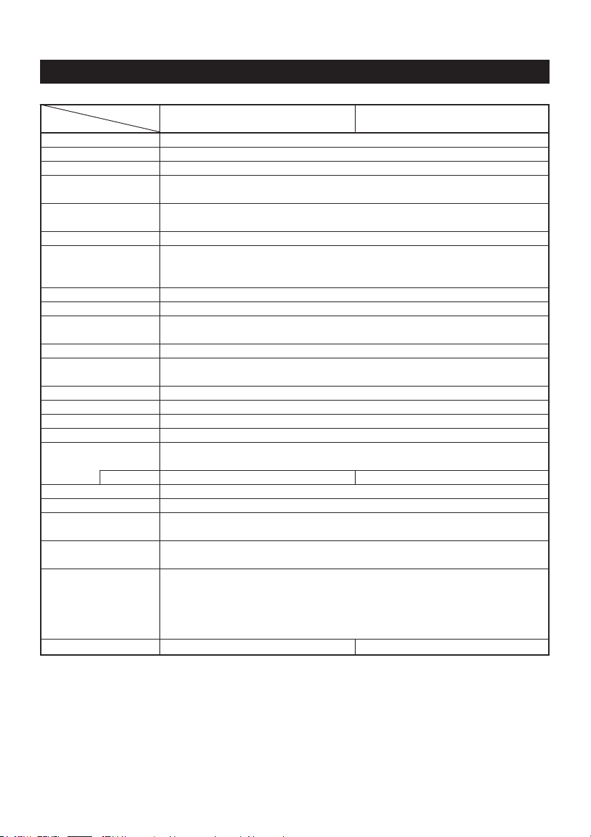
2.2 Basic Specifications
Item iDP3240-PF120 iDP3240-PF230
Print method Line thermal dot print method
Print width 104 mm/832 dots
Dot density 8 dots/mm (203 dpi)
Print speed 80 mm/sec (Fastest, printing ASCII, print density level 2, applicable to
Number of print Font A: 69/60 columns (12 × 24)
columns*
Character size Font A: 1.25 × 3.00 mm; Font B: 0.88 × 3.00 mm
Character type Alphanumeric characters, International characters, Codepages PC437,
Logo registration/print Capable of registering user-defined characters and logos into flash memory.
NV bit map data area 256K bytes
Types of bar code UPC-A/E, JAN (EAN) 13/8 columns, ITF
Line spacing 4.23 mm (1/6 inches); selectable using commands.
Paper Thermal paper roll: 112 mm +0/–1 × φ 83 mm (See “2.3 Print Paper
Interfacing
Input buffer 64K bytes (4K bytes selectable with a DIP switch)
Supply voltage DC 24 V ±7%
Power consumption Approx. 100 W
AC adapter spec. Rated input: AC 120 to 240 V, 50/60 Hz, 120 VA
Weight Main body: Approx. 1.3 kg; AC adapter: Approx. 0.45 kg
Outside dimensions 186 (W) × 201 (D) × 123 (H) mm
Operating temperature 5 to 40°C; 35 to 85% RH (No condensation)
and humidity
Storage temperature –20 to 60°C; 10 to 90% RH (No condensation)
and humidity
Reliability Print head life: Pulse resistance 1 × 10⁸ pulses (Print ratio 12.5%)
Safety Standard*
Model iDP3240-RF120 iDP3240-RF230
printing of 60 or fewer columns)
1
Type 31AD-U 31AD-E
Font B: 92/80 columns (9 × 24)
Katakana, PC850, PC860, PC863, PC865, PC852, PC866, PC857, and Windows
codepage
CODE 39, CODE 128, CODABAR, CODE 93
Specifications”.)
Serial (RS-232C), Parallel (IEEE1284 compliant, Bi-directional communication)
Rated output: DC 24 V, 1.9 A
Wear resistance 100 Km (At normal temperature/humidity
Auto cutter life: 500,000 times of cutting (At normal temperature/humidity
2
with recommended paper used)
with recommended paper used)
UL, C-UL, FCC Class A TUV, GS, CE marking
*1The number of print columns can be selected with the DIP switch.
2
*
Represents the safety standards acquired when CITIZEN SYSTEMS-made
adapters (31AD series) are used.
— 5 —

2.3 Print Paper Specifications
2.3.1 Recommended Paper
• Type: Heat sensitive paper
• Paper width: 112 + 0/– 1 mm
• Paper thickness: 65 ± 5 µm
• Roll diameter:
• Print side: Outer side of the roll (Top surface)
• Recommended paper: F220VP/ HP220A/ F230AA (From Mitsubishi Paper)
• Core size:
φ
83 mm or less
TF50KS-E2D (From Nippon Paper)
KP-50 (From Oji Paper)
or equivalent types of paper
φ
12 mm (Inside diameter); φ18 mm (Outside diameter)
CAUTION:
• Use of paper other than the specified papers may cause a difference in print density
from the CITIZEN SYSTEMS specifications. In that case, you can select an appropriate
print density with a DIP switch. (See “5. SETTING DIP SWITCHES”)
• Do not stick the end of paper to the core with adhesive paste.
• Avoid allowing the surface of paper to contact with chemicals or oils; otherwise, it
may get colored or the printed data on it may become erased.
• Avoid scraping on the surface of paper with your nail or a metal object; otherwise,
the surface of heat-sensitive paper may get colored.
• Heat-sensitive paper starts getting colored at approx. 70°C; so, be careful not to
expose the paper to the effects from heat, humidity, or sunlight.
— 6 —
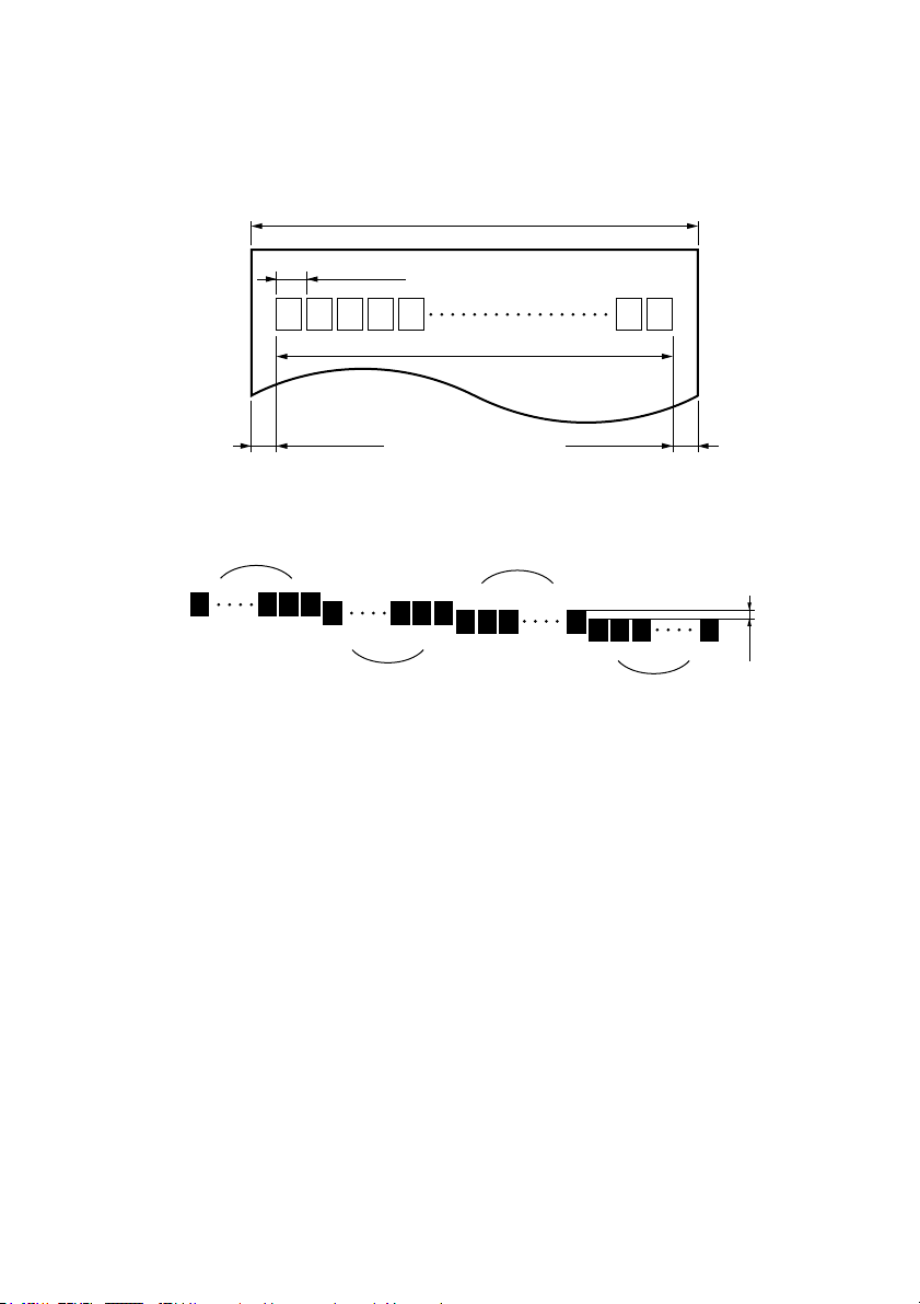
2.3.2 Print Position and Barcode Printing
Roll paper width 112 mm provided:
Paper width 112 mm applies to printing area 103.5 mm (832 dots), and both left
and right margins each ca. 4.25 mm.
Paper width 112 mm
0.125 mm
Print area 103.5 (90) mm
4.25 (11) mm 4.25 (11) mm
The values in ( )
are for when the
60 column format
is used.
Figure 1 Printing Area 1
field 1
1
192
193 448
field 2
field 3
449 704
705 832
field 4
Slight shift
possible.
Figure 2 misaligned printing
Note: Between the left and right margins, four dot fields of the heating element are
available: Dot field 1 is comprised of dots 1 - 192, dot field 2 of dots 193 448, dot field 3 of 449 - 704, and dot field 4 of 705 - 832. The printing position
of each dot field is slightly shifted relative to its adjacent dot fields, as shown
in Figure 2. This means that if a ladder bar code is printed over two adjacent
dot fields, it would appear “stepped” up or down in the middle, possibly
affecting the reading of the bar code adversely. So, be sure to avoid printing
bar codes over two adjacent dot fields.
— 7 —
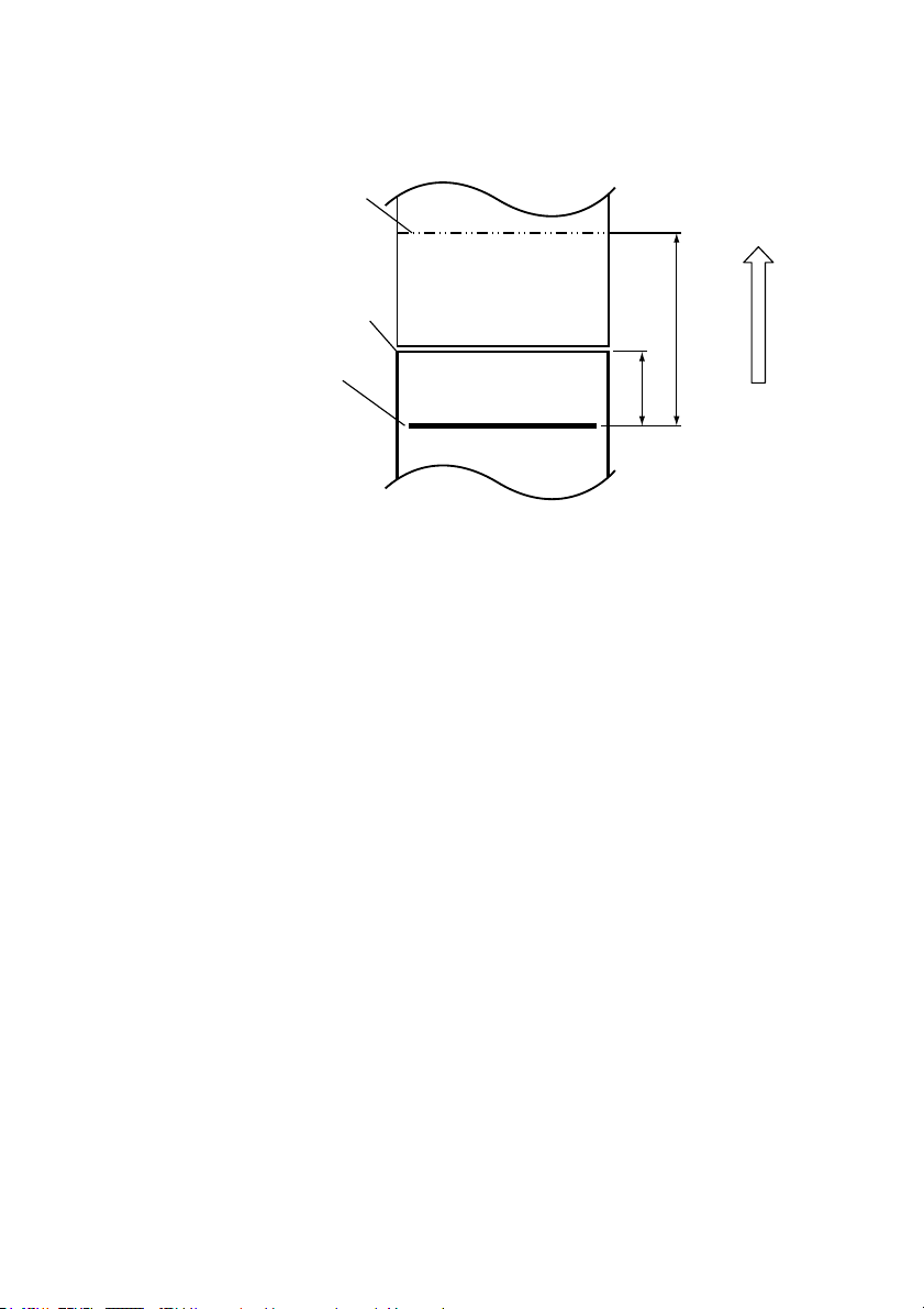
2.3.3 Cutter Position
Paper outlet slot
Auto cutting position
Top print line
Approx.
15.5 mm
Paper feed direction
Approx. 42 mm
— 8 —
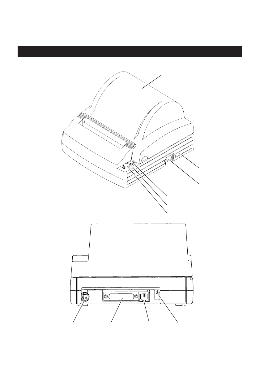
3. OUTER APPEARANCE AND COMPONENT PARTS
3.1 iDP3240
Printer cover
Top cover
Power switch
POWER lamp
ERROR lamp
FEED switch
Power
Connector
Interface
Connector
Drawer Kick-Out
Connector
— 9 —
Grounding
Terminal
4. OPERATION
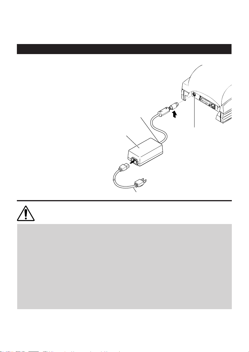
4.1 Connecting the AC Adapter and AC Power Cord
Turn off the power of the printer.
1
With the flat side of the AC adapter’s
cable connector facing upward,
2
insert the cable connector into the
power connector on the back side of
the printer.
Connect the AC power cord to the
AC adapter of the printer or the AC
3
adapter, and insert the AC powercord plug into a suitable wall outlet.
Cable
connector
AC adapter
AC power cord
Flat side
Power
connector
CAUTION:
• Do not use any AC adapter other than specified.
• When connecting or disconnecting the cable connector of the AC adapter, always pull
on the connector, not on the cable.
• The AC power cord should be connected to a wall outlet separated from others used
by other equipment which tend to emit noise.
• Avoid pulling on the AC adapter cord, or the cord may be damaged or broken, causing
a fire, electric shock.
• When the thunder rumbles nearby, disconnect the AC adapter from the wall outlet to
avoid using the printer; otherwise, a thunderbolt may cause a fire or electric shock.
• Avoid placing the AC adapter cord near a heating device; otherwise, the cover of the
cord may melt, causing a fire or electric shock.
• When you are not going to use the printer for a long period of time, disconnect the AC
adapter from the wall outlet for safety.
— 10 —

4.2 Connecting Interface Cables
Turn off the power of the printer. (As
well as the host computer
1
connected.)
Orienting the interface cable
terminal correctly, insert it into the
2
interface connector.
Secure the cable terminal as shown
below.
3
Serial interface cable: Fasten the
connector with screws.
Parallel interface cable: Hold the
connector with clamps.
Connect the other end of the
interface cable to the host computer.
4
Serial interface connector
Serial interface
cable
Parallel interface connector
Clamps
Parallel interface cable
— 11 —

4.3 Connecting the Drawer Kick-Out Connector
Turn off the power of the printer.
1
Orienting the Drawer Kick-Out Cable
Connector correctly, insert it into the
2
Drawer Kick-Out Connector on the
back of the printer.
Fasten the ground wire to the
ground connector on the printer
3
with a screw.
Drawer Kick-Out Cable connector
Drawer kick-out connector
Ground wire
CAUTION:
• Do not connect any other device than the specified drawer (Solenoid) to the Drawer
Kick-Out Connector. (Do not connect a telephone line either.)
— 12 —

4.4 Setting / Replacing Paper Rolls
4.4.1 Setting Paper Rolls
Turn on the power of the printer.
1
Placing your hands on the small
hollows on both sides of the printer
2
cover, lift the cover up until it comes
to a stop.
Cut the end of the paper roll at right
angles and in a straight line.
3
Small
hollows
Good No Good No Good No Good
— 13 —

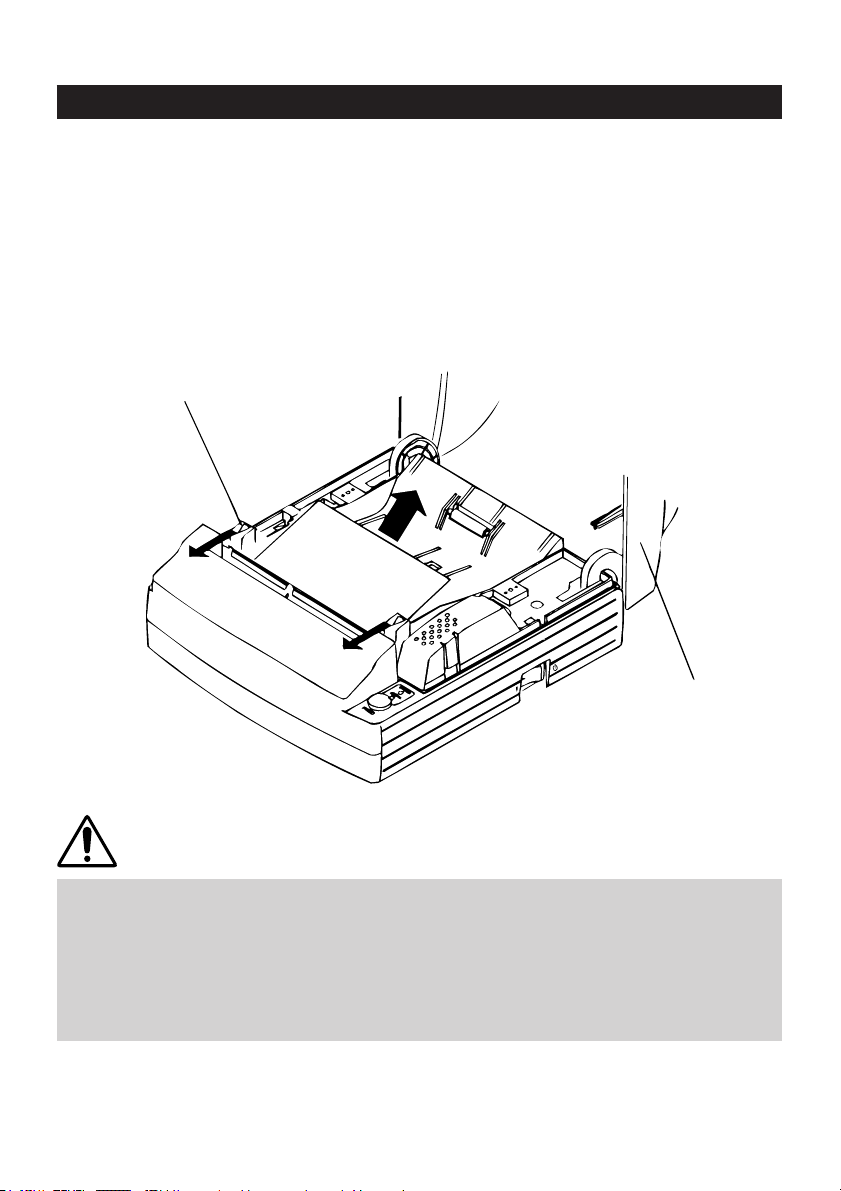
Check the winding direction of the
paper roll, and then place it into the
4
paper roll holder in the Top cover.
With the paper roll placed between
the platen levers on both sides of
5
the printer, pull the end of the paper
roll out up to the end of the Top
cover, and close the printer cover.
The paper roll is set to come out of
the printer through the paper output
slot automatically.
Cut off the portion of the paper that
is out of the printer using the
6
tear bar on the auto cutter.
Platen lever
Platen lever
Top cover
— 14 —

CAUTION:
• Always use the specified types of paper roll.
• Use of other types of paper roll may not be able to guarantee the specified print
quality or service life of the printer.
• Pull out the end of the paper roll up to the end of the upper cover.
The end of the paper should not go beyond or short of the end of the Top cover.
• When the paper roll is set, the paper end may sometimes come out folded over.
• If the paper roll is set inclined, pull the platen levers to adjust the position of the paper
roll.
• During printing, do not open the printer cover.
• If the paper fails to come out of the paper output slot, check to make sure the paper
end is properly cut, and then reset the paper roll. Also, after the printer has been used
for prolonged periods of time, the platen roller may have been covered with paper
debris, which may prevent the paper from coming out. If this happens, use a soft cloth
dabbed with ethyl alcohol to wipe the paper debris off the surface of the platen roller.
• When the paper fails to come out of the paper output slot, you can set the paper roll
using the procedure below:
1. While having the end of the paper roll inserted straight between the platen roller
and the head, press the FEED switch. The paper is pulled in by the platen roller and
guided into the auto cutter. (The of end of the paper will slightly stick out of the
paper output slot of the cutter.)
2. After closing the printer cover, the paper will be fed for a few more lines and then
automatically cut. Now, the printer is ready for printing. Remove the piece of paper
cut off.
— 15 —

4.4.2 Setting Paper Rolls when Easy Loading is Disabled (“5.2” DS1-3 ON)
Follow steps 1 to 4 in “4.4.1 Setting
Paper Rolls”.
1
Insert the end of the paper roll
straight between the platen roller
2
and the head.
The paper is automatically pulled in
by the platen roller and guided into
3
the auto-cutter. (The end of the
paper will slightly stick out of the
paper output slot of the cutter.)
After closing the printer cover, the
paper will be fed for a few more
4
lines and then automatically cut.
Now, the printer is ready for
printing. Remove the piece of paper
cut off.
Top cover
CAUTION:
• Always use the specified types of paper roll.
• Use of other types of paper roll may not be able to guarantee the specified print
quality or service life of the printer.
• If the paper is slack, roll back the paper slightly to remove the slack. If there is too
much slack, the paper may be too far from the paper sensor, possibly causing items 3
and 4 in “4.4.2 Setting Paper Rolls when Easy Loading is Disabled” to occur.
• If the paper roll is inclined, pull the platen levers to adjust the position of the paper
roll.
• During printing, do not open the printer cover.
— 16 —

4.5
Removing the Remainder of Paper Rolls
Open the printer cover.
1
Pull both platen levers in the
direction of the arrows to separate
2
the platen roller from the head, and
then pull out the paper roll.
CAUTION:
When removing the paper roll (in either direction), the platen levers must be pulled.
Platen lever
Printer cover
— 17 —

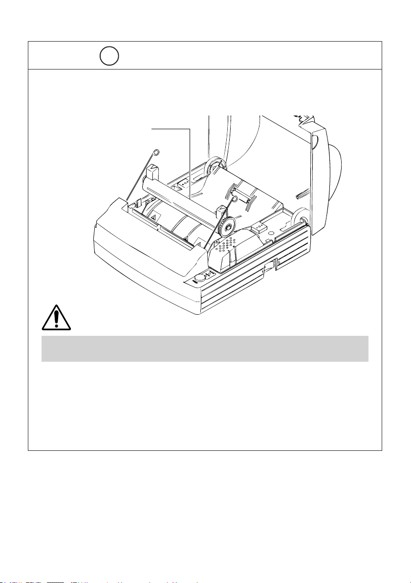
4.6 Removing Paper Jams
Turn off the power of the printer.
1
Open the printer cover.
2
Cut the paper near the paper
insertion slot.
3
Move the head springs on both sides
in the direction of arrows to unhook
4
them from the chassis hooks, and lift
them up.
Hold and lift the platen levers, and
the platen roller unit can be
5
removed.
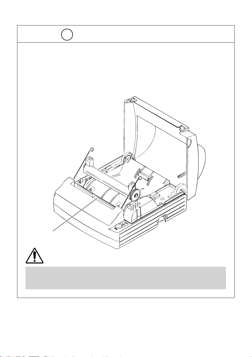
Remove any paper remaining in the
paper path.
6
Holding the platen roller unit in the
correct orientation, install it into the
7
printer with its bushes fitted in the
bush guides on the chassis.
Chassis hook
Push guide
Head spring
Platen roller unit
While pushing on the platen roller
unit lightly, lower the head springs
8
to hook them to the chassis hooks.
Push guide
CAUTION:
• Do not attempt to do anything inside the printer immediately after printing because
the head and motor are very hot.
• Do not force the head springs to move beyond their moving range.
• When removing remaining paper, do not touch the heated surface of the head with
bare hand or with metal.
• After inserting the platen roller, be sure to confirm that it has been set correctly.
• When removing the platen roller unit, the power must be turned off.
— 18 —

4.7 Releasing a Locked Cutter
Remove any paper in the paper path
following the procedure in “4.6
1
Removing Paper Jams”.
Turn on the power of printer. The
auto cutter initializes itself, returning
2
the cutter blade to the normal
position. The alarm condition is also
cleared.
If Step 2 failed to return the cutter
blade and clear the alarm, then turn
3
the printer off and using a pair of
tweezers or a screwdriver, rotate the
emergency knob located in a hole at
the bottom of the printer in the
direction shown to return the cutter
blade.
Use a pair of tweezers to remove
any remaining paper around the
4
cutter blade.
Emergency knob
CAUTION:
• Do not attempt to do anything inside the printer immediately after printing because
the head and motor are very hot.
• When removing remaining paper, do not touch the heated surface of the head with
bare hand or with metal.
• By using the DIP switch, you can either engage or disengage the cutter. When using
the printer with the cutter disengaged, make sure that the cutter blade has been
completely returned. If it has not, follow the above procedure to return it.
— 19 —

4.8 Cleaning the Print Head
Remove the platen roller unit
following the procedure in “4.6
1
Removing Paper Jams”.
Wipe off stains, such as dust and the
like, on the heating element of the
2
head using a cotton swab
impregnated with ethyl alcohol.
Replace the platen roller unit.
Platen roller unit
3
Print head
CAUTION:
• Do not touch the heat-emitting surface of the head with bare hands or metal objects.
• Do not attempt to do anything inside the printer immediately after printing because
the head and motor are very hot.
• When removing the platen roller unit, the power must be switched off.
— 20 —

4.9 Operation Panel and Error Indication
POWER lamp (Green)
Lights when the power is turned on. It blinks when a memory check error has
occurred.
ERROR lamp (Red)
Lights or blinks to show different error states.
Error indication
Memory check error Lights
Cover open
Head overheat
Paper near-end
Paper end
Cutter motor lock
Macro execution wait
Low voltage error
POWER LED
(Quick blinking)
Lights
Lights
Lights
Lights
Lights
Lights
Lights
ERROR LED Recovery method
Lights
(Slow blinking 1.5 second)
Lights
Lights
(Quick & Slow blinking)
(Slow blinking)
(Quick & Slow blinking)
High voltage error Lights
(Quick & Slow blinking)
Not recoverable
Close the cover
Recovers automatically when the
temperature returns to normal
Set a new paper roll
Set a new paper roll
Remove paper jams
Press the FEED switch
Not recoverable
Not recoverable
— 21 —
POWER lamp (Green)
POWER
ERROR lamp (Red)
ERROR
FEED switch
FEED

Description of errors
Cover open: When you open the printer cover, the cover open sensor is
activated, causing the ERROR LED to light and the printing
operation to stop. However, by making a proper setting on
the DIP switch, the paper can be fed through the printer with
the cover open.
Head overheat: To protect the print head from being overheated, the head
temperature sensor is activated if the head temperature rises
over approx. 65°C, causing the ERROR LED to blink and the
printing operation to stop. Printing resumes automatically
when the head temperature lowers below approx. 60°C.
Paper Near-end: When the diameter of the paper roll becomes small, the Paper
Near End sensor located on the side of the upper cover roller
will be activated. An ERROR light will come on to indicate that
the paper supply has become low. (See “Selecting the Paper
Sensor valid for a paper end signal output” and “Selecting
the Paper Near-end Sensor valid for print stop” described in
“10. PRINT CONTROL FUNCTIONS”.)
Paper end: When the paper roll has run out, the Paper end-Sensor
located near the print head on the paper path detects the end
of the paper roll, causing the ERROR LED to light and printing
to stop. (See “Selecting the Paper Sensor valid for a paper
end signal output” and “Selecting the Paper Near-end Sensor
valid for print stop” described in “10. PRINT CONTROL
FUNCTIONS”.)
Cutter motor lock: While the cutter motor is running, if the cutter position
detecting sensor inside the cutter unit remains ON or OFF for
approx. 1 second or more, the printer determines that the
motor has locked, causing the cutter operation and printing to
stop. (See “4.7 Releasing a Locked Cutter”.)
Low voltage error: Occurs when the voltage supplied to the printer decreases ; if
this has occurred, turn the power off immediately.
High voltage error: Occurs when the voltage supplied to the printer increases ; if
this has occurred, turn the power off immediately.
FEED switch
• Pressing this switch briefly causes one line of paper feeding. Holding down the
switch causes continuous paper feeding.
• While a macro is waiting to be executed, pressing the switch causes the macro
to be executed.
— 22 —

4.10 Self Printing
Performing Self Printing
If you press the POWER switch while holding down the FEED switch, self printing
is performed.
POWER
ERROR
FEED
POWER lamp (Green)
ERROR lamp (Red)
FEED switch
POWER switch
— 23 —

4.11 Hexadecimal Dump
Hexadecimal dump function allows data sent from the host computer to be printed in
hexadecimal numbers as well as in characters corresponding to the numbers.
Starting hexadecimal dump
Open the top cover.
1
While pressing the FEED switch, turn
on the power of the printer “
2
When you close the cover “➁”, a
message “Hexadecimal Dump” is
3
printed on paper, and then the data
received afterward is printed in
hexadecimal numbers and the
corresponding characters.
• If a character is not available
corresponding to the data received,
“ . ” is printed instead.
• During hexadecimal dump, no
other functions than DLE EOT and
DLE ENQ work.
• If the data received is not enough
for a full line, pressing the FEED
switch causes the line to be
printed.
➀”.
<Example of hexadecimal dump>
=== Hexadecimal Dump ===
Quitting hexadecimal dump
After hexadecimal printing, this
function is terminated when you
4
turn off the power or when a reset
signal is received from the interface.
— 24 —

5. SETTING DIP SWITCHES
5.1 Location of DIP Switches
To access the DIP switches, follow these steps:
Turn off the power of the printer.
1
Disconnect the Power Unit
Connector.
2
Remove the back cover.
(Unfasten the two screws and lift
3
the back cover in the direction of the
arrow.)
DS1
IC2
12345678
ON
ON
DS2
12345678
— 25 —
Parallel Interface
IC2
ON
DS2
DS3
12345678
DS4
12345678
ON
DS1
Serial Interface
1432
1432

5.2 Table for Setting DIP Switches
DIP switch 1
No. Function ON OFF Factory setting
1 Auto cutter Available Not available ON
2 Cover open Invalid Valid OFF
3 Easy Loading Invalid Valid OFF
4 Print columns
5 CR mode LF Operation Ignored OFF
6 Input buffer 4K bytes 64K bytes OFF
7
8 OFF
Print density See the table below
Print density (DIP switch 1)
No. (Light) (Standard) (Slightly dark) (Dark)
Print density Level 1 Level 2 Level 3 Level 4
7 OFF ON OFF ON
8 OFF OFF ON ON
Note: If print density is set to level 2 or over, print speed may decrease.
60 columns 69 columns
OFF
ON
— 26 —

DIP switch 2
No. Function ON OFF Factory setting
1 Character code OFF *
2 Character code
3 Character code OFF *
4 Character code OFF *
5 JIS/Shift JIS Shift JIS JIS OFF
Condition for BUSY Reception
6
to occur buffer full
7 Unused ——OFF
8 Unused ——OFF
See the table below.
• Off-line
• Reception
buffer full
OFF *
OFF
* : Depends on destinations.
Selection of Character Code tables (DIP switch 2)
Code page
No.
Codepage PC437 (USA, European Standard)
Codepage Katakana (Japanese) ON OFF OFF OFF
Codepage PC850 (Multilingual) OFF ON OFF OFF
Codepage PC860 (Portuguese) ON ON OFF OFF
Codepage PC863 (Canadian-French) OFF OFF ON OFF
Codepage PC865 (Nordic) ON OFF ON OFF
Codepage PC852 (Eastern Europe) OFF ON ON OFF
Codepage PC866 (Russian) ON ON ON OFF
Codepage PC857 (Turkish) OFF OFF OFF ON
Windows Codepage ON OFF OFF ON
Not defined ————
•————
Blank page ON ON ON ON
1234
OFF OFF OFF OFF
“Blank page”is an area for user registration, and is blank (Space) by default.
When “Katakana” is selected, the international character is set for Japanese.
— 27 —

DIP switch 3
No. Function ON OFF Factory setting
1 Bit length 7 bits 8 bits OFF
2 Parity Available Not available OFF
3 Odd /Even Even number Odd number OFF
4 Communication mode XON/XOFF DTR/DSR OFF
DIP switch 4
No. Function ON OFF Factory setting
1 Baud rate
2 Baud rate ON
3 DSR Reset DSR OFF
4 INIT Reset — OFF
See the table below.
OFF
Baud rate (DIP switch 4)
Baud rate
No.
2400 OFF OFF
4800 ON OFF
9600 OFF ON
19200 ON ON
12
Note: Dip switches 3 and 4 are only for serial interface.
— 28 —

6. PARALLEL INTERFACE
6.1 Bidirectional Parallel Interface (IEEE1284)
6.1.1 Compatibility Mode (Host → Printer communication :
Centronics compliant)
• General description
This printer provides Compatibility Mode, which specifies the Centronics
interface conventionally used for a wide variety of applications.
• Specifications
Data transfer method: 8-bit parallel
Synchronizing method: Controlled by nStrobe signal externally supplied
Handshaking: Handled by nAck and Busy signals
Signal level: All signals are C-MOS compatible
6.1.2 Reverse Mode (Printer → Host communication)
Data transfer from the printer to the host computer is conducted in Nibble or Byte
Mode. (For details, See “APPENDIX 2. BIDIRECTIONAL PARALLEL INTERFACE”.)
Outline
The reverse mode has been devised to handle data transfer from an
asynchronous printer controlled by a host computer.
In Nibble Mode, data is transferred, 4-bits (A nibble) at a time, using traditional
control lines. In Byte Mode, data is transferred by making 8-bit data lines bidirectional. Note that either mode cannot work simultaneously with Compatibility
Mode, thus resulting in half-duplex transmission. (For details, See “APPENDIX 2.
BIDIRECTIONAL PARALLEL INTERFACE”.)
— 29 —

6.1.3 Connector Pin Configuration
Pin Source Compatibility Mode Nibble Mode Byte Mode
1 Host nStrobe HostClk HostClk
2 Host/Ptr Data0(LSB) Data0(LSB) Data0(LSB)
3 Host/Ptr Data1 Data1 Data1
4 Host/Ptr Data2 Data2 Data2
5 Host/Ptr Data3 Data3 Data3
6 Host/Ptr Data4 Data4 Data4
7 Host/Ptr Data5 Data5 Data5
8 Host/Ptr Data6 Data6 Data6
9 Host/Ptr Data7(MSD) Data7(MSD) Data7(MSD)
10 Printer nAck PtrClk PtrClk
11 Printer Busy PtrBusy/Data3.7 PtrBusy
12 Printer PEerror AckDataReq/Data2.6 AckDataReq
13 Printer Select Xflag/Data1.5 Xflag
14 Host nAutoFd HostBusy HostBusy
15 NC ND ND
16 GND GND GND
17 FG FG FG
18 Printer +5V +5V +5V
19 GND GND GND
20 GND GND GND
21 GND GND GND
22 GND GND GND
23 GND GND GND
24 GND GND GND
25 GND GND GND
26 GND GND GND
27 GND GND GND
28 GND GND GND
29 GND GND GND
30 GND GND GND
31 Host nInit nInit nInit
32 Printer nFault nDataAvail/Data0.4 nDataAvail
33 GND ND ND
34 Printer DK_STATUS ND ND
35 Printer +5V ND ND
36 Host nSelectIn 1284-Active 1284-Active
NC: Not Connected
ND: Not Defined
Applicable connectors
Printer side: 57LE-40360 (Amphenol) or equivalent
Cable side: 57-30360 (Amphenol) or equivalent
— 30 —

CAUTION:
• The first letter “n” of each signal name indicates that the signal is active “L”.
• If any one of the above signals is not available, bidirectional communication cannot be
accomplished.
• In interfacing signals, be sure to use twist-paired wires for signal lines, and the return
side must be connected to signal ground level.
• All interfacing conditions are specified based on C-MOS level and must satisfy the
following characteristics. Also, specify the rising and falling time of each signal as 0.5
µs.
• Avoid transferring data by ignoring nAck or Busy signal; otherwise, the data may be
erased.
• Make the interface cables as short as necessary.
6.2 Description of Input and Output Signals
6.2.1 Input and Output Signals
Input signals to the printer
• Data: An 8-bit parallel signal. (Active “High”)
• nStrobe: A strobe signal to help read 8-bit data. (Active “Low”)
• nInit: A signal to reset the entire printer functions. (Active “Low”)
• nSelectIn: This signal is made “High” when the printer is changed to IEEE
1284 mode.
Output signals from the printer
• nAck: An 8-bit data request signal, which is output at the end of a Busy
signal. (Active “Low”)
• Busy: A signal to indicate a busy state of the printer. Input new data
when this signal is “Low”. (Active “High”)
• nFault: This signal becomes “Low” when alarmed. At this time, all control
circuits in the printer are deactivated. (Active “Low”)
• PEerror: A signal to indicate that the paper supply has become low or has
run out completely. (Active “High”)
• DK_STATUS: This signal becomes “High” when the switch is open, and “Low”
when it is closed.
Power related signal
• +5 V: A 5 V signal, which is pulled up by a 3.3 KΩ resistor.
• GND: Common ground on circuits.
— 31 —

6.2.2 Electrical Characteristics
Input signal level (nStrobe, Data 0-7)
All the input signals are at the C-MOS level.
“HIGH” level: 4.0 V minimum
“LOW” level: 0.9 V maximum
Output signal level
All the output signals are at the C-MOS level.
“HIGH” level: 2.4 V minimum
“LOW” level: 0.4 V maximum
Input and output conditions
All the input signals, Data 0-7, are each pulled up with 50 kΩ resistor, and the
other input signals are each pulled up with a 3.3 kΩ resistor.
[Host Side][Printer Side]
Vcc
Twisted Pair Wire
All the output signals, Data 0-7, are each pulled up with a 50 kΩ resistor, and the
other output signals are each pulled up with a 3.3 kΩ resistor.
[Printer Side] [Host Side]
Vcc
Twisted Pair Wire
— 32 —

6.2.3 Timing Chart (Compatibility Mode)
Data input and print timing
Power
Data
T6
T5
T1
T2
T4
T3
T1, T2, T3: 0.5 µs MIN
T4: 270 ns MAX
T5: 2.3 µs TYP
T6: 500 ms MIN
(At power- on)
nStrobe
Busy
nAck
6.2.4 Data Reception Control
When the Busy signal is at “LOW”, the printer can receive data from the host
computer, but when at “HIGH”, data reception is not possible.
6.2.5 Buffering
Since the printer can buffer 64K bytes of data, the host computer is immediately
made free.
— 33 —

7. SERIAL INTERFACE
7.1 Specifications
(1) Synchronizing system
Asynchronous
(2) Baud rate
2400, 4800, 9600, or 19200 bps (User selectable)
(3) Configuration of one word
Start bit: 1-bit
Data bits: 7 or 8-bits (User selectable)
Parity bit: Odd, even, or none (User selectable)
Stop bit: 1-bit or more
(4) Signal polarity
RS-232C
• Mark = Logic “1” (–3 V to –12 V)
• Space = Logic “0” (+3 V to +12 V)
(5) Received data (RD signal)
RS-232C
• Mark = 1
• Space = 0
(6) Reception control (DTR signal)
RS-232C
• Mark: Data transfer disabled
• Space: Data transfer enabled
(7) Transmission control (TD signal)
DC1 code (11H)X-ON: Data reception enabled
DC3 code (13H)X-OFF: Data reception disabled
— 34 —

7.2 Connector Pin Configuration
No. Signal name Input/output Function
1FG — Grounding for safety
2 TD Output Transferred data
3 RD Input Received data
4 RTS Output Same as DTR
6 DSR Input
7 GND — Ground for signals
20 DTR Output Printer Busy signal
25 INIT Input Reset (Selected with a DIP switch)
Applicable connectors (D-Sub connectors)
Printer side: 17LE-13250 (DDK) or equivalent
Cable side: 17JE-23250 (DDK) or equivalent
Data set ready or reset
(Selected with a DIP switch)
CAUTION:
• Signals for RS-232C are specified based on EIA RS-232C.
• While data is not being transferred, always maintain the received data in a mark state.
— 35 —

7.3 Description of Input and Output Signals
7.3.1 Input and Output Signals
(1) RD
This is a serial reception data signal. When a framing error, overrun error or
parity error occurs, the data containing the error is printed as a “?”.
(2) DTR, RTS
When this signal is Ready, you can write data or commands into the input buffer.
If you do so while the signal is Busy, an overrun error occurs, and the previously
written data will be ignored. Data can be written into the input buffer even during
printing. A Busy signal is also issued at the time of power-on, test printing, online communication, and resetting.
(3) TD
As data is received, the remaining capacity of the printer’s input buffer decreases.
When it becomes less than 128 bytes, a DC3 (13H) (Data reception disable signal)
is output to the host computer. On the other hand, when the remaining capacity
of the input buffer increases to 256 or more bytes, a DC1 (11H)(Data reception
enable signal) is output to the host computer.
(4) DSR
During status information transmission, if DTR/DSR control is selected, the host
computer transfers data to the printer after checking this signal is a space. If DTR/
DSR control is not selected, the host computer ignores this signal and sends data
to the printer. Also, this signal can be used as a reset signal after switching a DIP
switch. (See “5.2 Table for Setting DIP Switches”.) When the pulse width of the
signal is 1 ms or longer, a reset will be applied.
(5) INIT
This signal can be used as a reset signal after switching a DIP switch. (See “5.2
Table for Setting DIP Switches”.) When the pulse width of the signal is 1 ms or
longer in space state, a reset will be applied.
(6) FG
This is a Frame Ground signal.
(7) GND
This is a common ground on circuits.
— 36 —

7.3.2 Error Detection
Detection of parity errors, framing errors, and overrun errors is provided with this
printer. When an error is detected, the data containing the error is stored in the
buffer as a “?”.
(1) Framing error
If a space state is detected at the timing of stop bit detection, this indicates that
an error has occurred. The data containing the error is stored in the buffer as a
“?”.
(2) Parity error
With parity check specified, when data is parity-checked and an error is detected,
the data containing the error is stored in the buffer as a “?”.
(3) Overrun error
If an overrun error is detected, the data containing the error is stored in the buffer
as a “?”.
7.3.3 Data Reception Control
With DTR/DSR control selected, when DTR signal becomes “Low”, the printer can
receive data from the host computer, but when it is “High”, the printer cannot
receive data. With DTR/DSR control not selected, after sending out X-ON, the
printer receives data from the host computer, but cannot receive data from the
host computer after X-OFF is sent out.
7.3.4 Buffering
When data is transferred to the input buffer, DTR and TD signals are used as
control signals.
• Refer to 7.3.1 (2) for DTR signal.
• Refer to 7.3.1 (3) for TD signal.
— 37 —

7.3.5 Electrical Characteristics
RS-232C circuit
Input (RD, DSR, INIT)
[Printer Side] [Host Side]
Equivalent to MAX232
Output (DTR, TD, RTS)
[Printer Side] [Host Side]
Equivalent to MAX232
— 38 —

8. DRAWER KICK-OUT CONNECTOR AND POWER CONNECTOR
8.1 Specifications of Drawer Kick-Out Connector
8.1.1 Drawer Kick-Out drive signal
A pulse specified by ESC p, DLE DC4 is output. In parallel interface mode, the
SW(+) state can be confirmed at No. 34 pin of the interface connector or by the
DLE EOT, GS a and GS r commands at the serial/parallel interface.
8.1.2 Electrical characteristics
• Drive voltage: DC 24 V
• Drive current: 0.8 A maximum (Within 510 ms)
• SW signal: Signal level “L” = 0 to 0.5 V
“H” = 3 to 5 V
8.1.3 Connector Pin Configuration
Function
61
1
2
3
4
5
6
SignalNo.
FG
DRAWER 1
DRSW
VDR
DRAWER 2
GND
Frame Ground
Drawer 1 drive signal
Drawer switch input
Drawer drive power supply
Drawer 2 drive signal
Common ground on circuits
Connector used: TM5RJ3-66 (Hirose) or equivalent
Applicable connector: TM3P-66P (Hirose) or equivalent
CAUTION:
• No output is produced while printing.
• The drawers 1 and 2 cannot be driven simultaneously.
• A solenoid used for the drawer should be of 36 Ω or more. The output current should
be kept at 0.8 A or less; otherwise, breakdown or burning could occur.
• This connector cannot be connected to a telephone line. Do not connect to anything
other than the solenoid.
— 39 —

8.1.4 Drive Circuit
1
2
3
+5V
VDR
4
5
6
8.2 Specifications of the Power Connector
The following shows the power connector from the dedicated AC adapter.
Pin configuration of Power connector
(Pin number and function)
GND
2
FG
3
1
N.C
+24V
Power connector: TCS7960-53-2010 (Hosiden) or equivalent
Applicable connector: TCP8927-63-1100 (Hosiden) or equivalent
TCP8927-53-1100 (Hosiden) or equivalent
— 40 —

9. MAINTENANCE AND SERVICE
For the information on maintenance and service, please contact our dealer.
— 41 —

10. PRINT CONTROL FUNCTIONS
10.1 Command List
No.
Command
1 HT Horizontal tab S.P.
2 LF Printing and paper feed S.P.
3 CR Back to printing S.P.
4FF
5 CAN Canceling print data in PAGE MODE P
6 DLE EOT Sending status in real-time S.P.
7 DLE ENQ Real-time request to printer S.P.
8 DLE DC4 Outputting specified pulse in real-time S.P.
9 ESC FF Printing data in PAGE MODE P
10 ESC SP Setting the right spacing of the character S.P.*
11 ESC ! Collectively specifying the printing mode S.P.
12 ESC $ Specifying the absolute positions S.P.
13 ESC %
14 ESC & Defining the download characters S.P.
15 ESC
16 ESC - Specifying/Canceling underline S.P.
17 ESC 2 Specifying 1/6-inch line feed rate S.P.
18 ESC 3 Setting line feed width S.P.*
19 ESC = Data input control S.P.
20 ESC ? Deleting download characters S.P.
21 ESC @ Initializing the printer S.P.
22 ESC D Setting horizontal tab position S.P.
23 ESC E Specifying/Canceling Emphasis Printing S.P.
24 ESC G
25 ESC J Printing and feeding paper S.P.*
26 ESC L Selecting PAGE MODE S
27 ESC M Selection of character fonts S.P.
28 ESC R Selecting the international character set S.P.
29 ESC S Selecting STANDARD MODE P
In the Mode column: S = STANDARD MODE, P = PAGE MODE
Printing in PAGE MODE and returning to
STANDARD MODE
Specifying/Canceling download character set
Specifying the bit image mode S.P.
*
Specifying/Canceling Double strike printing
* shows the command affected by GS P.
Function Mode Code Page
<09>H
<0A>H
<0D>H
P
<0C>H
<18>H
<10>H<04>H<n>
<10>H<05>H<n>
<10>H<14>H<n>
<m><t>
<1B>H<0C>H
<1B>H<20>H<n>
<1B>H<21>H<n>
*
<1B>H<24>H<n1>
<n2>
S.P. <1B>H<25>H<n>
<1B>H<26>H<s>H
<n><m>[<a><p1>
<p2> ⋅ ⋅ <ps×a>]
m-n+1
<1B>H<2A>H<m>
<n1><n2>[<d>]k
<1B>H<2D>H<n>
<1B>H<32>H
<1B>H<33>H<n>
<1B>H<3D>H<n>
<1B>H<3F>H<n>
<1B>H<40>H
<1B>H<44>H [<n>]k<00>
<1B>H<45>H<n>
S.P.
<1B>H<47>H<n>
<1B>H<4A>H<n>
<1B>H<4C>H
<1B>H<4D>H<n>
<1B>H<52>H<n>
<1B>H<53>H
46
47
48
49
50
51
54
55
56
57
59
61
63
64
66
68
69
70
71
72
73
74
75
76
77
78
79
80
81
— 42 —

No.
Command
30 ESC T
31 ESC V
32 ESC W Defining the print area in PAGE MODE P*
33 ESC \ Specifying the relative position S.P.*
34 ESC a Aligning the characters S.P.
35 ESC c3
36 ESC c4
37 ESC c5 Enabling/Disabling the panel switches S.P.
38 ESC d
39 ESC p Generating the specified pulses S.P.
40 ESC t Selecting the character code table S.P.
41 ESC {
42 GS ! Specifying the character size S.P.
43 GS $
44 GS
45 GS ( A Execution of test printing S
46 GS / Printing the downloaded bit image S.P.
47 GS : Starting/Ending macro definition S.P.
48 GS B
49 GS H
50 GS I Sending the printer ID S.P.
51 GS L Setting the left margin S
52 GS P Specifying the basic calculation pitch S.P.
53 GS V Cutting the paper S.P.*
In the Mode column: S = STANDARD MODE, P = PAGE MODE
Selecting the character printing direction
in PAGE MODE
Specifying/Canceling 90°-right-turned
characters
Selecting the Paper Sensor valid for
a paper end signal output
Selecting the Paper Near-end Sensor valid
for print stop
Printing and feeding the paper by “n” lines
Specifying/Canceling the inverted characters
Specifying the absolute vertical position
of characters in PAGE MODE
Defining the download bit image S.P.
*
Specifying/Canceling the black/white
inverted printing
Selecting of printing position of HRI
characters
Function Mode Code Page
S.P.
S.P.
S.P.
S.P.
S.P.
* shows the command affected by GS P.
P
<1B>H<54>H<n>
S
<1B>H<56>H<n>
<1B>H<57>H<xL><xH>
<yL><yH><dxL><dxH>
<dyL><dyH>
<1B>H<5C>H<nL><nH>
<1B>H<61>H<n>
<1B>H<63>H<33>H
<n>
<1B>H<63>H<34>H
<n>
<1B>H<63>H<35>H
<n>
<1B>H<64>H<n>
<1B>H<70>H<m>
<n1><n2>
<1B>H<74>H<n>
S
<1B>H<7B>H<n>
<1D>H<21>H<n>
<1D>H<24>H<nL>
*
P
<nH>
<1D>H<2A>H<n1>
<n2>[<d>]n1×n2×8
<1D>H<28>H<41>H
<pL><pH><n><m>
<1D>H<2F>H<m>
<1D>H<3A>H
<1D>H<42>H<n>
<1D>H<48>H<n>
<1D>H<49>H<n>
<1D>H<4C>H<nL>
*
<nH>
<1D>H<50>H<x>
<y>
(
1)<1D>H<56>H<m>
(2)<1D>H<56>H<m>
<n>
82
83
84
86
87
88
89
90
91
92
93
94
95
97
98
100
101
102
103
104
106
107
108
109
— 43 —

No.
Command
54 GS W Setting the print area width S.P.*
55 GS \
56 GS ^ Executing the macro S.P.
57 GS a
58 GS f Selecting the font of HRI characters S.P.
59 GS h Specifying the height of the bar code S.P.
60 GS k Printing the bar code S.P.
61 GS r Sending status S.P.
62 GS v0
63 GS w
Specifying the relative vertical position
of a character in PAGE MODE
Enabling/Disabling ASB (Automatic Status
Back)
Printing of raster bit image S
Specifying the horizontal size
(Magnification) of bar code
Function Mode Code Page
S.P.*
Command relative to NV memory
No.
Command
64 FS g3
Writing data into the download user NV memory
Function Mode Code Page
<1D>H<57>H<nL>
<nH>
<1D>H<5C>H<nL>
<nH>
<1D>H<5E>H<n1>
<n2><n3>
S.P.
<1D>H<61>H<n>
<1D>H<66>H<n>
<1D>H<68>H<n>
(1)<1D>H<6B>H<m>
[d1...dk]NUL
(2)<1D>H<6B>H<m>
<n>[d1...dn]
<1D>H<72>H<n>
<1D>H<76>H<30>H
<m><xL><xH>
<yL><yH>[<d>]k
S.P.
<1D>H<77>H<n>
<1C>H<67>H<33>H
<m><a1><a2><a3>
S
<a4><nL><nH>
[<d>]nL+(nH×256)
110
112
113
114
117
118
119
127
129
131
132
65 FS g4
66 FS p Printing the download NV bit images S
67 FS q Defining the download NV bit image S
In the Mode column: S = STANDARD MODE, P = PAGE MODE
Reading data from the download user NV memory
* shows the command affected by GS P.
— 44 —
<1C>H<67>H<34>H
S.P.
<m><a1><a2><a3>
<a4><nL><nH>
<1C>H<70>H<n>
<m>
<1C>H<71>H<n>H
134
136
138

10.2 Command Details
10.2.1 Description of Each Item
XXXX
[Function] The name of a command.
[Code] The string of codes comprising the command is represented
by < >H for hexadecimal numbers, < >B for binary numbers,
and < > for decimal numbers, [ ] k denotes the number of
repetition of “k” times.
[Range] Indicates the values (setting range) of argumeuts of the
command.
Note: If values outside the defined domain specified with
control codes are used, malfunctions could possibly
occur, so be sure to use the values within the defined
domain.
[Outline] Describes the functions of the command.
[Caution] Describes important points and cautionary notes, as required.
[Default] Initial values for the command if it has arguments.
[Reference] Describes commands related to the command when it is used.
[Sample Program] Describes examples of coding in Basic.
Examples are only for reference. They may vary depending
on language and version. For details, please refer to a manual
in your language.
[Print Results] Describes the print results obtained by executing the above
programs. However, the print results shown are different in scale
from actual print results.
— 45 —

10.2.2 Command Details
HT
[Function] Horizontal tab
[Code] <09>H
[Outline] Shifts the printing position to the next horizontal tab position.
• Ignored when the next horizontal tab position has not been
set.
[Caution] • The horizontal tab position is set by ESC D.
• The initial setting of horizontal tab positions is at intervals of
8 characters for font A at 9th, 17th, 25th, 33rd, columns.
[See Also] ESC D
[Sample Program]
LPRINT “0123456789012345678901”;
LPRINT CHR$(&HA);
LPRINT CHR$(&H9) + “AAA”;
LPRINT CHR$(&H9) + “BBB”;
LPRINT CHR$(&HA) ;
LPRINT CHR$(&H1B) + “D”;
LPRINT CHR$(3) + CHR$(7) + CHR$(14) + CHR$(0);
LPRINT CHR$(&H9) + “AAA”;
LPRINT CHR$(&H9) + “BBB”;
LPRINT CHR$(&H9) + “CCC” + CHR$(&HA) ;
[Print Results]
END
0123456789012345678901
AAA
AAA
BBB
BBB
CCC
← Initially set horizontal tab
← When set to the 4th, 8th, and 15th
columns
— 46 —

LF
[Function] Printing and paper feed
[Code] <0A>H
[Outline] Prints data inside the print buffer and feeds paper based on the
line feed amount having been set.
• The head of the line becomes the next print starting position.
[See Also] ESC 2, ESC 3
[Sample Program]
LPRINT “AAA” + CHR$(&HA) ;
LPRINT “BBB” + CHR$(&HA) ;
LPRINT CHR$(&HA) ;
LPRINT “CCC” + CHR$(&HA) ;
END
[Print Results]
← Print and line feed
AAA
BBB ← Print and line feed
← Line feed only
CCC ← Print and line feed
— 47 —

CR
[Function] Back to printing
[Code] <0D>H
[Outline] 1) When DSW1-5 is OFF:
This command is ignored.
2) When DSW1-5 is ON:
With data held inside the internal print buffer, printing and
line feed are performed.
Without data inside the internal print buffer, however, only
line feed is performed.
[See Also] LF
[Sample Program]
[Print Results]
LPRINT “AAA” + CHR$(&HD) ;
LPRINT “BBB” + CHR$(&HD) ;
LPRINT CHR$(&HD) ;
LPRINT “CCC” + CHR$(&HD) ;
END
AAA
← Print and line feed
BBB ← Print and line feed
← Line feed only
CCC ← Print and line feed
— 48 —

FF
[Function] Printing in PAGE MODE and returning to STANDARD MODE
[Code] <0C>H
[Outline] Executes a batch printout of the data mapped in the entire print
area, and then returns to STANDARD MODE.
[Caution] • All mapped data is erased after printout.
• The print area set up by ESC W is initialized.
• This command does not execute a paper cut.
• After this command is executed, the beginning of the line is
taken as the start position for the next print.
• This command is only effective when the PAGE MODE is
selected.
[See Also] “PAGE MODE” in APPENDIX 1
ESC FF, ESC L, ESC S
— 49 —

CAN
[Function] Canceling print data in PAGE MODE
[Code] <18>H
[Outline] Erases all data contained in the currently effective print area in
PAGE MODE.
[Caution] • This command is only effective when PAGE MODE is selected.
• If any data mapped in the previously established print area
overlaps the data in the currently set print area, the overlapped
data in the previously established area will be erased when
this command is executed.
[See Also] “PAGE MODE” in APPENDIX 1
ESC L, ESC W
— 50 —

DLE EOT n
[Function] Sending status in real-time
[Code] <10>H<04>H<n>
[Range] 1
[Outline] Sends in real-time the status specified by “n”.
[Caution] • Each status represents the current status of the printer.
n 4
n = 1: Printer status
n = 2: Status caused by an offline condition
n = 3: Status caused by an error
n = 4: Continuous paper detector status
• The status is transferred without checking whether the host is
ready to receive or busy.
• This command is executed even if the printer is in offline state,
receive-buffer full state, or error state.
• This command is dealt with when it is received.
• If a data string of <10>H<04>H<n> (1
received data, the printer acts the same way as with this
command. Therefore, the user should be reminded of this fact.
[Example]
ESC * mnL nH [d1 ... dk], where d1 = <10>H, d2 = <04>H,
d3 = <01>H.
• If ASB (Automatic Status Back) is enabled by GS a, it is
necessary to discriminate between the status due to ASB and
the status due to this command.
n 4) is present in the
— 51 —

(1) Printer status (When n = 1 is specified)
Bit Status Hex. Decimal
0 Unused (Fixed at 0) 00 0
1 Unused (Fixed at 1) 02 2
Status of pin 3 of Drawer Kick-Out
Connector = L
2
Status of pin 3 of Drawer Kick-Out
Connector = H
Online status 00 0
3
Offline status 08 8
4 Unused (Fixed at 1) 10 16
5 Undefined ——
6 Undefined ——
7 Unused (Fixed at 0) 00 0
(2)
Status caused by an offline condition (When n = 2 is specified)
Bit Status Hex. Decimal
0 Unused (Fixed at 0) 00 0
1 Unused (Fixed at 1) 02 2
Cover closed 00 0
2
Cover open 04 4
Not in paper feed state triggered by
FEED switch
3
In paper feed state triggered by FEED
switch
4 Unused 10 16
Printing is not stopped because of
“paper out” state
5
Printing is stopped because of
“paper out” state
Error not occurred 00 0
6
Error occurred 40 64
7 Unused (Fixed at 0) 00 0
00 0
04 4
00 0
08 8
00 0
20 32
Bit 5: Printing is stopped if the paper end detector detects a
“paper out” state, or if the printer is out of paper when
the Paper Near-end Sensor is enabled by ESC c 4. At this
time, bit 5 = “1”.
— 52 —

(3) Status caused by an error (when n = 3 is specified)
Bit Status Hex. Decimal
0 Unused (Fixed at 0) 00 0
1 Unused (Fixed at 1) 02 2
2 Undefined ——
Auto cutter error not occurred 00 0
3
Auto cutter error occurred 08 8
4 Unused (Fixed at 1) 10 16
Unrecoverable error not occurred 00 0
5
Unrecoverable error occurred 20 32
Auto recovery error not occurred 00 0
6
Auto recovery error occurred 40 64
7 Undefined (Fixed at 0) 00 0
Bit 3: If this error has occurred, remove the cause of the error,
and then DLE ENQ n (1
n 2) can be used to recover
from the error. However, it is not possible to recover from
any error due to a damaged cutter or circuit problem (e.g.,
broken wire).
Bit 6: If a head overheat error is detected, the printing is stopped
until the head temperature falls. At this time, bit 6 = “1”.
(4) Continuous paper detector status (When n = 4 is specified)
Bit Status Hex. Decimal
0 Unused (Fixed at 0) 00 0
1 Unused (Fixed at 1) 02 02
Paper found by Paper Near-end Sensor
2,3
Paper not found by Paper Near-end Sensor
4 Unused (Fixed at 1) 10 16
Paper found by Paper-end Sensor 00 0
5,6
Paper not found by Paper-end Sensor 60 96
7 Unused (Fixed at 0) 00 0
00 0
0C 12
[See Also] DLE ENQ, GS a, and GS r, “IDENTIFICATION OF SEND STATUS”
in APPENDIX 3
— 53 —

DLE ENQ n
[Function] Real-time request to printer
[Code] <10>H<05>H<n>
[Range] 1
[Outline] The printer responds in real-time to the requests from the host.
[Caution] • This command is only effective if an auto cutter error has
[See Also] DLE EOT
n 2
n = 1: After recovering from an error, the printer resumes
printing from the beginning of the line where the error
occurred.
n = 2: The printer clears the receive buffer and the print buffer,
and then recovers from the error.
occurred.
• If the cause of the error has not been removed completely, the
printer may not be recovered from the error status.
• This command is dealt with when it is received.
• This command is also executed even if the printer is in a
receive-buffer full state.
• If a data string of <10>H<05>H<n> (1
received data, the printer acts in the same way as with this
command. The user should, therefore, be reminded of this
fact.
[Example] Within bit image data of a bit image, etc.
ESC * m nL nH {d} k, where d1 = <10>H, d2=<05>H, d3=<01>H1.
• Even if DLE ENQ 2 is executed, the settings made by, for
example, ESC ! and ESC 3 retain the conditions when the error
occurred. A combined use of this command and ESC @ can
completely initialize the printer.
n 2) is present in the
— 54 —

DLE DC4 n m t
[Function] Outputting specified pulse in real-time.
[Code] <10>H<14>H<n><m><t>
[Range] n=1, m=0,1
1
t 8
[Outline] A signal specified with “t” is output to the connector pin
specified with “m”.
m Connector pin
0 Pin No. 2 of drawer Kick-Out Connector
1 Pin No. 5 of drawer Kick-Out Connector
[Details] • On-time and off-time are set at t × 100 msec, respectively.
• In case an error occurred during the processing of this
command, the command is ignored.
• In case (ESC p or DLE DC4 under execution), during the
processing of this command the command is ignored.
• This command will be processed as it is received.
• In specification of serial interface, the command is executed
even in offline, reception buffer full and error conditions.
• In specification of parallel interface, this command cannot be
executed while the printer is BUSY.
• This command will be valid, even if specifying the printer is
invalid due to the selection of peripheral units (ESC =).
[Caution] • If the same data string as this command is present in the
received data, the printer operates the same way as with this
command. The user should, therefore, be careful.
• The command cannot be inserted in another string of
commands which consist of codes of 2 bytes or more.
[Reference] ESC p
— 55 —

ESC FF
[Function] Printing data in PAGE MODE
[Code] <1B>H<0C>H
[Outline] Prints out all the data mapped in the entire print area in PAGE
MODE.
[Caution] • This command is only effective when PAGE MODE is selected.
• Mapped data, as well as the ESC T and ESC W settings, and
the character mapping position are held even after printing.
[See Also] “PAGE MODE” in APPENDIX 1
FF, ESC L, ESC S
— 56 —

ESC SP n
[Function] Setting the right spacing of the character
[Code] <1B>H<20>H<n>
[Range] 0
[Outline] Sets the right spacing of character to [n × basic calculation pitch].
[Caution] • If the horizontal magnification of character is set, the right
[Default] n = 0
[See Also] GS P
n 255
spacing increases with the magnification.
• The right spacing can be set separately for the STANDARD
and PAGE MODES.
• The basic calculation pitch is set by GS P. Once defined, the
right spacing is not changed if the basic calculation pitch is
changed by GS P.
• Fractions resulting from calculation are corrected with the
minimum pitch of the mechanism, and the remainder is
omitted.
• In STANDARD MODE, this command uses the horizontal basic
calculation pitch (x).
• In PAGE MODE, the basic calculation pitch used by this
command depends on the start point:
(1) If the start point specified by ESC T is top left or bottom
right, the command uses the horizontal basic calculation
pitch (x).
(2) If the start point specified by ESC T is top right or bottom
left, the command uses the vertical basic calculation pitch
(y).
• The maximum right spacing is capable of approximately 31.906
mm. A setting greater than this maximum is trimmed to the
maximum.
— 57 —

[Sample Program]
LPRINT CHR$(&H1B) + “ ” + CHR$(0) ;
LPRINT “AAAAA” + CHR$(&HA) ;
LPRINT CHR$(&H1B) + “ ” + CHR$(1) ;
LPRINT “AAAAA” + CHR$(&HA) ;
LPRINT CHR$(&H1B) + “ ” + CHR$(12) ;
LPRINT “AAAAA” + CHR$(&HA) ;
END
[Print Results]
AAAAA
← 0-dot space
AAAAA ← 1-dot space
AAAAA ← 12-dots space
— 58 —

ESC ! n
[Function] Collectively specifying the printing mode
[Code] <1B>H<21>H<n>
[Range] 0
[Outline] Printing mode is assigned.
[Caution] • With double height and double width being specified
[Default] n = 0
[See Also] ESC E, ESC –, GS !
n 255
Bit Function
0 Character Font Font A Font B
1 Undefined
2 Undefined
3 Emphasis Canceled Specified
4 Double height Canceled Specified
5 Double width Canceled Specified
6 Undefined
7 Underline Canceled Specified
Value
01
simultaneously, quadruple characters are created.
• An underline is attached to the full character width, which,
however, is not attached to the part having been skipped by
the horizontal tab or specification of absolute positions. Neither
is it attached to 90
-right-turned characters.
• The underline thickness is as specified by the <ESC –>
command. (The default setting is 1 dot thick.)
• In case characters with different vertical magnification ratios
coexist on the same line, they are printed on the same base
line.
— 59 —

[Sample Program]
LPRINT CHR$(&H1B) + “!” + CHR$($H00) + “H” ;
LPRINT CHR$(&H1B) + “!” + CHR$($H01) + “H” ;
LPRINT CHR$(&H1B) + “!” + CHR$($H08) + “H” ;
LPRINT CHR$(&H1B) + “!” + CHR$($H10) + “H” ;
LPRINT CHR$(&H1B) + “!” + CHR$($H20) + “H” ;
LPRINT CHR$(&H1B) + “!” + CHR$($HB9) + “H” ;
LPRINT CHR$(&HA) ;
END
[Print Results]
Font A
Font B
Font A + Emphasis
∨∨∨
∨∨ ∨∨
Font B + Emphasis + Quadruple + Underline
Font A + Underline
Font A + Double Width
Font A + Double Height
— 60 —

ESC $ n1 n2
[Function] Specifying the absolute positions
[Code] <1B>H<24>H<n1><n2>
[Range] 0
[Outline] The printing start position is moved to a position specified with
[Caution] The basic calculation pitch is set by GS P. After the line feed
[Default] The initial value is not defined.
[See Also] ESC \, GS P, GS \, GS $
n1 255
0
n2 255
(n1 + (n2 × 256) ) × basic calculation pitch from the beginning
(left margin) of a line.
• The moved position is divided by 256, whose quotient is taken
as “n2” and the residual as “n1”.
• Therefore, the printing start position is equal to n1 + n2 × 256
from the beginning of a line.
width is set, if the basic calculation by GS P leaves a fraction,
the fraction is corrected with the minimum pitch of the
mechanism, and the remainder is omitted.
In STANDARD MODE, this command uses the horizontal (Paper
feed direction) basic calculation pitch (x).
In PAGE MODE, this command acts differently depending on
the start point:
(1) If the start point specified by ESC T is top right or bottom
left, the command uses the vertical (Paper feed direction)
basic calculation pitch (y).
(2) If the start point specified by ESC T is top left or bottom
right , the command uses the horizontal (Perpendicular to
the paper feed direction) basic calculation pitch (x).
Specification beyond the end of the line is ignored.
— 61 —

[Sample Program]
LPRINT CHR$(&H1B) + “$” ;
LPRINT CHR$(0) + CHR$(0) + “A” ;
LPRINT CHR$(&H1B) + “$” ;
LPRINT CHR$(50) + CHR$(0) + “B” ;
LPRINT CHR$(&H1B) + “$” ;
LPRINT CHR$(0) + CHR$(1) + “C” ;
LPRINT CHR$(&HA) ;
LPRINT CHR$(&H1B) + “$” ;
LPRINT CHR$(100) + CHR$(0) + “A” ;
LPRINT CHR$(&H1B) + “\” ;
LPRINT CHR$(&HC2) + CHR$(&HFF) + “B” ;
LPRINT CHR$(&HA);
END
[Print Results]
Absolute Position Specified
0 50 100 256
↓↓
AB ↓ C
↓
BA
←
Relative Position Specified
–62
— 62 —

ESC % n
[Function] Specifying/Canceling download character set
[Code] <1B>H<25>H<n>
[Range] 0
[Outline] Specifying/canceling download characters.
[Caution] Download characters and download bit images cannot be
[Default] n = 0
[See Also] ESC &, ESC ?
[Sample Program]
SETCHR:
n 255
• Only the lowest bit (n0) is valid for n.
n0 Function
0 Canceling download character set
1 Specifying download character set
defined simultaneously.
GOSUB SETCHR
LPRINT CHR$(&H1B) + “%” + CHR$(0) ;
LPRINT “@A” + CHR$(&HA) ;
LPRINT CHR$(&H1B) + “%” + CHR$(1) ;
LPRINT “@A” +CHR$(&HA) ;
END
LPRINT CHR$(&H1B) + “&” ;
LPRINT CHR$(3) + “@” + “A”;
FOR J=1 TO 2
READ REP
LPRINT CHR$(REP) ;
FOR I=1 TO REP∗3
READ D
LPRINT CHR$(D)
NEXT I
NEXT J
RETURN
DATA 6
DATA &HEF, &H80, &H00
DATA &H80, &H80, &H00
DATA &H80, &H80, &H00
DATA &H80, &H80, &H00
DATA &HFF, &HFF, &HFF
DATA &HFF, &HFF, &HFF
DATA 12
DATA &HFF, &HFF, &HFF
DATA &H80, &H07, &HF9
DATA &H80, &HFF, &HF9
DATA &H87, &HFE, &H01
DATA &H9F, &H06, &H01
DATA &HF8, &H06, &H01
DATA &HF8, &H06, &H01
DATA &H9F, &H06, &H01
DATA &H87, &HFE, &H01
DATA &H80, &HFE, &HF9
DATA &H80, &H07, &HF9
DATA &HFF, &HFF, &HFF
[Print Results]
← Internal Character Set
← Download Character
— 63 —

ESC & s n m [a [p] s × a] m–n+1
[Function] Defining the download characters
[Code] <1B>H<26>H<s>H<n><m>[<a><p1><p2> ⋅ ⋅ <ps × a>]m-n+1
[Range] s = 3
32
n m 126
a 12 (Font A)
0
0
a 9 (Font B)
p1 ⋅ ⋅ ps × a 255
0
[Outline] Defines the fonts of download characters.
Independent download characters can be defined for Font A
and Font B.
•“s” indicates the number of bytes in vertical direction.
•“n” indicates the start character code and “m” the end
character code. To define only one character, set n=m.
• Character codes definable includes 95 ASCII codes in total in
the range of <20>H to <7E>H.
•“a” indicates the number of dots to be defined in horizontal
direction.
•“p” is the data to be defined, which indicate a pattern equal to
“a” dots in horizontal direction from the left end. The rest of
the pattern on the right side is filled with space.
The number of data to be defined is s × a.
• Download characters thus defined remain valid until
redefinition, execution of ESC @, GS
deletion by ESC ?, or turning the power OFF takes place.
[Caution] • Download characters and download bit images cannot be
defined simultaneously.
• Running this command clears the definition of the download
bit image.
[Default] Same as the internal character set.
[See Also] ESC %, ESC ?
, FS q or ESC (A,
*
— 64 —

[Example]
12dot
9dot
24dot
p1 p4
p2
p3
p5
p6
p34
MSB
p35
p36
Font A Font B
LSB
24dot
p1 p4
p2
p3
p5
p6
p25
MSB
p26
p27
LSB
Create each data bit by setting “1” for a printed dot and “0” for
an unprinted dot.
[Sample Program] Refer to Sample Program and Print Results for ESC % on
page 63.
— 65 —

ESC * m n1 n2 [ d ] k
[Function] Specifying the bit image mode
[Code] <1B>H<2A>H<m><n1><n2> [<d>] k
[Range] m= 0, 1, 32, 33
0
n1 255
0
n2 3
0
d 255
k = n1 + 256 × n2 (m = 0, 1)
k = (n1+ 256 × n2) × 3 (m = 32, 33)
[Outline] According to the number of dots specified in “n1”, “n2”, specify
the bit image of mode “m”.
• The number of dots printed is divided by 256, whose quotient
is taken as n2 and residual as “n1”.
• The total number of dots printed in the horizontal direction is
equal to n1 + (256 × n2).
• When bit image data have been input in excess of dot positions
that can be printed on one line, the excess data are discarded.
•”d” is bit image data. Bits to be printed are specified as “1”
and those not as “0”.
• The bit image modes specified by m are shown as follows:
m
0 8-dots single density 8 67 DPI 101 DPI 416
1 8-dots double density 8 67 DPI 203 DPI 832
32 24-dots single density 24 203 DPI 101 DPI 416
33 24-dots double density 24 203 DPI 203 DPI 832
Mode
Vertical Direction Horizontal Direction
No. of Dots Dot Density Dot Density Max. No. of Dots
[Caution] • When the value of m is out of the above range, the data
following after n1 is processed as normal printing data.
• After completion of bit image printing, the printer returns to
normal data processing mode.
— 66 —

[Sample Program]
LPRINT CHR$(&H1B) + “*”;
LPRINT CHR$(0) + CHR$(20) + CHR$(0);
GOSUB IMG1
LPRINT CHR$(&HA);
LPRINT CHR$(&H1B + “
LPRINT CHR$(1) + CHR$(20) + CHR$(0);
GOSUB IMG1
LPRINT CHR$(&HA);
LPRINT CHR$(&H1B) + “
LPRINT CHR$(32) + CHR$(20) + CHR$(0);
GOSUB IMG2
LPRINT CHR$(&HA);
LPRINT CHR$(&H1B) + “
LPRINT CHR$(33) + CHR$(20) + CHR$(0);
GOSUB IMG2
LPRINT CHR$(&HA);
END
IMG1:
LPRINT CHR$(&HFF);
FOR I=1 TO 18
”;
*
”;
*
”;
*
LPRINT CHR$(&H85);
NEXT I
LPRINT CHR$(&HFF);
RETURN
IMG2:
LPRINT CHR$(&HFF);
LPRINT CHR$(&HFF);
LPRINT CHR$(&HFF);
FOR I=1 TO 18
LPRINT CHR$(&H80);
LPRINT CHR$(&H00);
LPRINT CHR$(&H05);
NEXT I
LPRINT CHR$(&HFF);
LPRINT CHR$(&HFF);
LPRINT CHR$(&HFF);
RETURN
[Print Results]
← 8-dots single density
← 8-dots double density
← 24-dots single density
← 24-dots double density
— 67 —

ESC – n
[Function] Specifying/Canceling underline
[Code] <1B>H<2D>H<n>
[Range] 0
[Outline] Specifying/canceling an underline.
[Caution] • An underline is attached to the full character width. It is,
[Default] n = 0
[See Also] ESC !, FS -
[Sample Program]
n 2
48
n 50
n=0, 48 Canceling an underline
n=1, 49 Specifying an underline for 1-dot width
n=2, 50 Specifying an underline for 2-dots width
however, not attached to the part having been skipped by
horizontal tab command.
• An underline is not attached to a 90
- right-turned characters.
LPRINT CHR$(&H1B) + “-” + CHR$(0);
LPRINT “AAAAA”;
LPRINT CHR$(&H1B) + “-” + CHR$(1);
LPRINT “AAAAA” + CHR$(&HA);
END
[Print Results]
Underline Canceled
←→
AAAAAAAAAA
←→
Underline Specified
— 68 —

ESC 2
[Function] Specifying 1/6-inch line feed rate
[Code] <1B>H<32>H
[Outline] The line feed rate per line is specified by 1/6 inch.
[Caution] Line feed rate can be specified respectively for both STANDARD
MODE and PAGE MODE.
[Sample Program]
[Print Results]
LPRINT “AAAAA” + CHR$(&HA);
LPRINT CHR$(&H1B) + “3” + CHR$(0);
LPRINT “AAAAA” + CHR$(&HA);
LPRINT CHR$(&H1B) + “3” + CHR$(50);
LPRINT “AAAAA” + CHR$(&HA);
LPRINT CHR$(&H1B) + “2”;
LPRINT “AAAAA” + CHR$(&HA);
LPRINT “AAAAA”;
LPRINT CHR$(&H1B) + “J” + CHR$(100);
LPRINT “AAAAA” + CHR$(&HA);
LPRINT “AAAAA” + CHR$(&HA);
END
AAAAA
↑
1/6-inch line feed
↓
AAAAA
AAAAA
↑
0/203-inch line feed
↓
↑
50/203-inch line feed
↓
AAAAA
↑
1/6-inch line feed
↓
AAAAA
AAAAA
AAAAA
↑
100 /203-inch line feed
↓
↑
1/6-inch line feed
↓
— 69 —

ESC 3 n
[Function] Setting line feed width
[Code] <1B>H<33>H<n>
[Range] 0
[Outline] Sets the line feed width per line to [n × basic calculation pitch] .
[Caution] The line feed width can be set separately for the STANDARD
[Default] Approx 4.23 mm
[See Also] ESC 2, GS P
n 255
and PAGE MODES.
The basic calculation pitch currently set is used. Once defined,
the line feed width is not changed even if the basic calculation
pitch is changed.
Fractions resulting from calculation are corrected with the
minimum pitch of the mechanism, and the remainder is omitted.
• In STANDARD MODE, this command uses the basic calculation
pitch (y) in the paper feed direction.
• In PAGE MODE, this command acts differently depending on
the printing direction and the start point set with ESC T n:
(1) If the start point is specified at the top left or bottom right,
the command uses the basic calculation pitch (y) in the
paper feed direction.
(2) If the start point is specified at the top right or bottom left,
the command uses the basic calculation pitch (x) in a
direction perpendicular to the horizontal paper feed
direction.
The maximum settable line feed width is 1016 mm (40 inches).
A setting greater than this maximum is trimmed to the
maximum.
— 70 —

ESC = n
[Function] Data input control
[Code] <1B>H<3D>H<n>
[Range] 0
[Outline] Selecting equipment for which data input from the host is valid.
[Caution] • Even when the printer has not been selected, it can become
[Default] n = 1
n 255
• Each bit of “n” indicates as follows:
Bit Equipment
0 Printer Invalid Valid
1 Not defined
2 Not defined
3 Not defined
4 Not defined
5 Not defined
6 Not defined
7 Not defined
Value
01
BUSY state through printer operation.
• When the printer is deselected, this printer discards all the
data until it is selected with this command. (Except DLE EOT,
DLE ENQ, and DLE DC4)
— 71 —

ESC ? n
[Function] Deleting download characters
[Code] <1B>H<3F>H<n>
[Range] 32
[Outline] Deletes the downloaded characters of specified code.
[Caution] • Specifies the character code for the defined pattern to be
[See Also] ESC &, ESC %
n 126
deleted. After the deletion, internal characters are printed.
• This command deletes the code-defined pattern of the
character font selected currently.
— 72 —

ESC @
[Function] Initializing the printer
[Code] <1B>H<40>H
[Outline] Clears data stored in the print buffer and brings various settings
to the initial state (Default state).
[Caution] • The settings of DIP switches are not read again.
• Data inside the internal input buffer is not cleared.
• Macro definitions are not cleared.
• NV bit image definitions are not cleared.
• Data in the user NV memory is not cleared.
[Sample Program]
[Print Results]
LPRINT CHR$(&H1B) + “!” + CHR$(&H30);
LPRINT CHR$(&H1B) + “V” + CHR$(1);
LPRINT “AAA” + CHR$(&HA);
LPRINT CHR$(&H1B) + “@”;
LPRINT “AAA” + CHR$(&HA);
END
A
A
A
← Each setting has been
AAA
initialized by this command.
— 73 —

ESC D { n } k NUL
[Function] Setting horizontal tab position
[Code] <1B>H<44>H [<n>] k<00>
[Range] 1
[Outline] Specifying a horizontal tab position.
[Caution] When the data, <n> k, is equal to or smaller than its preceding
[Default] • Tab positions are set at eight-character intervals (9th, 17th,
[See Also] HT
[Sample Program] Refer to Sample Program and Print Results for HT on page 46.
n 255
0
k 32
•“n” indicates the number of columns from the beginning (left
margin) to the horizontal tab position. Note, however, that
“n= set position – 1”. For example, to set the position at 9th
column, n=8 is to be specified.
•“k” denotes the number of horizontal tab positions you want
to set.
• The tab position is set at a position where it is “character width
× n” from the beginning of a line. The character width, at this
time, includes the space on the right. If the horizontal
magnification ratio of characters is 2 or above, the character
width is increased correspondingly.
• Tab positions that can be specified are maximum 32.
Specifying tab positions exceeding this limit is ignored.
• <n> k, which denotes a setting position, is input in the
increasing order and ends at <00> H.
• ESC D <NUL> clears all the set tab positions. Following
clearing, the horizontal tab command is ignored.
data, <n> k-1, it is assumed that tab setting is finished. If this is
the case, the next data onward will be processed as normal
data.
When the data, <n> k, exceeds a 1-line print area, set the
horizontal tab position, as “Set column position = Maximum
print columns + 1”. The horizontal tab position does not change
even if the character width is altered after setting the horizontal
tab position.
25th columns) of Font A.
— 74 —

ESC E n
[Function] Specifying/Canceling Emphasis Printing
[Code] <1B>H<45>H<n>
[Range] 0
[Outline] Specifying/canceling the emphasized characters.
[Caution] Emphasis printing can also be specified with ESC !, but is only
[Default] n = 0
[See Also] ESC !
[Sample Program]
n 255
•“n” is valid only for the lowest bit (n0).
• Control by the lowest bit (n0) is shown as follows:
n0 Type
0 Canceling emphasis printing
1 Specifying emphasis printing
• This is effective to all characters.
• Dot configuration of a emphasized character includes one extra
dot added at its side.
• Emphasis printing can also be specified using ESC !, however,
ESC E or ESC !, whichever command is processed last, takes
precedence.
valid with the command that is set last.
LPRINT CHR$(&H1B) + “E” + CHR$(0);
LPRINT “AAABBB” + CHR$(&HA);
LPRINT CHR$(&H1B) + “E” + CHR$(1);
LPRINT “AAABBB” + CHR$(&HA);
END
[Print Results]
AAABBB
AAABBB
← Emphasis canceled
← Emphasis specified
— 75 —

ESC G n
[Function] Specifying/Canceling Double strike printing
[Code] <1B>H<47>H<n>
[Range] 0
[Outline] Specifying/canceling the double strike printing.
[Caution] Double-strike printing and emphasis printing provide completely
[Default] n = 0
[See Also] ESC E
[Sample Program]
n 255
•“n” is valid only for the lowest bit (n0).
• Control by “n” is shown as follows.
n0 Type
0 Canceling double strike printing
1 Specifying double strike printing
This is effective to all characters.
the same results.
LPRINT CHR$(&H1B) + “G” + CHR$(0);
LPRINT “AAABBB” + CHR$(&HA);
LPRINT CHR$(&H1B) + “G” + CHR$(1);
LPRINT “AAABBB” + CHR$(&HA);
END
[Print Results]
AAABBB
AAABBB
← Double strike printing canceled
← Double strike printing specified
— 76 —

ESC J n
[Function] Printing and feeding paper
[Code] <1B>H<4A>H<n>
[Range] 0
[Outline] Prints the data held in the print buffer and feeds paper by [n ×
[Caution] The line feed width can be set separately for the STANDARD
[Default] The initial value is not defined.
[Sample Program] Refer to Sample Program and Print Results for ESC 2 on
n 255
basic calculation pitch] inches. The beginning of the line is taken
as the next print start position.
and PAGE MODES.
• This command does not affect the line feed width currently
set.
• Fractions resulting from calculation are corrected with the
minimum pitch of the mechanism, and the remainder is
omitted.
• In STANDARD MODE, this command uses the basic calculation
pitch (y) in the paper feed direction.
• In PAGE MODE, this command acts differently depending on
the printing direction and the start point set with ESC T n:
(1) If the start point is specified at the top left or bottom right,
the command uses the basic calculation pitch (y) in the paper
feed direction.
(2) If the start point is specified at the top right or bottom left,
the command uses the basic calculation pitch (x) in a
direction perpendicular to the paper feed direction.
The maximum set table line feed width is 1016 mm (40 inches).
A setting greater than this maximum is trimmed to the
maximum. The beginning of the line is taken as the next print
start position.
page 69.
— 77 —

ESC L
[Function] Selecting PAGE MODE
[Code] <1B>H<4C>H
[Outline] Switches from STANDARD MODE to PAGE MODE.
[Caution] • This command is only effective if it entered at the beginning
of a line.
• This command is not effective if it is entered when in PAGE
MODE.
• STANDARD MODE is restored when printing specified by FF
is finished or when ESC S is issued.
• The character mapping start position will be the point specified
by ESC T in the print area specified by ESC W.
• The commands listed below, which have separate settings for
PAGE MODE and STANDARD MODE, are changed to the
settings for PAGE MODE use.
(1) Spacing setting: ESC SP
(2) Line feed width setting: ESC 2, ESC 3
• The following commands are valid only in PAGE MODE:
(1) ESC V Specifying/canceling 90°-right-turned characters.
(2) ESC a Aligning the characters.
(3) ESC { Specifying/canceling the inverted characters.
(4) GS L Setting the left margin.
(5) G3S W Setting the print area width.
• The following commands become invalid in PAGE MODE:
(1) FS p Printing NV bit images
(2) FS q Defining NV bit images
(3) FS g3 Writing to user NV memory
(4) GS V0 Printing raster bit images
• ESC @ restores STANDARD MODE.
[See Also] “PAGE MODE” in APPENDIX 1
FF, CAN, ESC FF, ESC S, ESC T, ESC W, GS $, GS \
— 78 —

ESC M n
[Function] Selection of character fonts
[Code] <1B>H<4D>H<n>
[Definition value] n=0, 1, 48, 49
[Outline] Selects character fonts.
n Function
0, 48 Selection of font A (12 × 24)
1, 49 Selection of font B (9 × 24)
[Details] Fonts can also be selected with ESC !, but are only valid with
the command that is set last.
[Reference] ESC !
— 79 —

ESC R n
[Function] Selecting the international character set
[Code] <1B>H<52>H<n>
[Range] 0
[Outline] Depending on the value of “n”, one of the following character
[Default] n = 0
[See Also] Character Code Table (International Character Set)
n 13
sets is specified;
n Character Set
0 U.S.A.
1 France
2 Germany
3 U.K.
4 Denmark I
5 Sweden
6 Italy
7 Spain I
8 Japan
9 Norway
10 Denmark II
11 Spain II
12 Latin America
13 Korea
— 80 —
 Loading...