


 Loading...
PA-2FE-TX and PA-2FE-FX Two-Port Fast
Ethernet Port Adapter Installation and
Configuration
Product Number: PA-2FE-TX=, PA-2FE-FX=
Platforms Supported: Cisco 7100 Series Routers, Cisco 7200 Series Routers, Cisco uBR7200 Series Routers, Cisco 7200 VXR Routers, Cisco 7201 Router, Cisco 7301 Router, Cisco 7304 PCI Port Adapter Carrier Card in the Cisco 7304 Router, Cisco 7401ASR Router, and VIP in the Cisco 7500 Series Routers
Americas Headquarters
Cisco Systems, Inc. 170 West Tasman Drive
San Jose, CA 95134-1706 USA http://www.cisco.com Tel: 408 526-4000
800 553-NETS (6387) Fax: 408 527-0883
Text Part Number: OL-3474-07
THE SPECIFICATIONS AND INFORMATION REGARDING THE PRODUCTS IN THIS MANUAL ARE SUBJECT TO CHANGE WITHOUT NOTICE. ALL STATEMENTS, INFORMATION, AND RECOMMENDATIONS IN THIS MANUAL ARE BELIEVED TO BE ACCURATE BUT ARE PRESENTED WITHOUT WARRANTY OF ANY KIND, EXPRESS OR IMPLIED. USERS MUST TAKE FULL RESPONSIBILITY FOR THEIR APPLICATION OF ANY PRODUCTS.
THE SOFTWARE LICENSE AND LIMITED WARRANTY FOR THE ACCOMPANYING PRODUCT ARE SET FORTH IN THE INFORMATION PACKET THAT SHIPPED WITH THE PRODUCT AND ARE INCORPORATED HEREIN BY THIS REFERENCE. IF YOU ARE UNABLE TO LOCATE THE SOFTWARE LICENSE OR LIMITED WARRANTY, CONTACT YOUR CISCO REPRESENTATIVE FOR A COPY.
The following information is for FCC compliance of Class A devices: This equipment has been tested and found to comply with the limits for a Class A digital device, pursuant to part 15 of the FCC rules. These limits are designed to provide reasonable protection against harmful interference when the equipment is operated in a commercial environment. This equipment generates, uses, and can radiate radio-frequency energy and, if not installed and used in accordance with the instruction manual, may cause harmful interference to radio communications. Operation of this equipment in a residential area is likely to cause harmful interference, in which case users will be required to correct the interference at their own expense.
The following information is for FCC compliance of Class B devices: The equipment described in this manual generates and may radiate radio-frequency energy. If it is not installed in accordance with Cisco’s installation instructions, it may cause interference with radio and television reception. This equipment has been tested and found to comply with the limits for a Class B digital device in accordance with the specifications in part 15 of the FCC rules. These specifications are designed to provide reasonable protection against such interference in a residential installation. However, there is no guarantee that interference will not occur in a particular installation.
Modifying the equipment without Cisco’s written authorization may result in the equipment no longer complying with FCC requirements for Class A or Class B digital devices. In that event, your right to use the equipment may be limited by FCC regulations, and you may be required to correct any interference to radio or television communications at your own expense.
You can determine whether your equipment is causing interference by turning it off. If the interference stops, it was probably caused by the Cisco equipment or one of its peripheral devices. If the equipment causes interference to radio or television reception, try to correct the interference by using one or more of the following measures:
•Turn the television or radio antenna until the interference stops.
•Move the equipment to one side or the other of the television or radio.
•Move the equipment farther away from the television or radio.
•Plug the equipment into an outlet that is on a different circuit from the television or radio. (That is, make certain the equipment and the television or radio are on circuits controlled by different circuit breakers or fuses.)
Modifications to this product not authorized by Cisco Systems, Inc. could void the FCC approval and negate your authority to operate the product.
The Cisco implementation of TCP header compression is an adaptation of a program developed by the University of California, Berkeley (UCB) as part of UCB’s public domain version of the UNIX operating system. All rights reserved. Copyright © 1981, Regents of the University of California.
NOTWITHSTANDING ANY OTHER WARRANTY HEREIN, ALL DOCUMENT FILES AND SOFTWARE OF THESE SUPPLIERS ARE PROVIDED “AS IS” WITH ALL FAULTS. CISCO AND THE ABOVE-NAMED SUPPLIERS DISCLAIM ALL WARRANTIES, EXPRESSED OR IMPLIED, INCLUDING, WITHOUT LIMITATION, THOSE OF MERCHANTABILITY, FITNESS FOR A PARTICULAR PURPOSE AND NONINFRINGEMENT OR ARISING FROM A COURSE OF DEALING, USAGE, OR TRADE PRACTICE.
IN NO EVENT SHALL CISCO OR ITS SUPPLIERS BE LIABLE FOR ANY INDIRECT, SPECIAL, CONSEQUENTIAL, OR INCIDENTAL DAMAGES, INCLUDING, WITHOUT LIMITATION, LOST PROFITS OR LOSS OR DAMAGE TO DATA ARISING OUT OF THE USE OR INABILITY TO USE THIS MANUAL, EVEN IF CISCO OR ITS SUPPLIERS HAVE BEEN ADVISED OF THE POSSIBILITY OF SUCH DAMAGES.
CCVP, the Cisco Logo, and the Cisco Square Bridge logo are trademarks of Cisco Systems, Inc.; Changing the Way We Work, Live, Play, and Learn is a service mark of Cisco Systems, Inc.; and Access Registrar, Aironet, BPX, Catalyst, CCDA, CCDP, CCIE, CCIP, CCNA, CCNP, CCSP, Cisco, the Cisco Certified Internetwork Expert logo, Cisco IOS, Cisco Press, Cisco Systems, Cisco Systems Capital, the Cisco Systems logo, Cisco Unity, Enterprise/Solver, EtherChannel, EtherFast, EtherSwitch, Fast Step, Follow Me Browsing, FormShare, GigaDrive, HomeLink, Internet Quotient, IOS, iPhone, IP/TV, iQ Expertise, the iQ logo, iQ Net Readiness Scorecard, iQuick Study, LightStream, Linksys, MeetingPlace, MGX, Networking Academy, Network Registrar, Packet, PIX, ProConnect, RateMUX, ScriptShare, SlideCast, SMARTnet, StackWise, The Fastest Way to Increase Your Internet Quotient, and TransPath are registered trademarks of Cisco Systems, Inc. and/or its affiliates in the United States and certain other countries.
All other trademarks mentioned in this document or Website are the property of their respective owners. The use of the word partner does not imply a partnership relationship between Cisco and any other company. (0704R)
PA-2FE-TX and PA-2FE-FX Two-Port Fast Ethernet Port Adapter Installation and Configuration
© 2007 Cisco Systems, Inc. All rights reserved.

|
|
|
|
|
|
|
|
C O N T E N T S |
|
|
Preface |
vii |
|
|
|
|
|
|
|
|
Document Revision History vii |
|
|
|
|
|
|||
|
Objectives |
viii |
|
|
|
|
|
|
|
|
Organization |
viii |
|
|
|
|
|
|
|
|
Related Documentation |
viii |
|
|
|
|
|
||
|
Obtaining Documentation, Obtaining Support, and Security Guidelines xi |
||||||||
|
Overview |
|
|
|
|
|
|
|
|
C H A P T E R 1 |
1-1 |
|
|
|
|
|
|
|
|
|
Port Adapter Overview |
1-1 |
|
|
|
|
|
||
|
Fast Ethernet Overview |
1-2 |
|
|
|
|
|
||
|
IEEE 802.3u 100BASE-T Specifications |
1-2 |
|
|
|
||||
|
LEDs |
1-4 |
|
|
|
|
|
|
|
|
Receptacles, Cables, and Pinouts |
1-4 |
|
|
|
|
|||
|
Network Management |
1-6 |
|
|
|
|
|
||
|
Port Adapter Slot Locations on the Supported Platforms |
1-7 |
|||||||
|
Cisco 7100 Series Routers Slot Numbering |
1-7 |
|
||||||
|
Cisco 7200 Series Routers and Cisco 7200 VXR Routers Slot Numbering 1-8 |
||||||||
|
Cisco uBR7200 Series Router Slot Numbering |
1-9 |
|
||||||
|
Cisco 7201 Router Slot Numbering |
1-10 |
|
|
|
||||
|
Cisco 7301 Router Slot Numbering |
1-10 |
|
|
|
||||
|
Cisco 7304 PCI Port Adapter Carrier Card Slot Numbering 1-11 |
||||||||
|
Cisco 7401ASR Router Slot Numbering |
1-12 |
|
||||||
|
Cisco 7500 Series Routers with VIP Slot Numbering |
1-12 |
|||||||
|
Identifying Interface Addresses |
1-16 |
|
|
|
|
|||
|
Cisco 7120 Router and Cisco 7140 Router Interface Addresses 1-17 |
||||||||
|
Cisco 7200 Series Routers and Cisco 7200 VXR Routers Interface Addresses 1-17 |
||||||||
|
Cisco uBR7200 Series Routers Interface Addresses |
1-18 |
|||||||
|
Cisco 7201 Router Interface Addresses |
1-18 |
|
||||||
|
Cisco 7301 Router Interface Addresses |
1-18 |
|
||||||
|
Cisco 7304 |
PCI Port Adapter Carrier Card Interface Addresses 1-18 |
|||
|
Cisco 7401ASR Router Interface Addresses 1-18 |
||||
|
Cisco 7500 |
Series Routers VIP Interface Addresses 1-19 |
|||
|
PA-2FE-TX and PA-2FE-FX Two-Port Fast Ethernet Port Adapter Installation and Configuration |
|
|
|
|
|
|||||
|
|
|
|
|
|
|
OL-3474-07 |
|
|
iii |
|
|
|
|
|
||

Contents
C H A P T E R |
2 |
|
Preparing for Installation |
2-1 |
|
|
|
|
|
|
|
|||
|
|
|
|
|
Required Tools and Equipment |
2-1 |
|
|
|
|
|
|
||
|
|
|
|
|
Software and Hardware Requirements |
2-2 |
|
|
|
|
||||
|
|
|
|
|
Checking Hardware and Software Compatibility |
2-2 |
|
|
|
|||||
|
|
|
|
|
Safety Guidelines 2-3 |
|
|
|
|
|
|
|
|
|
|
|
|
|
|
Safety Warnings |
2-3 |
|
|
|
|
|
|
|
|
|
|
|
|
|
Warning Definition |
2-3 |
|
|
|
|
|
|
||
|
|
|
|
|
Electrical Equipment Guidelines |
2-8 |
|
|
|
|
||||
|
|
|
|
|
Telephone Wiring Guidelines |
2-9 |
|
|
|
|
|
|||
|
|
|
|
|
Preventing Electrostatic Discharge Damage |
2-9 |
|
|
|
|||||
|
|
|
|
|
FCC Class A Compliance |
2-10 |
|
|
|
|
|
|
|
|
|
|
|
Removing and Installing Port Adapters |
|
|
|
|
|
||||||
C H A P T E R |
3 |
|
3-1 |
|
|
|
|
|||||||
|
|
|
|
|
Handling Port Adapters |
3-1 |
|
|
|
|
|
|
|
|
|
|
|
|
|
Online Insertion and Removal |
3-2 |
|
|
|
|
|
|
||
|
|
|
|
|
Warnings and Cautions |
3-3 |
|
|
|
|
|
|
|
|
|
|
|
|
|
Port Adapter Removal and Installation |
3-4 |
|
|
|
|
||||
|
|
|
|
|
Cisco 7100 Series—Removing and Installing a Port Adapter |
3-5 |
|
|
||||||
|
|
|
|
|
Cisco 7200 Series Routers and Cisco 7200 VXR Routers—Removing and Installing a Port |
|||||||||
|
|
|
|
|
Adapter 3-6 |
|
|
|
|
|
|
|
|
|
|
|
|
|
|
Cisco uBR7200 Series Routers—Removing a Port Adapter |
3-7 |
|
|
||||||
|
|
|
|
|
Cisco uBR7200 Series Routers—Installing a Port Adapter |
3-8 |
|
|
||||||
|
|
|
|
|
Cisco 7201 Router—Removing and Installing a Port Adapter |
3-9 |
|
|
||||||
|
|
|
|
|
Cisco 7301 Router—Removing and Installing a Port Adapter |
3-10 |
|
|
||||||
|
|
|
|
|
Cisco 7304 PCI Port Adapter Carrier Card—Removing and Installing a Port Adapter 3-11 |
|||||||||
|
|
|
|
|
Cisco 7401ASR Router—Removing and Installing a Port Adapter 3-13 |
|
|
|||||||
|
|
|
|
|
Cisco 7500 Series Router VIP—Removing and Installing a Port Adapter |
3-13 |
|
|||||||
|
|
|
|
|
Removing and Installing a VIP Carrier Card in the Cisco 7500 Series Router 3-14 |
|||||||||
|
|
|
|
|
Removing and Installing the Port Adapter in the VIP Carrier Card |
3-15 |
|
|||||||
|
|
|
|
|
Connecting a PA-2FE RJ-45 or SC Cable |
3-16 |
|
|
|
|
||||
|
|
|
Configuring the PA-2FE |
|
|
|
|
|
|
|
|
|
||
C H A P T E R |
4 |
|
4-1 |
|
|
|
|
|
|
|
|
|||
|
|
|
|
|
Using the EXEC Command Interpreter |
4-1 |
|
|
|
|
||||
|
|
|
|
|
Configuring the Interfaces |
4-2 |
|
|
|
|
|
|
|
|
|
|
|
|
|
Shutting Down an Interface |
4-2 |
|
|
|
|
|
|||
|
|
|
|
|
Performing a Basic Interface Configuration |
4-7 |
|
|
|
|||||
|
|
|
|
|
Checking the Configuration |
4-9 |
|
|
|
|
|
|
||
|
|
|
|
|
Using show Commands to Verify the New Interface Status |
4-9 |
|
|
||||||
|
|
|
|
PA-2FE-TX and PA-2FE-FX Two-Port Fast Ethernet Port Adapter Installation and Configuration |
|
|
|
|||||||
|
|
|
|
|
|
|
||||||||
|
|
|
|
|
|
|
|
|
|
|
|
|
|
|
|
iv |
|
|
|
|
|
|
|
|
|
|
|
OL-3474-07 |
|
|
|
|
|
|
|
|
|
|
|
|
|
|
||

Contents
Using the show version or show hardware Commands |
4-11 |
Using the show diag Command 4-14 |
|
Using the show interfaces Command 4-18 |
|
Using the ping Command to Verify Network Connectivity |
4-21 |
PA-2FE-TX and PA-2FE-FX Two-Port Fast Ethernet Port Adapter Installation and Configuration
|
OL-3474-07 |
v |
|

Contents
PA-2FE-TX and PA-2FE-FX Two-Port Fast Ethernet Port Adapter Installation and Configuration
|
vi |
OL-3474-07 |
|
|
|

Preface
This preface describes the objectives and organization of this document and explains how to find additional information on related products and services. This preface contains the following sections:
•Document Revision History, page vii
•Objectives, page viii
•Organization, page viii
•Related Documentation, page viii
•Obtaining Documentation, Obtaining Support, and Security Guidelines, page xi
Document Revision History
The Document Revision History table below, beginning with version OL-10589-05, records technical changes to this document.
Document Version |
Date |
Change Summary |
|
|
|
OL-3474-07 |
April, 2007 |
Adding Cisco 7201 router information. |
|
|
|
OL-3474-06 |
December, 2006 |
Correcting software support information. |
|
|
|
OL-3474-05 |
November, 2006 |
Correcting the RJ-45 pinout information. |
|
|
|
PA-2FE-TX and PA-2FE-FX Two-Port Fast Ethernet Port Adapter Installation and Configuration
|
OL-3474-07 |
vii |
|

Preface
Objectives
Objectives
This document describes how to install and configure the PA-2FE-TX and PA-2FE-FX two-port Fast Ethernet port adapters, hereafter referred to as the PA-2FE, which are used in the following platforms:
•Cisco 7100 series routers, consisting of the Cisco 7120 series and Cisco 7140 series
•Cisco 7200 series routers and Cisco 7200 VXR routers, consisting of the two-slot Cisco 7202, four-slot Cisco 7204 and Cisco 7204VXR, and the six-slot Cisco 7206 and Cisco 7206VXR
•Cisco uBR7200 series universal broadband routers
•Cisco 7201 router
•Cisco 7301 router
•Cisco 7304 PCI port adapter carrier card in Cisco 7304 router
•Cisco 7401ASR router
•Versatile Interface Processor (VIP) in Cisco 7500 series routers (VIP2, VIP4, VIP6-80)
Organization
This document contains the following chapters:
Section |
Title |
Description |
|
|
|
Chapter 1 |
Overview |
Describes the PA-2FE and its LED displays, cables, and |
|
|
receptacles. |
|
|
|
Chapter 2 |
Preparing for Installation |
Describes safety considerations, tools required, and |
|
|
procedures you should perform before the actual |
|
|
installation. |
|
|
|
Chapter 3 |
Removing and Installing |
Describes the procedures for installing and removing |
|
Port Adapters |
PA-2FE port adapters in the supported platforms. |
|
|
|
Chapter 4 |
Configuring the PA-2FE |
Provides instructions for configuring the PA-2FE on the |
|
|
supported platforms. |
|
|
|
Related Documentation
Your router and the Cisco IOS software running on it contain extensive features and functionality, which are documented in the following resources:
•Cisco IOS software:
For configuration information and support, refer to the modular configuration and modular command reference publications in the Cisco IOS software configuration documentation set that corresponds to the software release installed on your Cisco hardware.
Note You can access Cisco IOS software configuration and hardware installation and maintenance documentation on the World Wide Web at http://www.cisco.com, http://www-china.cisco.com, or http://www-europe.cisco.com.
PA-2FE-TX and PA-2FE-FX Two-Port Fast Ethernet Port Adapter Installation and Configuration
|
viii |
OL-3474-07 |
|
|
|

Preface
Related Documentation
•Cisco 7100 series routers:
–For an online directory to quickly access documents for Cisco 7100 series routers, refer to the
Cisco 7100 Series Documentation roadmap at the following URL:
http://www.cisco.com/en/US/products/hw/vpndevc/ps333/products_product_index09186a008 00fa142.html
–For hardware installation and configuration information refer to the Cisco 7100 Series VPN Router Installation and Configuration Guide.
•Cisco 7200 series routers:
–For an online directory to quickly access documents for Cisco 7200 series routers, refer to the
Cisco 7200 Series Routers Documentation Roadmap at the following URL:
http://www.cisco.com/en/US/products/hw/routers/ps341/products_documentation_roadmap09 186a00801c0915.html
–For hardware installation and configuration information (including the Cisco 7206 or Cisco 7206VXR as a router shelf in a Cisco AS5800 Universal Access Server), refer to the
online installation and configuration guide and quick start for your Cisco 7200 series router.
–For port adapter hardware and memory configuration guidelines, refer to the Cisco 7200 Series Port Adapter Hardware Configuration Guidelines.
–For information on network processing engines or network services engines, refer to the
Network Processing Engine and Network Services Engine Installation and Configuration document.
•Cisco 7200 VXR routers:
–For an online directory to quickly access documents for Cisco 7200 VXR routers, refer to the
Cisco 7200 Series Routers Documentation Roadmap at the following URL:
http://www.cisco.com/en/US/products/hw/routers/ps341/products_documentation_roadmap09 186a00801c0915.html
–For hardware installation and maintenance information, refer to the Cisco 7200 VXR Installation and Configuration Guide or the Cisco 7200 VXR Routers Quick Start Guide.
–For more information about the Cisco 7206 or the Cisco 7206VXR as a router shelf, see the Cisco AS5800 Series Universal Gateways documents at the following URL:
http://www.cisco.com/en/US/products/hw/univgate/ps509/tsd_products_support_series_home. html
•Cisco uBR7200 series routers:
–For an online directory to quickly access documents for Cisco uBR7200 Universal Broadband routers, refer to the Cisco uBR7200 Universal Broadband Router Documentation Roadmap at the following URL:
http://www.cisco.com/en/US/products/hw/cable/ps2217/products_documentation_roadmap09 186a00805e0d0c.html
•Cisco 7201 router:
–For an online directory to quickly access documents for the Cisco 7201 router, refer to the
Cisco 7201 Router Documentation Roadmap at the following URL:
http://www.cisco.com/en/US/customer/products/hw/routers/ps341/products_documentation_r oadmap09186a00807f635a.html
–For hardware installation and maintenance information, refer to the Cisco 7201 Installation and Configuration Guide or the Cisco 7201 Router Quick Start Guide.
PA-2FE-TX and PA-2FE-FX Two-Port Fast Ethernet Port Adapter Installation and Configuration
|
OL-3474-07 |
ix |
|

Preface
Related Documentation
•Cisco 7301 router:
–For an online directory to quickly access documents for the Cisco 7301 router, refer to the
Cisco 7301 Internet Router Documentation Roadmap at the following URL:
http://www.cisco.com/en/US/products/hw/routers/ps352/products_documentation_roadmap09 186a00801c0f21.html
–For hardware installation and maintenance information, refer to the Cisco 7301 Installation and Configuration Guide or the Cisco 7301 Router Quick Start Guide.
•Cisco 7304 PCI port adapter carrier card in Cisco 7304 router:
–For an online directory to quickly access documents for the Cisco 7304 PCI Port Adapter Carrier Card in the Cisco 7301 router, refer to the Cisco 7304 Router Line Card, Carrier Card, Port Adapter, Modular Services Card, and Shared Port Adapter Documentation Roadmap at the following URL:
http://www.cisco.com/en/US/products/hw/routers/ps352/products_documentation_roadmap09 186a00801c0f5e.html
–For hardware installation and maintenance information, refer to the Cisco 7304 PCI Port Adapter Carrier Card Installation and Configuration Guide.
•Cisco 7401ASR router:
–For an online directory to quickly access documents for the Cisco 7401ASR router, refer to the
Cisco 7401ASR Router Documentation Roadmap at the following URL:
http://www.cisco.com/en/US/products/hw/routers/ps354/products_documentation_roadmap09 186a00801c0fd5.html
–For hardware installation and maintenance information, refer to the Cisco 7401ASR Installation and Configuration Guide or the Cisco 7401ASR Router Quick Start Guide.
•Cisco 7500 series routers
–For an online directory to quickly access documents for the Cisco 7500 series routers, refer to the Cisco 7500 Series Routers Documentation Roadmap at the following URL:
http://www.cisco.com/en/US/products/hw/routers/ps359/products_documentation_roadmap09 186a00801c0f9b.html
–For hardware installation and maintenance information, refer to the Cisco 7500 Series Installation and Configuration Guide or the quick start for your Cisco 7500 series router.
•For international agency compliance, safety, and statutory information for WAN interfaces, refer to the following documents. Use the documentation roadmap for your particular router to link to the appropriate documents for your router:
–Regulatory Compliance and Safety Information for Cisco 7100 Series VPN Routers
–Regulatory Compliance and Safety Information for Cisco 7200 Series Routers
–Regulatory Compliance and Safety Information for the Cisco uBR7200 Series Universal Broadband Routers
–Regulatory Compliance and Safety Information for the Cisco 7301 Internet Router
–Regulatory Compliance and Safety Information for the Cisco 7304 Internet Router
–Regulatory Compliance and Safety Information for the Cisco 7401ASR Internet Router
–Regulatory Compliance and Safety Information for the Cisco 7500 Series Routers
PA-2FE-TX and PA-2FE-FX Two-Port Fast Ethernet Port Adapter Installation and Configuration
|
x |
OL-3474-07 |
|
|
|
Preface
Obtaining Documentation, Obtaining Support, and Security Guidelines
•Fast Ethernet Port Adapter Family (PA-FE and PA-2FE) Datasheet
http://www.cisco.com/en/US/products/hw/modules/ps2033/products_data_sheet09186a0080091c9 2.html
Obtaining Documentation, Obtaining Support, and Security
Guidelines
For information on obtaining documentation, obtaining support, providing documentation feedback, security guidelines, and also recommended aliases and general Cisco documents, see the monthly What’s New in Cisco Product Documentation, which also lists all new and revised technical documentation at:
http://www.cisco.com/en/US/docs/general/whatsnew/whatsnew.html
PA-2FE-TX and PA-2FE-FX Two-Port Fast Ethernet Port Adapter Installation and Configuration
|
OL-3474-07 |
xi |
|

Preface
Obtaining Documentation, Obtaining Support, and Security Guidelines
PA-2FE-TX and PA-2FE-FX Two-Port Fast Ethernet Port Adapter Installation and Configuration
|
xii |
OL-3474-07 |
|
|
|
C H A P T E R 1
Overview
This chapter describes the PA-2FE port adapter and contains the following sections:
•Port Adapter Overview, page 1-1
•Fast Ethernet Overview, page 1-2
•IEEE 802.3u 100BASE-T Specifications, page 1-2
•LEDs, page 1-4
•Receptacles, Cables, and Pinouts, page 1-4
•Network Management, page 1-6
•Port Adapter Slot Locations on the Supported Platforms, page 1-7
•Identifying Interface Addresses, page 1-16
Port Adapter Overview
The PA-2FE provides two 10/100-Mbps, 10/100BASE-T Fast Ethernet/Inter-Switch Link (ISL) interfaces and supports both full-duplex and half-duplex operation. Refer to the “Fast Ethernet Overview” section on page 1-2 for additional information.
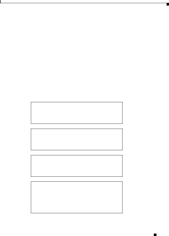
Both models of the PA-2FE (PA-2FE-TX and PA-2FE-FX) are shown in Figure 1-1 and Figure 1-2.
Figure 1-1 |
PA-2FE-TX—Faceplate View |
|
|
|
|
|
PA-2FE-TX |
|
|
ENABLED LINK0 TX0 |
RX0 |
RX1 |
TX1 |
LINK1 |
|
0 |
1 |
|
|
|
|
|
|
46453 |
Figure 1-2 PA-2FE-FX—Faceplate View
|
|
|
|
|
|
|
|
|
|
LEDDEL |
|
CLASE |
1 |
|
ENABLED |
LINK0 |
TX0 |
RX0 |
0 |
|
|
|
|
1 |
|
|
DE |
|
|
|
|
|
RX |
TX |
|
PRODUCT |
VOYANT |
LED |
|
|
|
|||
|
|
|
|
1 |
|
|
|
|
|
|||||
|
|
|
|
|
|
|
KLASSE |
|
|
|
|
|
|
|
|
|
|
|
|
LED |
MIT |
AVEC |
|
|
|
|
|
|
|
|
|
|
|
1 |
CLASSE |
|
|
|
|
|
|
|
||
|
|
|
|
CLASSPRODUKTPRODUITDE |
PRODUCTO |
|
|
|
|
|||||
|
PA-2FE-FX |
|
|
RX |
TX |
TX1 |
LINK1 |
1 |
RX1 |
||
|
|
|
|
|
|
|
46454 |
PA-2FE-TX and PA-2FE-FX Two-Port Fast Ethernet Port Adapter Installation and Configuration
|
OL-3474-07 |
1-1 |
|
|
|

Chapter 1 Overview
Fast Ethernet Overview
Fast Ethernet Overview
The term Ethernet is commonly used for all carrier sense multiple access collision detect (CSMA/CD) LANs that generally conform to Ethernet specifications, including Fast Ethernet under IEEE 802.3u.
Note 100BASE-TX is intended for Environment A, and 100BASE-FX is intended for Environment B. Both are described in the IEEE 802.3u standard.
IEEE 802.3u is well suited to applications where a local communication medium must carry sporadic, occasionally heavy traffic at peak data rates. Stations on a CSMA/CD LAN can access the network at any time. Before sending data, the station listens to the network to see if it is already in use. If it is in use, the station waits until the network is not in use, then transmits. This process is known as half-duplex operation. A collision occurs when two stations listen for network traffic, hear none, and transmit almost simultaneously. When simultaneous transmission occurs, both transmissions are damaged and the stations must retransmit. The stations detect the collision and use backoff algorithms to determine when they should retransmit.
Both Ethernet and IEEE 802.3u are broadcast networks, which means that all stations see all transmissions. Each station must examine received frames to determine whether it is the intended destination and, if it is, pass the frame to a higher protocol layer for processing.
IEEE 802.3u specifies the following different physical layers for 100BASE-T:
•100BASE-TX—100BASE-T, halfand full-duplex over Category 5 UTP, EIA/TIA–568-compliant cable
•100BASE-FX—100BASE-T, halfand full-duplex over optical fiber
Each physical layer protocol has a name that summarizes its characteristics in the format speed/signaling method/segment length, where speed is the LAN speed in megabits per second (Mbps), signaling method is the signaling method used (either baseband or broadband), and segment length is the maximum length between stations in hundreds of meters. Therefore, 100BASE-T specifies a 100-Mbps, baseband LAN with maximum network segments.
IEEE 802.3u 100BASE-T Specifications
This section provides specifications for IEEE 802.3u 100BASE-T. Table 1-1 provides cabling specifications for 100BASE-TX Fast Ethernet transmission over UTP and foil twisted-pair (FTP), and 100BASE-FX Fast Ethernet over fiber-optic cables. It also summarizes IEEE 802.3u 100BASE-TX and 100BASE-FX physical characteristics. (See Figure 1-3.)
|
|
|
|
Table 1-1 |
Cabling Specifications |
|
|
|
|
|
|
|
|
|
|
|
|
|
|
|
|
Parameter |
|
100BASE-TX |
100BASE-FX (Multimode) |
|
|
|
|
|
|
|
|
||
|
|
|
|
Cable specification |
Category 51 UTP2, 22 to 24 |
62.5/125 multimode optical fiber |
||
|
|
|
|
|
|
AWG |
|
|
|
|
|
|
|
|
|
||
|
|
|
|
Maximum segment length |
100 m |
412 m |
||
|
|
|
|
(half-duplex)3 |
|
|
|
|
|
|
|
|
Maximum segment length |
100 m |
2000 m |
||
|
|
|
|
(full-duplex)3 |
|
|
|
|
|
|
|
PA-2FE-TX and PA-2FE-FX Two-Port Fast Ethernet Port Adapter Installation and Configuration |
|
|
|||
|
|
|
|
|
||||
|
|
|
|
|
|
|
|
|
|
1-2 |
|
|
|
|
|
OL-3474-07 |
|
|
|
|
|
|
|
|
||
Chapter 1 Overview
IEEE 802.3u 100BASE-T Specifications
Table 1-1 |
Cabling Specifications (continued) |
|
|
|
|
|
|
Parameter |
|
100BASE-TX |
100BASE-FX (Multimode) |
|
|
|
|
Maximum network length |
200 m |
272 m |
|
(half-duplex, one repeater)4 |
|
|
|
Data rate |
|
100 Mbps |
100 Mbps |
|
|
|
|
Signaling method |
4B/5B5 block coded, scrambled, |
4B/5B block coded, with NRZI |
|
|
|
with MLT-3 line coding |
line coding |
|
|
|
|
Connector |
|
RJ-45 (ISO/IEC 60603-7:-1990 |
SC-type: dual simplex or single |
|
|
|
duplex for RX and TX |
|
|
|
|
Topology |
|
Star/hub |
Star/hub |
|
|
|
|
1.EIA/TIA-568 or EIA-TIA-568 TSB-36 compliant.
2.Cisco does not supply Category 5 UTP RJ-45 cables. However, they are available commercially.
3.Data Terminal Equipment (DTE to DTE), see Figure 1-3.
4.DTE to Repeater to DTE, see Figure 1-3.
5.4B/5B encoding or block coding, encodes four data bits into a 5-bit transmission sequence.
Figure 1-3 Maximum Segment and Network Lengths—100BASE--FX and 100BASE-TX
Maximum segment length, full duplex
100 m TX
DTE*  DTE
DTE
2000 m FX–multimode
Maximum segment length, full duplex
10,000 m FX–single mode
DTE  DTE
DTE
Maximum segment length, half duplex
100 m TX
DTE  DTE 412 m FX
Maximum network length, half duplex
200 m TX
DTE  R
R  DTE (Repeater)
272 m FX**
**Because repeaters have more delay, total network length is shorter.
31703
*DTE = Data Terminal Equipment
PA-2FE-TX and PA-2FE-FX Two-Port Fast Ethernet Port Adapter Installation and Configuration
|
OL-3474-07 |
1-3 |
|
|
|
Chapter 1 Overview
LEDs
Note PA-2FE-FX uses 62.5/125-micron multimode fiber with an SC connector.
LEDs
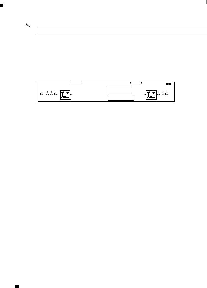
The PA-2FE has seven LEDS; an ENABLED LED, and LINK, TRANSMIT, and RECEIVE LEDs for each port. The LEDs are shown in Figure 1-4.
Figure 1-4 PA-2FE LEDs—Faceplate View of PA-2FE-TX
|
|
|
|
PA-2FE-TX |
|
|
ENABLED |
LINK0 |
TX0 |
RX0 |
RX1 |
TX1 |
LINK1 |
|
|
|
0 |
1 |
|
|
|
|
|
|
|
|
46453 |
After system initialization, the ENABLED LED goes on to indicate that the PA-2FE is ready for operation. The following conditions must be met before the ENABLED LED goes on:
•The PA-2FE is correctly connected and receiving power.
•A PA-2FE–equipped card or chassis contains a valid microcode version that has been successfully downloaded.
•The bus recognizes the PA-2FE.
If any of these conditions are not met, or if the initialization fails for other reasons, the ENABLED LED does not go on. Table 1-2 lists LED colors and indicator functions.
Table 1-2 |
PA-2FE LEDs |
|
|
|
|
|
|
LED Label |
Color |
State |
Function |
|
|
|
|
ENABLED |
Green |
On |
Port adapter is enabled for operation. |
|
|
|
|
LINK0 |
Green |
On |
Port 0 is receiving a carrier signal from the network.1 |
TX0 |
Green |
On |
Port 0 is transmitting data. |
|
|
|
|
RX0 |
Green |
On |
Port 0 is receiving data. |
|
|
|
|
RX1 |
Green |
On |
Port 1 is receiving data. |
|
|
|
|
TX1 |
Green |
On |
Port 1 is transmitting data. |
|
|
|
|
LINK1 |
Green |
On |
Port 1 is receiving a carrier signal from the network.1 |
1. When an RJ-45 or SC port is active.
Receptacles, Cables, and Pinouts
The two interface receptacles on the PA-2FE are a single RJ-45 connection (on the PA-2FE-TX) or an SC-type optical-fiber connection (on the PA-2FE-FX). Each connection supports IEEE 802.3u interfaces compliant with the 100BASE-X and 10/100BASE-T standards. The RJ-45 connection does not require an external transceiver.
PA-2FE-TX and PA-2FE-FX Two-Port Fast Ethernet Port Adapter Installation and Configuration
1-4 |
OL-3474-07 |
|
|
Chapter 1 Overview
Receptacles, Cables, and Pinouts
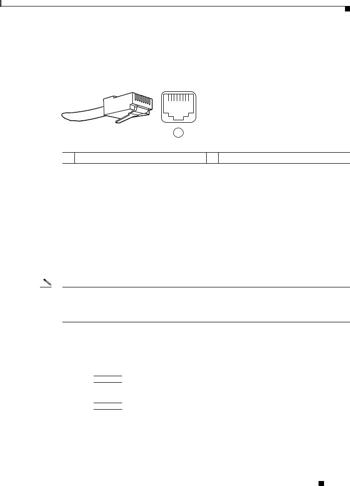
Figure 1-5 shows the RJ-45 cable connectors. Cisco does not supply Category 5 UTP RJ-45 cables; they are available from a commercial supplier. Table 1-3 lists the pinouts and signals for the PA-2FE-TX RJ-45 connectors.
Figure 1-5 RJ-45 Port and Connector
12345678
1
1 RJ-45 connector and port
84529
Table 1-3 |
IRJ-45 Port Pinout Information |
|
|
Pin |
Description |
|
|
1 |
TxD+1 |
2 |
TxD– |
|
|
3 |
RxD+2 |
6 |
RxD– |
|
|
1.TxD = Transmit data
2.RxD = Receive data
Note Referring to the RJ-45 pinout in Table 1-3, proper common-mode line terminations should be used for the unused Category 5, UTP cable pairs 4/5 and 7/8. Common-mode line termination reduces the contributions to electromagnetic interference (EMI) and susceptibility to common-mode sources. Wire pairs 4/5 and 7/8 are passively terminated in the RJ-45 100BASE-TX port circuitry in the PA-2FE-TX.
Depending on your RJ-45 interface cabling requirements, use the pinouts in Figure 1-6 and Figure 1-7.
Figure 1-6
Ethernet port
1TxD+
2TxD–
3RxD+
6RxD–
Straight-Through Cable Pinout—PA-2FE-TX RJ-45 Connection to a Hub or Repeater
Hub
1 RxD+
2 RxD–
6 TxD– |
38582 |
3 TxD+ |
|
PA-2FE-TX and PA-2FE-FX Two-Port Fast Ethernet Port Adapter Installation and Configuration
|
OL-3474-07 |
1-5 |
|
|
|
Chapter 1 Overview
Network Management
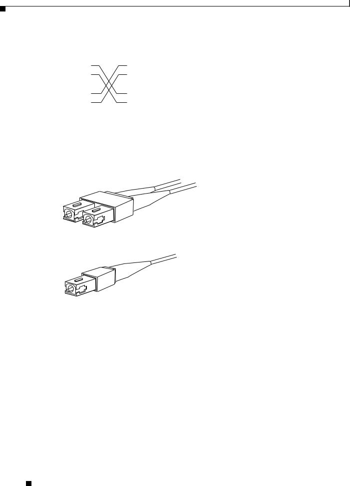
Figure 1-7
Ethernet port
1TxD+
2TxD–
3RxD+
6RxD–
Crossover Cable Pinout—PA-2FE-TX RJ-45 Connections Between Hubs and Repeaters
DTE
1 TxD+
2 TxD–
3 RxD+ |
38583 |
6 RxD– |
Figure 1-8 shows the duplex SC connector (one required for both transmit and receive), and Figure 1-9 shows the simplex SC connector (two required, one each for transmit and receive) used for PA-2FE-FX optical-fiber connections. Cisco does not supply these multimode optical-fiber cables; they are available from a commercial supplier.
Figure 1-8 PA-2FE-FX Duplex SC Connector
H2214
Figure 1-9 PA-2FE-FX Simplex SC Connector
H2399
Network Management
The PA-2FE supports the following:
•SNMP agent v1 (RFC 1155–1157)
•Ethernet MIB (RFC 1398)
•IEEE 802.3 LAN specification for CSMA/CD
•MIB for Network Management of TCP/IP-Based Internets: MIB-II (RFC 1213)
•Definition of Managed Objects for Bridges (RFC 1493)
•Evolution of Interfaces Group of MIB-II (RFC 1573)
PA-2FE-TX and PA-2FE-FX Two-Port Fast Ethernet Port Adapter Installation and Configuration
1-6 |
OL-3474-07 |
|
|
Chapter 1 Overview
Port Adapter Slot Locations on the Supported Platforms
Port Adapter Slot Locations on the Supported Platforms
This section discusses port adapter slot locations on the supported platforms. The illustrations that follow summarize slot location conventions on each platform:
•Cisco 7100 Series Routers Slot Numbering, page 1-7
•Cisco 7200 Series Routers and Cisco 7200 VXR Routers Slot Numbering, page 1-8
•Cisco uBR7200 Series Router Slot Numbering, page 1-9
•Cisco 7201 Router Slot Numbering, page 1-10
•Cisco 7301 Router Slot Numbering, page 1-10
•Cisco 7304 PCI Port Adapter Carrier Card Slot Numbering, page 1-11
•Cisco 7401ASR Router Slot Numbering, page 1-12
•Cisco 7500 Series Routers with VIP Slot Numbering, page 1-12
Note The port adapters shown in the slot identification illustrations may not be the same port adapter that is documented in this guide.
Cisco 7100 Series Routers Slot Numbering
The PA-2FE can be installed in port adapter slot 3 in Cisco 7120 series routers, and in port adapter slot 4 in Cisco 7140 series routers. Figure 1-10 shows the slot numbering on a Cisco 7120 series router. Figure 1-11 shows the slot numbering on a Cisco 7140 series router.
Figure 1-10 Port Adapter Slots in the Cisco 7120 Series Router
|
|
|
|
Slot 5 |
Slot 3 |
|
|
|
Slot 4 |
|
|
|
|
|
|
|
|
|
|
|
|
SLOT 0 |
SLOT 1 |
|
|
|
|
|
|
|
|
|
|
ACT ACT |
|
|
|
PWR |
5 |
|
|
|
|
|
|
|
|
|
|
|
0 |
|
|
|
|
|
|
|
LNK LNK |
|
|
|
SYS |
|
|
|
|
|
|
|
|
|
|
CONS |
AUX |
||
|
|
|
TX |
RX |
FE 0 / 0 |
FE |
0 / 1 |
0 1 |
|
RDY |
||
I |
|
E3 |
|
|
|
|
|
|
|
|
||
EN |
RX |
|
|
|
|
|
|
|
|
|
2 |
|
|
|
|
|
|
|
|
|
|
|
|
|
|
|
|
CEL CAR ALM |
|
|
|
|
|
|
|
|
7120 - AE3 |
|
|
|
|
|
|
|
|
|
|
|
|
||
Slot 1 |
Slot 0 |
Slot 2 |
18498
PA-2FE-TX and PA-2FE-FX Two-Port Fast Ethernet Port Adapter Installation and Configuration
|
OL-3474-07 |
1-7 |
|
|
|
Chapter 1 Overview
Port Adapter Slot Locations on the Supported Platforms
Figure 1-11 Port Adapter Slots in the Cisco 7140 Series Router
Slot 5 |
Slot 3 |
Slot 4 |
|
|
|
|
|
|
|
|
|
|
|
|
|
|
|
AC OK |
|
|
|
|
|
|
|
|
|
|
|
|
|
|
|
|
DC OK |
|
|
|
|
|
|
|
|
|
|
|
|
|
|
|
|
OTF |
|
|
|
|
|
BOOT |
|
|
|
|
|
SLOT 0 |
SLOT 1 |
|
|
|
|
|
|
|
|
|
|
|
|
|
|
|
|
|
|
|
|
|
|
|
|
SM-ISM |
RESET |
ERROR |
|
|
|
ACT |
ACT |
|
|
|
PWR |
|
|
|
5 |
|
|
|
EN |
|
|
|
|
|
|
|
|
|
0 |
|
|
|
|
|
|
|
|
|
|
|
|
|
|
|
|
|
||
|
|
|
|
|
|
|
|
LNK |
LNK |
|
|
|
SYS |
|
AC OK |
|
|
|
|
|
FE |
0 / 0 |
FE |
0 / 1 |
0 |
1 |
|
CONS |
AUX |
RDY |
|
DC OK |
|
|
|
RX 155 - MM TX |
|
|
|
|
|
|
155 - MM |
TX |
|
|
|
|
OTF |
18499 |
I |
|
|
|
|
|
|
|
RX |
|
|
|
|
|
|||
EN |
RX |
|
EN |
|
RX |
|
|
|
|
|
|
|
2 |
|
||
|
|
|
|
|
|
|
|
|
|
|
|
|
|
|
|
|
|
|
CEL CAR ALM |
|
|
CEL CAR ALM |
|
|
|
|
7140 - 2MM3 |
|
|
|
|||
|
|
|
|
|
|
|
|
|
|
|
|
|
|
|
||
Slot 1 |
Slot 0 |
Slot 2 |
Cisco 7200 Series Routers and Cisco 7200 VXR Routers Slot Numbering
Cisco 7202 routers have two port adapter slots. The slots are numbered from left to right. You can place the port adapters in either of the slots (slot 1 or slot 2). The Cisco 7202 router is not shown.
Cisco 7204 routers and Cisco 7204VXR routers have four slots for port adapters, and one slot for an input/output (I/O) controller. The slots are numbered from the lower left to the upper right, beginning with slot 1 and continuing through slot 4.You can place the port adapters in any of the slots (slot 1 through slot 4). Slot 0 is always reserved for the I/O controller. The Cisco 7204 router and Cisco 7204VXR are not shown
Cisco 7206 routers and Cisco 7206VXR routers have six slots for port adapters, and one slot for an input/output (I/O) controller. The slots are numbered from the lower left to the upper right, beginning with slot 1 and continuing through slot 6. You can place the port adapters in any of the six slots (slot 1 through slot 6). Slot 0 is always reserved for the I/O controller. Figure 1-12 shows the slot numbering on a Cisco 7206 router. The Cisco 7206VXR router is not shown.
Figure 1-12 Port Adapter Slots in the Cisco 7206 Router
3
EN 1
Cisco 7200
Series
ENABLED
|
|
|
|
|
|
|
|
|
ETHERNET 10BT |
|
|
|
|
D |
|
|
|
|
|
|
|
|
|
|
|
|
|
FAST ETHERNET |
|
||
|
|
|
|
|
|
|
|
|
|
|
|
L E |
|
|
|
|
|
|
|
|
|
K |
|
J45 |
|
|
|
|
4 |
||
|
|
|
|
|
|
|
|
|
|
|
|
A B |
|
|
|
|
|
|
M |
II |
|
IN |
R |
|
|
|
|
||||
|
|
|
|
|
|
|
|
|
|
E |
N |
|
|
|
|
|
|
|
L |
|
|
|
|
|
|||||||
|
|
|
|
|
|
|
|
|
|
|
|
|
|
|
|
|
|
|
|
|
|
|
|
|
|
|
|||||
|
|
|
|
|
|
|
|
|
|
|
|
|
|
|
|
|
|
|
|
0 |
|
|
|
|
|
|
|
|
|
|
|
|
|
|
|
|
|
|
|
SERIAL-V.35 |
|
|
|
|
|
|
|
|
|
|
|
|
|
|
|
|
|
|
ETHERNET-10BFL |
|
|
||
|
|
|
|
|
|
|
|
EN |
|
|
|
|
|
|
|
|
|
RX |
|
|
|
TX |
|
RX |
TX |
R |
X |
TX |
2 |
||
0 |
1 |
2 |
3 |
4 |
5 |
6 |
|
7 |
|
|
|
|
|
RX |
|
|
TX |
RX |
TX |
|
|
|
|
4 |
|||||||
|
|
|
|
|
|
|
0 |
|
|
|
1 |
2 |
|
|
|
|
|
|
3 |
|
|
|
|||||||||
|
|
|
|
|
|
SLOT |
1 |
FE |
MII |
|
|
|
|
|
|
|
|
RJ |
|
|
|
FAST ETHERNET INPUT/OUTPUT CONTROLLER |
|
|
|||||||
|
|
|
|
|
|
|
|
|
|
|
|
|
|
|
|
|
-45 |
|
|
|
|
|
|
|
|
|
|
|
|
|
|
|
|
|
|
|
|
|
|
|
|
|
|
|
|
|
|
|
|
|
|
|
|
|
|
|
|
|
|
|
|
|
0 |
|
|
|
|
|
|
0 |
|
|
|
MII |
|
RJ |
|
RJ |
|
PWR |
|
|
|
|
|
|
|
|
|
|
|
|
|
||
|
|
|
|
|
|
|
|
|
|
|
|
|
-45 |
-45 |
|
|
|
|
|
|
|
|
|
|
|
|
|
|
|
||
|
PCMCIA |
|
|
EJECT |
SLOT |
|
|
|
|
EN |
|
|
|
EN |
|
LINK |
1O |
OK |
|
|
|
|
|
|
|
|
|
|
|
|
|
|
|
|
|
|
|
|
|
|
|
|
|
|
|
|
|
|
|
|
|
|
|
|
|
|
|
|
|
|
|||
28329
Port adapter slot 5 |
Port adapter slot 6 |
Port adapter slot 3 |
Port adapter slot 4 |
Port adapter slot 1 |
Port adapter slot 2 |
|
Port adapter slot 0 |
PA-2FE-TX and PA-2FE-FX Two-Port Fast Ethernet Port Adapter Installation and Configuration
1-8 |
OL-3474-07 |
|
|
Chapter 1 Overview
Port Adapter Slot Locations on the Supported Platforms
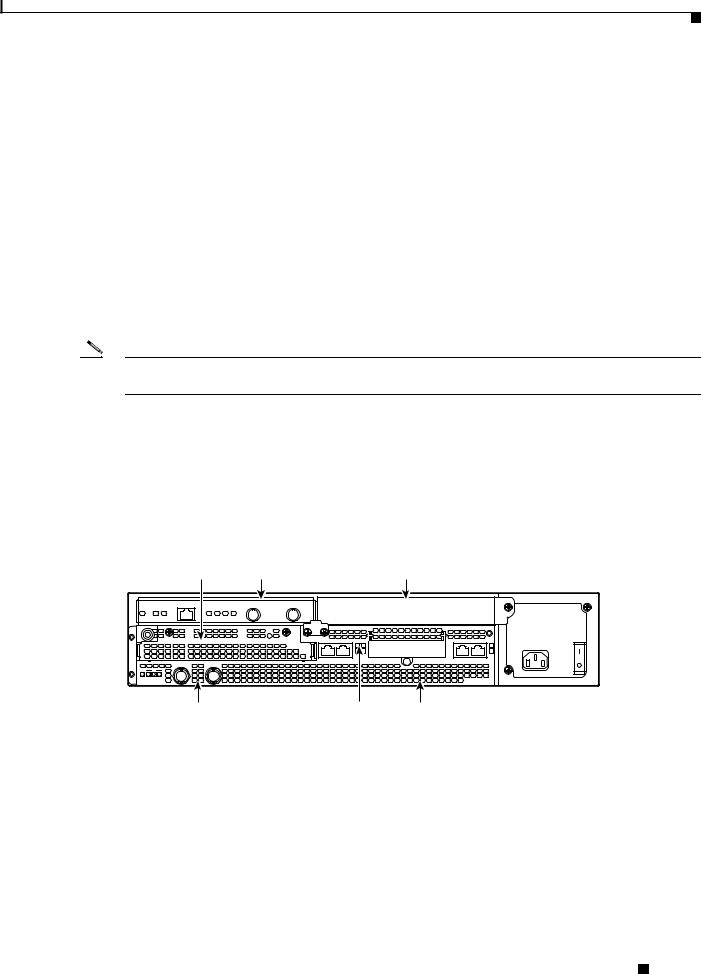
Cisco uBR7200 Series Router Slot Numbering
The Cisco uBR7223 router has one port adapter slot (slot 1). Slot 0 is always reserved for the I/O controller—if present. The Cisco uBR7223 router is not shown.
The Cisco uBR7246 router and Cisco uBR7246VXR router have two port adapter slots (slot1 and slot 2). Slot 0 is always reserved for the I/O controller—if present. Figure 1-13 shows the slot numbering of port adapters on a Cisco uBR7246VXR router. The Cisco uBR7246 router is not shown.
Figure 1-13 Port Adapter Slots in the Cisco uBR7246VXR Router
Port adapter slot 0 |
|
Port adapter slot 1 |
|
Port adapter slot 2 |
||||||
|
|
|||||||||
(I/O controller) |
|
(blank) |
|
|
|
|||||
|
|
|
|
|
|
|
|
|
|
|
|
|
|
|
|
|
|
|
|
|
|
|
|
|
|
|
|
|
|
|
|
|
|
|
|
|
|
|
|
|
|
|
|
|
|
|
|
|
|
|
|
|
|
|
ENABLED ENABLED ENABLED ENABLED
US
US
US
US
|
|
|
|
|
|
3 |
|
4 |
US |
5 |
uBR - MCI6 |
0 |
US |
1 |
US |
2 |
US |
|
US |
|
|
DS |
|
|
|
|
|
|
|
||||||
|
|
|
|
2 |
|
|
|
|
US |
5 |
uBR - MCI6 |
0 |
US |
1 |
US |
|
|
|
|
|
DS |
||
|
|
|
|
2 |
|
|
|
|
US |
5 |
uBR - MCI6 |
0 |
US |
1 |
US |
|
|
|
|
|
DS |
||
|
|
|
|
2 |
|
|
|
|
US |
5 |
uBR - MCI6 |
0 |
US |
1 |
US |
|
|
|
|
|
DS |
||
|
|
|
Cable modem card slot 3 |
||||||||
|
|
|
Cable modem card slot 4 |
||||||||
|
|
|
Cable modem card slot 5 |
||||||||
|
|
|
Cable modem card slot 6 |
||||||||
H11323
PA-2FE-TX and PA-2FE-FX Two-Port Fast Ethernet Port Adapter Installation and Configuration
|
OL-3474-07 |
1-9 |
|
|
|
Chapter 1 Overview
Port Adapter Slot Locations on the Supported Platforms
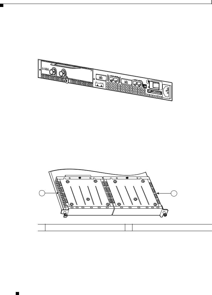
Cisco 7201 Router Slot Numbering
Figure 1-14 shows the front view of a Cisco 7201 router with a port adapter installed. There is only one port adapter slot (slot 1) in a Cisco 7201 router.
Figure 1-14 Port Adapter Slot in the Cisco 7201 Router
Port adapter slot
ENABLED |
RX |
CELLS |
CARRIERALARM |
|
RX |
RX |
ATM
RJ45 |
|
Cisco 7201 |
|
|
|
|
|
|
|
|
|
EN |
LINK/ACTV |
|
|
|
|
|
|
CONSOLE |
|
|
|
|
|
SFP |
RJ45 EN |
LINK/ACTV |
|
|
|
|
|
||
|
|
|
LINK/ACTV |
|
|
|
|
|
|||
|
|
|
TX |
SFP |
RX |
|
LINK/ACTV |
|
|
||
PA |
|
|
|
|
|
SFP |
TX |
|
|
||
|
|
|
|
|
|
SFP |
RX |
|
|
||
SLOT 1 |
|
GE |
|
|
|
|
|
|
MNGMNT |
|
|
|
|
0/0 |
|
|
|
|
|
|
|
|
|
|
|
|
GE 0/1 |
|
|
|
|
|
USE ONLY |
|
|
|
|
|
|
|
|
|
|
|
|
|
|
|
|
|
|
|
|
GE 0/2 |
|
GE 0/3 |
|
|
|
|
|
|
|
|
|
|
|
AUX |
|
|
|
|
|
|
|
|
|
|
|
|
|
|
|
|
|
|
|
|
|
|
|
|
FE 0/0 |
FE |
0 |
|
|
|
|
|
|
|
|
|
|
LINK |
|
COMPACT FLASH
ALARM PWR OK

 STATUS
CF ACTV
 230308
Cisco 7301 Router Slot Numbering
Figure 1-15 shows the front view of a Cisco 7301 router with a port adapter installed. There is only one port adapter slot (slot 1) in a Cisco 7301 router.
Figure 1-15 Port Adapter Slot in the Cisco 7301 Router
Port adapter slot
ENABLED
RX |
CELLS |
CARRIERALARM |
RX |
RX |
ATM 
SLOT 1 |
RJ45 |
GIGABIT ETHERNET 0/0 |
|
|
|
|
|
|
|
|
|
|
|
|
EN |
|
|
GIGABIT |
ETHERNET 0/1 |
|
|
|
|
|
|
|
|
LINK |
|
RJ45 EN |
|
|
|
|
|
|||
|
|
TX |
GBIC |
RX |
LINK |
|
GIGABIT ETHERNET 0/2 |
|
|
|||
|
|
|
|
|
|
TX |
GBIC |
RX |
RJ45 EN |
|
AUX |
|
|
|
|
|
|
|
|
|
LINK |
CONSOLE |
|||
|
|
|
|
|
|
|
|
|
TX |
GBIC |
RX |
|
|
|
|
|
|
|
|
|
|
|
|
||
CISCO 7400SERIES
CISCO 7411
100-240V, |
|
24V |
=9A, |
ALARM |
|
COMPACT |
|
FLASH |
STATUS |
2A, 48 -
50/60 Hz 60V=5A
84988
PA-2FE-TX and PA-2FE-FX Two-Port Fast Ethernet Port Adapter Installation and Configuration
1-10 |
OL-3474-07 |
|
|

Chapter 1 Overview
Port Adapter Slot Locations on the Supported Platforms
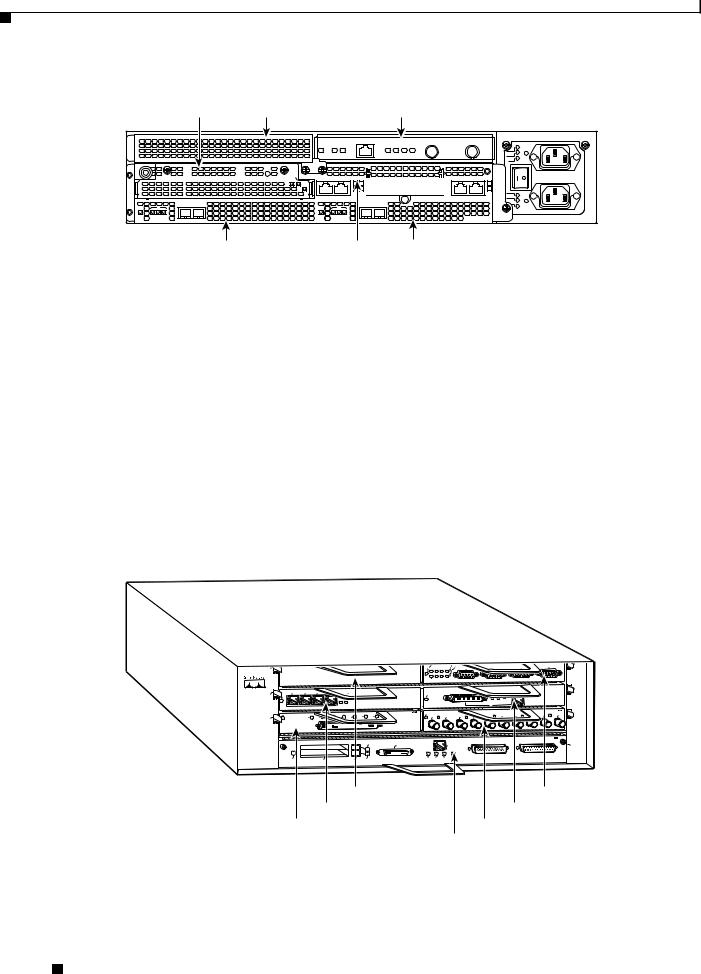
Cisco 7304 PCI Port Adapter Carrier Card Slot Numbering
The Cisco 7304 PCI port adapter carrier card installs into Cisco 7304 router module slots 2 through 5. Figure 1-16 shows the module slot numbering on a Cisco 7304 router. The port adapter slot number is the same as the module slot number. Slot 0 and slot 1 are reserved for the NPE module or NSE module.
Figure 1-16
Slot 4
OIR |
|
STATUS |
|
1- |
|
PORT OC48 |
POS w/ |
|
SMSR |
Slot 0
Module Slots on the Cisco 7304 Router
Slot 5
TX
RX
9K- |
|
|
|
40C3/POS-MM |
|
||
|
OIR |
|
|
STATUS |
|
1 |
|
|
|
|
0 |
4-PORT |
OC3 POS |
w/ MM |
2 |
|
3 |
||
|
|
|
|
|
|
|
CARRIER/ |
|
|
|
ALARM |
ACTIVE/
LOOPBACK
Slot 2
70550
Slot 3  Slot 1
The Cisco 7304 PCI port adapter carrier card accepts one single-width port adapter. Figure 1-17 shows a Cisco 7304 PCI port adapter carrier card with a port adapter installed.
Figure 1-17 Cisco 7304 PCI Port Adapter Carrier Card—Port Adapter Installed
7300-CC-PA
OIR 
STATUS
7300 PA CARRIER
ENABLED
RX |
CELLS |
CARRIERALARM |
RX |
RX |
ATM 

84653
PA-2FE-TX and PA-2FE-FX Two-Port Fast Ethernet Port Adapter Installation and Configuration
|
OL-3474-07 |
1-11 |
|
|
|
Chapter 1 Overview
Port Adapter Slot Locations on the Supported Platforms
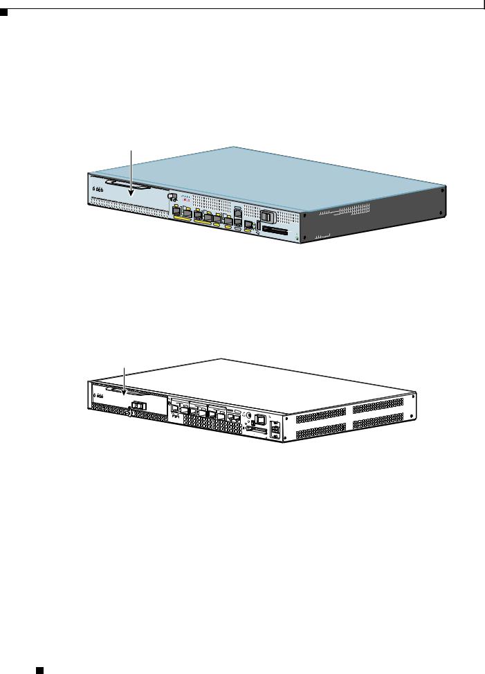
Cisco 7401ASR Router Slot Numbering
Figure 1-18 shows the front view of a Cisco 7401ASR router with a port adapter installed. There is only one port adapter slot (slot 1) in a Cisco 7401ASR router.
Figure 1-18 Port Adapter Slot in the Cisco 7401ASR Router
ENABLED
RX |
CELLS |
CARRIERALARM |
RX |
RX |
 TX
TX  RX
RX
ENHANCED ATM 
57680
Cisco 7500 Series Routers with VIP Slot Numbering
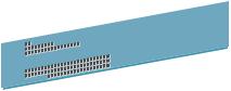
The PA-2FE is supported on theVIP2, VIP4, VIP6-80 versatile interface processors used in Cisco 7500 series routers. In the Cisco 7505 router, the VIP motherboard is installed horizontally in the VIP slot. In the Cisco 7507 router and Cisco 7513 router, the VIP motherboard is installed vertically in the VIP slot. The port adapter can be installed in either bay (port adapter slot 0 or 1) on the VIP. The bays are numbered from left to right on the VIP. Figure 1-19 shows the slot numbering on a VIP.
Figure 1-19 VIP Slot Locations
1 |
2 |
|
129720 |
1 VIP port adapter slot 0 |
2 VIP port adapter slot 1 |
PA-2FE-TX and PA-2FE-FX Two-Port Fast Ethernet Port Adapter Installation and Configuration
1-12 |
OL-3474-07 |
|
|
Chapter 1 Overview
Port Adapter Slot Locations on the Supported Platforms
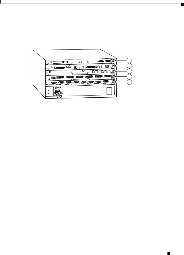
Cisco 7505 routers have four slots for port adapters, and one slot for a Route Switch Processor (RSP). The slots are numbered from bottom to top. You can place the port adapters in any of the VIP interface slots (slot 0 through 3). One slot is always reserved for the RSP. Figure 1-20 shows the slot numbering on a Cisco 7505 router.
Figure 1-20 VIP Slots in the Cisco 7505 Router
|
|
|
|
|
|
|
|
|
|
T |
|
|
ROUTE SWITCH PROCESSOR |
||
|
|
|
|
C |
T |
|
1 |
|
U |
HAL |
ET |
|
|
|
|
|
|
|
EJE |
|
OT |
CP |
RE |
S |
|
|
|
LE |
|||
|
|
L |
|
SL |
0 |
|
|
. |
|
|
|||||
|
RM |
A |
|
|
LOT |
|
|
|
AU |
X |
|
ONS |
O |
||
NO |
|
|
|
S |
|
|
|
|
|
C |
|
||||
|
|
|
|
|
|
|
|
|
|
|
|
|
|||
|
|
|
E |
|
LE |
|
BL |
EN |
AB |
EN |
|
|
|
|
122193
1
2
3
4
5
1 |
RSP |
4 |
VIP interface—slot 1 |
|
|
|
|
2 |
VIP interface—slot 3 |
5 |
VIP interface—slot 0 |
|
|
|
|
3 |
VIP interface—slot 2 |
|
|
|
|
|
|
PA-2FE-TX and PA-2FE-FX Two-Port Fast Ethernet Port Adapter Installation and Configuration
|
OL-3474-07 |
1-13 |
|
|
|
Loading...