


OPERATION AND SERVICE MANUAL
INTEGRA 30S
TRUCK REFRIGERATION UNIT BEGINNING WITH S/N PB 225225
|
|
TABLE OF CONTENTS |
|
PARAGRAPH NUMBER |
Page |
||
GENERAL SAFETY NOTICES . . . . . . . . . . . . . . . . . . . . . . . . . . . . . . . . . . . . . . . . . . . . . . . . . . . . . . . . . . . . |
Safety-1 |
||
FIRST AID . . . . . . . . . . . . . . . . . . . . . . . . . . . . . . . . . . . . . . . . . . . . . . . . . . . . . . . . . . . . . . . . . . . . . . . . . . . . . |
Safety-1 |
||
OPERATING PRECAUTIONS . . . . . . . . . . . . . . . . . . . . . . . . . . . . . . . . . . . . . . . . . . . . . . . . . . . . . . . . . . . . |
Safety-1 |
||
MAINTENANCE PRECAUTIONS . . . . . . . . . . . . . . . . . . . . . . . . . . . . . . . . . . . . . . . . . . . . . . . . . . . . . . . . . . |
Safety-1 |
||
SPECIFIC WARNING AND CAUTION STATEMENTS . . . . . . . . . . . . . . . . . . . . . . . . . . . . . . . . . . . . . . . . |
Safety-1 |
||
DESCRIPTION . . . . . . . . . . . . . . . . . . . . . . . . . . . . . . . . . . . . . . . . . . . . . . . . . . . . . . . . . . . . . . . . . . . . . . . . . . . . . |
. . 1-1 |
||
1.1 |
INTRODUCTION . . . . . . . . . . . . . . . . . . . . . . . . . . . . . . . . . . . . . . . . . . . . . . . . . . . . . . . . . . . . . . . . . . . . |
. 1-1 |
|
1.2 |
GENERAL DESCRIPTION . . . . . . . . . . . . . . . . . . . . . . . . . . . . . . . . . . . . . . . . . . . . . . . . . . . . . . . . . . . . |
. 1-1 |
|
1.3 |
CONDENSING SECTION . . . . . . . . . . . . . . . . . . . . . . . . . . . . . . . . . . . . . . . . . . . . . . . . . . . . . . . . . . . . |
. 1-1 |
|
|
1.3.1 |
Condenser/Subcooler . . . . . . . . . . . . . . . . . . . . . . . . . . . . . . . . . . . . . . . . . . . . . . . . . . . . . . . . . . . . . |
. 1-1 |
|
1.3.2 |
Filter Drier . . . . . . . . . . . . . . . . . . . . . . . . . . . . . . . . . . . . . . . . . . . . . . . . . . . . . . . . . . . . . . . . . . . . . . . |
. 1-1 |
|
1.3.3 |
Oil Separator . . . . . . . . . . . . . . . . . . . . . . . . . . . . . . . . . . . . . . . . . . . . . . . . . . . . . . . . . . . . . . . . . . . . |
. 1-3 |
|
1.3.4 |
Hot Gas Solenoid Valve (HGS1) . . . . . . . . . . . . . . . . . . . . . . . . . . . . . . . . . . . . . . . . . . . . . . . . . . . . |
. 1-3 |
|
1.3.5 |
Condenser Pressure Control Valve (HGS2) . . . . . . . . . . . . . . . . . . . . . . . . . . . . . . . . . . . . . . . . . . |
. 1-3 |
|
1.3.6 |
Compressor . . . . . . . . . . . . . . . . . . . . . . . . . . . . . . . . . . . . . . . . . . . . . . . . . . . . . . . . . . . . . . . . . . . . . |
. 1-3 |
|
1.3.7 |
Standby Motor . . . . . . . . . . . . . . . . . . . . . . . . . . . . . . . . . . . . . . . . . . . . . . . . . . . . . . . . . . . . . . . . . . . |
. 1-3 |
|
1.3.8 |
Receiver . . . . . . . . . . . . . . . . . . . . . . . . . . . . . . . . . . . . . . . . . . . . . . . . . . . . . . . . . . . . . . . . . . . . . . . . |
. 1-3 |
|
1.3.9 |
High Pressure Switch (HP1) . . . . . . . . . . . . . . . . . . . . . . . . . . . . . . . . . . . . . . . . . . . . . . . . . . . . . . . |
. 1-4 |
|
1.3.10 Condenser Pressure Control Switch (HP2) . . . . . . . . . . . . . . . . . . . . . . . . . . . . . . . . . . . . . . . . . . . |
. 1-4 |
|
1.4 |
EVAPORATOR SECTION . . . . . . . . . . . . . . . . . . . . . . . . . . . . . . . . . . . . . . . . . . . . . . . . . . . . . . . . . . . . |
. 1-4 |
|
|
1.4.1 |
Thermostatic Expansion Valve . . . . . . . . . . . . . . . . . . . . . . . . . . . . . . . . . . . . . . . . . . . . . . . . . . . . . |
. 1-4 |
|
1.4.2 Compressor Pressure Regulating Valve (CPR) (115V Only) . . . . . . . . . . . . . . . . . . . . . . . . . . . . |
. 1-4 |
|
|
1.4.3 Defrost Termination Thermostat (DTT) . . . . . . . . . . . . . . . . . . . . . . . . . . . . . . . . . . . . . . . . . . . . . . |
. 1-4 |
|
|
1.4.4 |
Quench Valve (BPV) . . . . . . . . . . . . . . . . . . . . . . . . . . . . . . . . . . . . . . . . . . . . . . . . . . . . . . . . . . . . . . |
. 1-4 |
|
1.4.5 |
Evaporator . . . . . . . . . . . . . . . . . . . . . . . . . . . . . . . . . . . . . . . . . . . . . . . . . . . . . . . . . . . . . . . . . . . . . . |
. 1-4 |
|
1.4.6 Low Pressure Switch (LP) . . . . . . . . . . . . . . . . . . . . . . . . . . . . . . . . . . . . . . . . . . . . . . . . . . . . . . . . . |
. 1-4 |
|
1.5 SYSTEM OPERATING CONTROLS AND COMPONENTS . . . . . . . . . . . . . . . . . . . . . . . . . . . . . . . . |
. 1-8 |
||
1.6 |
UNIT SPECIFICATIONS . . . . . . . . . . . . . . . . . . . . . . . . . . . . . . . . . . . . . . . . . . . . . . . . . . . . . . . . . . . . . . |
. 1-9 |
|
|
1.6.1 |
Compressor Data . . . . . . . . . . . . . . . . . . . . . . . . . . . . . . . . . . . . . . . . . . . . . . . . . . . . . . . . . . . . . . . . |
. 1-9 |
|
1.6.2 |
Refrigeration System Data . . . . . . . . . . . . . . . . . . . . . . . . . . . . . . . . . . . . . . . . . . . . . . . . . . . . . . . . . |
. 1-9 |
|
1.6.3 |
Electrical Data . . . . . . . . . . . . . . . . . . . . . . . . . . . . . . . . . . . . . . . . . . . . . . . . . . . . . . . . . . . . . . . . . . . |
. 1-10 |
|
1.6.4 |
Torque Values . . . . . . . . . . . . . . . . . . . . . . . . . . . . . . . . . . . . . . . . . . . . . . . . . . . . . . . . . . . . . . . . . . . |
. 1-10 |
1.7 |
SAFETY DEVICES . . . . . . . . . . . . . . . . . . . . . . . . . . . . . . . . . . . . . . . . . . . . . . . . . . . . . . . . . . . . . . . . . . |
. 1-11 |
|
1.8 |
REFRIGERANT Circuit . . . . . . . . . . . . . . . . . . . . . . . . . . . . . . . . . . . . . . . . . . . . . . . . . . . . . . . . . . . . . . . |
. 1-12 |
|
|
1.8.1 |
Cooling . . . . . . . . . . . . . . . . . . . . . . . . . . . . . . . . . . . . . . . . . . . . . . . . . . . . . . . . . . . . . . . . . . . . . . . . . |
. 1-12 |
|
1.8.2 |
Heat And Defrost . . . . . . . . . . . . . . . . . . . . . . . . . . . . . . . . . . . . . . . . . . . . . . . . . . . . . . . . . . . . . . . . . |
. 1-12 |
i |
62--10848 |
TABLE OF CONTENTS (Continued)
PARAGRAPH NUMBER |
Page |
||
OPERATION |
. . . . . . . . . . . . . . . . . . . . . . . . . . . . . . . . . . . . . . . . . . . . . . . . . . . . . . . . . . . . . . . . . . . . . . . . . . . . . . . . . |
2-1 |
|
2.1 |
CONTROL SYSTEM . . . . . . . . . . . . . . . . . . . . . . . . . . . . . . . . . . . . . . . . . . . . . . . . . . . . . . . . . . . . . . . . . . |
2-1 |
|
|
2.1.1 |
Introduction . . . . . . . . . . . . . . . . . . . . . . . . . . . . . . . . . . . . . . . . . . . . . . . . . . . . . . . . . . . . . . . . . . . . . . |
2-1 |
|
1.8.3 |
Microprocessor Module . . . . . . . . . . . . . . . . . . . . . . . . . . . . . . . . . . . . . . . . . . . . . . . . . . . . . . . . . . . . |
2-1 |
|
2.1.2 |
Cab Command . . . . . . . . . . . . . . . . . . . . . . . . . . . . . . . . . . . . . . . . . . . . . . . . . . . . . . . . . . . . . . . . . . . . |
2-1 |
2.2 |
START--UP . . . . . . . . . . . . . . . . . . . . . . . . . . . . . . . . . . . . . . . . . . . . . . . . . . . . . . . . . . . . . . . . . . . . . . . . . . |
2-2 |
|
|
2.2.1 |
Inspection . . . . . . . . . . . . . . . . . . . . . . . . . . . . . . . . . . . . . . . . . . . . . . . . . . . . . . . . . . . . . . . . . . . . . . . . |
2-2 |
|
2.2.2 |
Connect Power . . . . . . . . . . . . . . . . . . . . . . . . . . . . . . . . . . . . . . . . . . . . . . . . . . . . . . . . . . . . . . . . . . . |
2-3 |
|
2.2.3 |
Starting . . . . . . . . . . . . . . . . . . . . . . . . . . . . . . . . . . . . . . . . . . . . . . . . . . . . . . . . . . . . . . . . . . . . . . . . . . |
2-3 |
2.3 |
SETPOINT ADJUSTMENT . . . . . . . . . . . . . . . . . . . . . . . . . . . . . . . . . . . . . . . . . . . . . . . . . . . . . . . . . . . . |
2-3 |
|
2.4 |
MANUAL DEFROST . . . . . . . . . . . . . . . . . . . . . . . . . . . . . . . . . . . . . . . . . . . . . . . . . . . . . . . . . . . . . . . . . . |
2-3 |
|
2.5 |
DEFROST CYCLE ADJUSTMENT . . . . . . . . . . . . . . . . . . . . . . . . . . . . . . . . . . . . . . . . . . . . . . . . . . . . . . |
2-3 |
|
2.6 |
ALARM DISPLAY . . . . . . . . . . . . . . . . . . . . . . . . . . . . . . . . . . . . . . . . . . . . . . . . . . . . . . . . . . . . . . . . . . . . . |
2-4 |
|
|
2.6.1 |
Accessing Alarm Messages . . . . . . . . . . . . . . . . . . . . . . . . . . . . . . . . . . . . . . . . . . . . . . . . . . . . . . . . |
2-4 |
|
2.6.2 Low Battery Voltage Alarm for Road Only Units . . . . . . . . . . . . . . . . . . . . . . . . . . . . . . . . . . . . . . . |
2-5 |
|
|
2.6.3 |
Clearing Alarm Messages . . . . . . . . . . . . . . . . . . . . . . . . . . . . . . . . . . . . . . . . . . . . . . . . . . . . . . . . . . |
2-5 |
2.7 |
CHECKING THE EEPROM VERSION . . . . . . . . . . . . . . . . . . . . . . . . . . . . . . . . . . . . . . . . . . . . . . . . . . . |
2-5 |
|
2.8 |
STOPPING THE UNIT . . . . . . . . . . . . . . . . . . . . . . . . . . . . . . . . . . . . . . . . . . . . . . . . . . . . . . . . . . . . . . . . |
2-5 |
|
2.9 |
MICROPROCESSOR CONFIGURATION . . . . . . . . . . . . . . . . . . . . . . . . . . . . . . . . . . . . . . . . . . . . . . . . |
2-6 |
|
|
2.9.1 ROAD ONLY FUNCTIONAL SETTINGS . . . . . . . . . . . . . . . . . . . . . . . . . . . . . . . . . . . . . . . . . . . . . |
2-6 |
|
|
2.9.2 |
ROAD/STANDBY FUNCTIONAL SETTINGS . . . . . . . . . . . . . . . . . . . . . . . . . . . . . . . . . . . . . . . . . |
2-7 |
TEMPERATURE CONTROL . . . . . . . . . . . . . . . . . . . . . . . . . . . . . . . . . . . . . . . . . . . . . . . . . . . . . . . . . . . . . . . . . . . |
3-1 |
||
3.1 |
SEQUENCE OF OPERATION . . . . . . . . . . . . . . . . . . . . . . . . . . . . . . . . . . . . . . . . . . . . . . . . . . . . . . . . . . |
3-1 |
|
|
3.1.1 |
Perishable Mode . . . . . . . . . . . . . . . . . . . . . . . . . . . . . . . . . . . . . . . . . . . . . . . . . . . . . . . . . . . . . . . . . . |
3-1 |
|
3.1.2 |
Frozen Mode . . . . . . . . . . . . . . . . . . . . . . . . . . . . . . . . . . . . . . . . . . . . . . . . . . . . . . . . . . . . . . . . . . . . . |
3-1 |
3.2 |
DEFROST CYCLE . . . . . . . . . . . . . . . . . . . . . . . . . . . . . . . . . . . . . . . . . . . . . . . . . . . . . . . . . . . . . . . . . . . . |
3-2 |
|
3.3 |
MINIMUM OFF TIME . . . . . . . . . . . . . . . . . . . . . . . . . . . . . . . . . . . . . . . . . . . . . . . . . . . . . . . . . . . . . . . . . |
3-2 |
|
SERVICE . . |
. . . . . . . . . . . . . . . . . . . . . . . . . . . . . . . . . . . . . . . . . . . . . . . . . . . . . . . . . . . . . . . . . . . . . . . . . . . . . . . . . . |
4-1 |
|
4.1 |
MAINTENANCE SCHEDULE . . . . . . . . . . . . . . . . . . . . . . . . . . . . . . . . . . . . . . . . . . . . . . . . . . . . . . . . . . . |
4-1 |
|
4.2 |
BELT MAINTENANCE AND ADJUSTMENT . . . . . . . . . . . . . . . . . . . . . . . . . . . . . . . . . . . . . . . . . . . . . . |
4-2 |
|
|
4.2.1 |
Standby Motor--Compressor V-Belt . . . . . . . . . . . . . . . . . . . . . . . . . . . . . . . . . . . . . . . . . . . . . . . . . . |
4-2 |
4.3 |
INSTALLING R-134A MANIFOLD GUAGE SET . . . . . . . . . . . . . . . . . . . . . . . . . . . . . . . . . . . . . . . . . . |
4-2 |
|
|
4.3.1 Preparing Manifold Gauge/Hose Set For Use . . . . . . . . . . . . . . . . . . . . . . . . . . . . . . . . . . . . . . . . . |
4-2 |
|
|
4.3.2 Connecting Manifold Gauge/Hose Set . . . . . . . . . . . . . . . . . . . . . . . . . . . . . . . . . . . . . . . . . . . . . . . . |
4-2 |
|
|
4.3.3 Removing the Manifold Gauge Set . . . . . . . . . . . . . . . . . . . . . . . . . . . . . . . . . . . . . . . . . . . . . . . . . . |
4-3 |
|
4.4 |
REMOVING THE REFRIGERANT CHARGE . . . . . . . . . . . . . . . . . . . . . . . . . . . . . . . . . . . . . . . . . . . . . |
4-3 |
|
|
4.4.1 |
Refrigerant Removal From A Non--Working Compressor. . . . . . . . . . . . . . . . . . . . . . . . . . . . . . . . |
4-3 |
4.5 |
REFRIGERANT LEAK CHECKING . . . . . . . . . . . . . . . . . . . . . . . . . . . . . . . . . . . . . . . . . . . . . . . . . . . . . |
4-3 |
|
4.6 |
EVACUATION AND DEHYDRATION . . . . . . . . . . . . . . . . . . . . . . . . . . . . . . . . . . . . . . . . . . . . . . . . . . . . |
4-4 |
|
|
4.6.1 |
General . . . . . . . . . . . . . . . . . . . . . . . . . . . . . . . . . . . . . . . . . . . . . . . . . . . . . . . . . . . . . . . . . . . . . . . . . . |
4-4 |
|
4.6.2 |
Preparation . . . . . . . . . . . . . . . . . . . . . . . . . . . . . . . . . . . . . . . . . . . . . . . . . . . . . . . . . . . . . . . . . . . . . . . |
4-4 |
|
4.6.3 Procedure For Evacuation And Dehydrating System . . . . . . . . . . . . . . . . . . . . . . . . . . . . . . . . . . . |
4-4 |
|
62--10848 |
ii |
|
|
TABLE OF CONTENTS (Continued)
PARAGRAPH NUMBER |
|
Page |
||
SERVICE (Continued) . . . . . . . . . . . . . . . . . . . . . . . . . . . . . . . . . . . . . . . . . . . . . . . . . . . . . . . . . . . . . . . . . . . |
. . . . . |
2-1 |
||
4.7 |
CHARGING THE REFRIGERATION SYSTEM . . . . . . . . . . . . . . . . . . . . . . . . . . . . . . . . . . . . . . . |
. . . . |
4-5 |
|
4.7.1 |
Checking The Refrigerant Charge . . . . . . . . . . . . . . . . . . . . . . . . . . . . . . . . . . . . . . . . . . . . . . . |
. . . . |
4-5 |
|
4.7.2 |
Installing A Complete Charge . . . . . . . . . . . . . . . . . . . . . . . . . . . . . . . . . . . . . . . . . . . . . . . . . . . |
. . . . |
4-5 |
|
4.7.3 |
Adding A Partial Charge . . . . . . . . . . . . . . . . . . . . . . . . . . . . . . . . . . . . . . . . . . . . . . . . . . . . . . . . |
. . . . |
4-5 |
|
4.8 |
CHECKING FOR NON--CONDENSABLES . . . . . . . . . . . . . . . . . . . . . . . . . . . . . . . . . . . . . . . . . . . |
. . . . |
4-5 |
|
4.9 |
REPLACING THE COMPRESSOR . . . . . . . . . . . . . . . . . . . . . . . . . . . . . . . . . . . . . . . . . . . . . . . . . |
. . . . |
4-6 |
|
4.9.1 |
Removing Compressor . . . . . . . . . . . . . . . . . . . . . . . . . . . . . . . . . . . . . . . . . . . . . . . . . . . . . . . . . |
. . . . |
4-6 |
|
4.9.2 |
Installing Compressor . . . . . . . . . . . . . . . . . . . . . . . . . . . . . . . . . . . . . . . . . . . . . . . . . . . . . . . . . . |
. . . . |
4-6 |
|
4.10 |
CHECKING AND REPLACING FILTER-DRIER . . . . . . . . . . . . . . . . . . . . . . . . . . . . . . . . . . . . . . . |
. . . . |
4-6 |
|
4.10.1 Checking Filter-Drier . . . . . . . . . . . . . . . . . . . . . . . . . . . . . . . . . . . . . . . . . . . . . . . . . . . . . . . . . . . |
. . . . |
4-6 |
||
4.10.2 Replacing The Filter-Drier . . . . . . . . . . . . . . . . . . . . . . . . . . . . . . . . . . . . . . . . . . . . . . . . . . . . . . |
. . . . |
4-6 |
||
4.11 |
HIGH PRESSURE (HP1) AND CONDENSER PRESSURE (HP2) SWITCHES . . . . . . . . . . . . |
. . . . |
4-6 |
|
4.11.1 |
Removing Switch . . . . . . . . . . . . . . . . . . . . . . . . . . . . . . . . . . . . . . . . . . . . . . . . . . . . . . . . . . . . . . |
. . . . |
4-6 |
|
4.11.2 |
Checking Pressure Switch . . . . . . . . . . . . . . . . . . . . . . . . . . . . . . . . . . . . . . . . . . . . . . . . . . . . . . |
. . . . |
4-6 |
|
4.12 |
CHECKING AND REPLACING CONDENSER FAN MOTOR BRUSHES . . . . . . . . . . . . . . . . . |
. . . . |
4-7 |
|
4.13 |
HOT GAS (HGS1) AND CONDENSER PRESSURE CONTROL SOLENOID VALVES . . . . . |
. . . . |
4-7 |
|
4.13.1 |
Replacing Solenoid Coil . . . . . . . . . . . . . . . . . . . . . . . . . . . . . . . . . . . . . . . . . . . . . . . . . . . . . . . |
. . . . |
4-7 |
|
4.13.2 Replacing Valve Internal Parts . . . . . . . . . . . . . . . . . . . . . . . . . . . . . . . . . . . . . . . . . . . . . . . . . . . |
. . . . |
4-7 |
||
4.14 |
ADJUSTING THE COMPRESSOR PRESSURE REGULATING VALVE (CPR) (115V ONLY) . . . . |
4-8 |
||
4.15 |
THERMOSTATIC EXPANSION VALVE . . . . . . . . . . . . . . . . . . . . . . . . . . . . . . . . . . . . . . . . . . . . . . |
. . . . |
4-8 |
|
4.15.1 Replacing expansion valve . . . . . . . . . . . . . . . . . . . . . . . . . . . . . . . . . . . . . . . . . . . . . . . . . . . . . |
. . . . |
4-8 |
||
4.15.2 Measuring Superheat . . . . . . . . . . . . . . . . . . . . . . . . . . . . . . . . . . . . . . . . . . . . . . . . . . . . . . . . . . |
. . . . |
4-8 |
||
4.16 |
DIAGNOSTIC TOOL . . . . . . . . . . . . . . . . . . . . . . . . . . . . . . . . . . . . . . . . . . . . . . . . . . . . . . . . . . . . . . |
. . . . |
4-9 |
|
4.17 |
MICROPROCESSOR . . . . . . . . . . . . . . . . . . . . . . . . . . . . . . . . . . . . . . . . . . . . . . . . . . . . . . . . . . . . . |
. . . . |
4-9 |
|
4.18 |
EVAPORATOR COIL CLEANING . . . . . . . . . . . . . . . . . . . . . . . . . . . . . . . . . . . . . . . . . . . . . . . . . . . |
. . . . |
4-9 |
|
4.19 |
CONDENSER COIL CLEANING . . . . . . . . . . . . . . . . . . . . . . . . . . . . . . . . . . . . . . . . . . . . . . . . . . . . |
. . . . |
4-9 |
|
TROUBLESHOOTING . . . . . . . . . . . . . . . . . . . . . . . . . . . . . . . . . . . . . . . . . . . . . . . . . . . . . . . . . . . . . . . . . . . . . |
. . . . |
5-1 |
||
5.1 |
INTRODUCTION . . . . . . . . . . . . . . . . . . . . . . . . . . . . . . . . . . . . . . . . . . . . . . . . . . . . . . . . . . . . . . . . . |
. . . . |
5-1 |
|
5.2 |
REFRIGERATION . . . . . . . . . . . . . . . . . . . . . . . . . . . . . . . . . . . . . . . . . . . . . . . . . . . . . . . . . . . . . . . . |
. . . . |
5-2 |
|
5.2.1 |
Unit Will Not Cool . . . . . . . . . . . . . . . . . . . . . . . . . . . . . . . . . . . . . . . . . . . . . . . . . . . . . . . . . . . . . |
. . . . |
5-2 |
|
5.2.2 |
Unit Runs But Has Insufficient Cooling . . . . . . . . . . . . . . . . . . . . . . . . . . . . . . . . . . . . . . . . . . . |
. . . . |
5-2 |
|
5.2.3 |
Unit Operates Long or Continuously in Cooling . . . . . . . . . . . . . . . . . . . . . . . . . . . . . . . . . . . . |
. . . . |
5-3 |
|
5.2.4 |
Unit Will Not Heat or Heating Insufficient . . . . . . . . . . . . . . . . . . . . . . . . . . . . . . . . . . . . . . . . . |
. . . . |
5-3 |
|
5.2.5 |
Defrost Malfunction . . . . . . . . . . . . . . . . . . . . . . . . . . . . . . . . . . . . . . . . . . . . . . . . . . . . . . . . . . . . |
. . . . |
5-3 |
|
5.2.6 |
Abnormal Pressure . . . . . . . . . . . . . . . . . . . . . . . . . . . . . . . . . . . . . . . . . . . . . . . . . . . . . . . . . . . . |
. . . . |
5-3 |
|
5.2.7 |
Abnormal Noise . . . . . . . . . . . . . . . . . . . . . . . . . . . . . . . . . . . . . . . . . . . . . . . . . . . . . . . . . . . . . . . |
. . . . |
5-4 |
|
5.2.8 |
Cab Command Malfunction . . . . . . . . . . . . . . . . . . . . . . . . . . . . . . . . . . . . . . . . . . . . . . . . . . . . . |
. . . . |
5-4 |
|
5.2.9 |
No Evaporator Air Flow or Restricted Air Flow . . . . . . . . . . . . . . . . . . . . . . . . . . . . . . . . . . . . . |
. . . . |
5-4 |
|
5.2.10 |
Expansion Valve . . . . . . . . . . . . . . . . . . . . . . . . . . . . . . . . . . . . . . . . . . . . . . . . . . . . . . . . . . . . . . |
. . . . |
5-4 |
|
5.2.11 |
Malfunction Hot Gas Solenoid or Condenser Pressure Regulating Valve . . . . . . . . . . . . . . |
. . . . |
5-4 |
|
5.2.12 Standby Compressor Malfunction . . . . . . . . . . . . . . . . . . . . . . . . . . . . . . . . . . . . . . . . . . . . . . . |
. . . . |
5-4 |
||
SCHEMATIC DIAGRAMS . . . . . . . . . . . . . . . . . . . . . . . . . . . . . . . . . . . . . . . . . . . . . . . . . . . . . . . . . . . . . . . . . . |
. . . . |
6-1 |
||
6.1 |
INTRODUCTION . . . . . . . . . . . . . . . . . . . . . . . . . . . . . . . . . . . . . . . . . . . . . . . . . . . . . . . . . . . . . . . . . |
. . . . |
6-1 |
|
|
|
iii |
62--10848 |
|
|
LIST OF ILLUSTRATIONS |
|
|
FIGURE NUMBER |
|
Page |
|
Figure 1-1 |
Integra 30S . . . . . . . . . . . . . . . . . . . . . . . . . . . . . . . . . . . . . . . . . . . . . . . . . . |
. . . . . . . . . . . . . . . . . . . . |
1-2 |
Figure 1-2 |
Top View . . . . . . . . . . . . . . . . . . . . . . . . . . . . . . . . . . . . . . . . . . . . . . . . . . . . . |
. . . . . . . . . . . . . . . . . . . . |
1-2 |
Figure 1-3 |
Rear View Evaporator . . . . . . . . . . . . . . . . . . . . . . . . . . . . . . . . . . . . . . . . . . |
. . . . . . . . . . . . . . . . . . . |
1-3 |
Figure 1-4 |
Oil Separator . . . . . . . . . . . . . . . . . . . . . . . . . . . . . . . . . . . . . . . . . . . . . . . . . . |
. . . . . . . . . . . . . . . . . . . |
1-3 |
Figure 1-5 |
Typical Standby Control Box |
|
1-5 |
Figure 1-6 |
Standby Microprocessor Module . . . . . . . . . . . . . . . . . . . . . . . . . . . . . . . . . |
. . . . . . . . . . . . . . . . . . . |
1-6 |
Figure 1-7 |
Road Microprocessor Module . . . . . . . . . . . . . . . . . . . . . . . . . . . . . . . . . . . . |
. . . . . . . . . . . . . . . . . . . |
1-7 |
Figure 1-8 |
Cab Command . . . . . . . . . . . . . . . . . . . . . . . . . . . . . . . . . . . . . . . . . . . . . . . . |
. . . . . . . . . . . . . . . . . . . |
1-8 |
Figure 1-9 |
Refrigeration Circuit Cooling Cycle . . . . . . . . . . . . . . . . . . . . . . . . . . . . . . . |
. . . . . . . . . . . . . . . . . . . |
1-13 |
Figure 1-10 |
Refrigeration Circuit Heating Cycle . . . . . . . . . . . . . . . . . . . . . . . . . . . . . . . |
. . . . . . . . . . . . . . . . . . . |
1-14 |
Figure 2-1 |
Cab Command . . . . . . . . . . . . . . . . . . . . . . . . . . . . . . . . . . . . . . . . . . . . . . . . |
. . . . . . . . . . . . . . . . . . . |
2-1 |
Figure 2-2 |
Green Light Status -- Standby . . . . . . . . . . . . . . . . . . . . . . . . . . . . . . . . . . . |
. . . . . . . . . . . . . . . . . . . |
2-2 |
Figure 2-3 |
Green Light Status -- Road Only . . . . . . . . . . . . . . . . . . . . . . . . . . . . . . . . . |
. . . . . . . . . . . . . . . . . . . |
2-2 |
Figure 2-4 |
Temperature Selection Jumper . . . . . . . . . . . . . . . . . . . . . . . . . . . . . . . . . . . |
. . . . . . . . . . . . . . . . . . . |
2-7 |
Figure 3-1 |
Operating Sequence -- Perishable Mode . . . . . . . . . . . . . . . . . . . . . . . . . . |
. . . . . . . . . . . . . . . . . . . |
3-1 |
Figure 3-2 |
Operating Sequence -- Frozen Mode . . . . . . . . . . . . . . . . . . . . . . . . . . . . . |
. . . . . . . . . . . . . . . . . . . |
3-1 |
Figure 4-1 |
Belt Tension Gauge . . . . . . . . . . . . . . . . . . . . . . . . . . . . . . . . . . . . . . . . . . . . |
. . . . . . . . . . . . . . . . . . . |
4-2 |
Figure 4-2 |
Layout of V-belt . . . . . . . . . . . . . . . . . . . . . . . . . . . . . . . . . . . . . . . . . . . . . . . . |
. . . . . . . . . . . . . . . . . . . |
4-2 |
Figure 4-3 |
Manifold Gauge Set (R-134a) . . . . . . . . . . . . . . . . . . . . . . . . . . . . . . . . . . . . |
. . . . . . . . . . . . . . . . . . . |
4-3 |
Figure 4-4 |
Vacuum Pump Connection . . . . . . . . . . . . . . . . . . . . . . . . . . . . . . . . . . . . . . |
. . . . . . . . . . . . . . . . . . . |
4-4 |
Figure 4-5 |
Typical Setup For Testing Pressure Switches HP1 And HP2 . . . . . . . . . |
. . . . . . . . . . . . . . . . . . . |
4-7 |
Figure 4-6 |
Fan Motor Brushes . . . . . . . . . . . . . . . . . . . . . . . . . . . . . . . . . . . . . . . . . . . . . |
. . . . . . . . . . . . . . . . . . . |
4-7 |
Figure 4-7 |
Hot Gas or Condenser Pressure Control Solenoid . . . . . . . . . . . . . . . . . . |
. . . . . . . . . . . . . . . . . . . |
4-7 |
Figure 4-8 |
Compressor Pressure Regulating Valve . . . . . . . . . . . . . . . . . . . . . . . . . . . |
. . . . . . . . . . . . . . . . . . . |
4-8 |
Figure 4-9 |
Thermostatic Expansion Valve Bulb And Thermocouple . . . . . . . . . . . . . |
. . . . . . . . . . . . . . . . . . . |
4-8 |
Figure 4-10 |
Cab Command Diagnostic Tool . . . . . . . . . . . . . . . . . . . . . . . . . . . . . . . . . . |
. . . . . . . . . . . . . . . . . . . |
4-9 |
Figure 6-1 |
Electrical Schematic Wiring Diagram - Based On Dwg. No. 62-61350 |
Rev D . . . . . . . . . . . . . |
6-2 |
Figure 6-2 |
Electrical Schematic Wiring Diagram - Based On Dwg. No. 62-61350 |
Rev D . . . . . . . . . . . . . |
6-3 |
Figure 6-3 |
Electrical Schematic Wiring Diagram - Based On Dwg. No. 62-61353 Rev A . . . . . . . . . . . . . . |
6-5 |
|
Figure 6-4 |
Electrical Schematic Wiring Diagram - Based On Dwg. No. 62-61354 Rev A . . . . . . . . . . . . . . |
6-6 |
|
Figure 6-5 |
Electrical Schematic Wiring Diagram - Based On Dwg. No. 62-61354 Rev A . . . . . . . . . . . . . . |
6-7 |
|
Figure 6-6 |
Electrical Schematic Wiring Diagram - Based On Dwg. No. 62-61352 Rev A . . . . . . . . . . . . . . |
6-9 |
|
|
LIST OF TABLES |
|
TABLE NUMBER |
Page |
|
Table 1-1 |
Model Chart . . . . . . . . . . . . . . . . . . . . . . . . . . |
. . . . . . . . . . . . . . . . . . . . . . . . . . . . . . . . . . . . . . . . . . . . 1-1 |
Table 1-2 |
Additional Support Manuals . . . . . . . . . . . . . |
. . . . . . . . . . . . . . . . . . . . . . . . . . . . . . . . . . . . . . . . . . . 1-1 |
Table 2-1 |
Alarms For Road Only Units . . . . . . . . . . . . . |
. . . . . . . . . . . . . . . . . . . . . . . . . . . . . . . . . . . . . . . . . . . 2-4 |
Table 2-2 |
Alarms For Standby Units . . . . . . . . . . . . . . . |
. . . . . . . . . . . . . . . . . . . . . . . . . . . . . . . . . . . . . . . . . . . 2-5 |
Table 4-1 |
Maintenance Schedules . . . . . . . . . . . . . . . . |
. . . . . . . . . . . . . . . . . . . . . . . . . . . . . . . . . . . . . . . . . . . 4-1 |
Table 4-2 |
Service Category Descriptions . . . . . . . . . . . |
. . . . . . . . . . . . . . . . . . . . . . . . . . . . . . . . . . . . . . . . . . . 4-1 |
Table 4-3. |
Belt Tension (See Figure 4-2) . . . . . . . . . . . . |
. . . . . . . . . . . . . . . . . . . . . . . . . . . . . . . . . . . . . . . . . . . 4-2 |
Table 4-4 |
R-134a Temperature-Pressure Chart . . . . . |
. . . . . . . . . . . . . . . . . . . . . . . . . . . . . . . . . . . . . . . . . . . 4-10 |
Table 5-1 |
Alarm Indications . . . . . . . . . . . . . . . . . . . . . . |
. . . . . . . . . . . . . . . . . . . . . . . . . . . . . . . . . . . . . . . . . . . 5-1 |
Table 5-2 |
Mechanical Indications . . . . . . . . . . . . . . . . . . |
. . . . . . . . . . . . . . . . . . . . . . . . . . . . . . . . . . . . . . . . . . . 5-2 |
62--10848 |
|
iv |
SAFETY SUMMARY
SAFETY PRECAUTIONS
Your Carrier Transicold refrigeration unit has been designed with the safety of the operator in mind. During normal operation, all moving parts are fully enclosed to help prevent injury. During all pre-trip inspections, daily inspections, and problem troubleshooting, you may be exposed to moving parts. Stay clear of all moving parts when the unit is in operation and when the ON/OFF switch is in the ON position.
FIRST AID
No injury, no matter how slight, should go unattended. Always obtain first aid or medical attention immediately.
OPERATING PRECAUTIONS
Always wear safety glasses. Wear hearing protection as required.
Keep hands, clothing and tools clear of the evaporator and condenser fans.
No work should be performed on the unit until all circuit breakers are turned off, and battery power supply is disconnected.
Always work in pairs. Never work on the equipment alone.
In case of severe vibration or unusual noise, stop the unit and investigate.
MAINTENANCE PRECAUTIONS
Beware of unannounced starting of the unit. This unit is equipped with Auto--Start in both the road and standby modes. The unit may start at any time. When performing any check of the system make certain all circuit breakers are turned off, and battery power supply is disconnected.
Be sure power is turned off before working on motors, controllers, solenoid valves and electrical control switches. Tag circuit breaker and vehicle ignition to prevent accidental energizing of circuit.
Do not bypass any electrical safety devices, e.g. bridging an overload, or using any sort of jumper wires. Problems with the system should be diagnosed, and any necessary repairs performed, by qualified service personnel.
When performing any arc welding on the unit or container, disconnect all wire harness connectors from the microprocessor. Do not remove wire harness from the modules unless you are grounded to the unit frame with a static safe wrist strap.
In case of electrical fire, open circuit switch and extinguish with CO2 (never use water).
REFRIGERANTS
The refrigerant contained in your unit can cause frostbite, severe burns, or blindness when in direct contact with the skin or eyes. For this reason, and because of legislation regarding the handling of refrigerants during system service, we recommend that you contact your nearest Carrier Transicold authorized repair facility whenever your unit requires refrigeration system service .
Safety-1 |
62--10848 |

SPECIFIC WARNING AND CAUTION STATEMENTS
To help identify the label hazards on the unit and explain the level of awareness each one carries, an explanation is given with the appropriate consequences:
DANGER -- means an immediate hazard which WILL result in severe personal injury or death.
WARNING -- means to warn against hazards or unsafe conditions which COULD result in severe personal injury or death.
CAUTION -- means to warn against potential hazard or unsafe practice which could result in minor personal injury, product or property damage.
The statements listed below are applicable to the refrigeration unit and appear elsewhere in this manual. These recommended precautions must be understood and applied during operation and maintenance of the equipment covered herein.
 WARNING
Beware of unannounced starting of the unit. The unit may cycle the fans and operating compressor unexpectedly as control requirements dictate. Press OFF key on the cab command and disconnect power plug.
 WARNING
Do not attempt to connect or remove power plug before ensuring the unit is OFF (press OFF key on Cab Command) and external power circuit breaker is open.
 WARNING
Beware of V-belt and belt-driven components as the unit may start automatically.
 WARNING
Ensure power to the unit is OFF, power plug is disconnected and circuit breaker is open or vehicle engine is OFF and negative battery cable is connected before replacing compressor.
 WARNING
Slowly open the plug on the suction and discharge valves of the new compressor to vent the nitrogen holding charge.
 WARNING
Do not use a nitrogen cylinder without a pressure regulator. (See Figure 4-5) Cylinder pressure is approximately 2350 psig (160 bars). Do not use oxygen in or near a refrigerant system as an explosion may occur.
 CAUTION
Under no circumstances should anyone attempt to repair the microprocessor module or Cab Command! Should a problem develop with these components, contact your nearest Carrier Transicold dealer for replacement.
62--10848 |
Safety-2 |

 CAUTION
If starting unit for the first time after installation or starting after adding/removing an optional feature or if Owners operating parameters have changed, the Configuration will need to be reset.
 CAUTION
Compressor failure will occur if inert gas brazing procedures are not used on units with R134A and POE oil. For more information see Technical Procedure 98-50553-00 -- Inert Gas Brazing.
 CAUTION
To prevent trapping liquid refrigerant in the manifold gauge set be sure set is brought to suction pressure before disconnecting.
 CAUTION
Do not damage or over tighten the enclosing tube assembly. Place all parts in the enclosing tube in proper sequence in order to avoid premature coil burn-out.
 CAUTION
Observe proper polarity when installing battery, negative battery terminal must be grounded.
 CAUTION
Under no circumstances should a technician electrically probe the processor at any point, other than the connector terminals where the harness attaches. Microprocessor components operate at different voltage levels and at extremely low current levels. Improper use of voltmeters, jumper wires, continuity testers, etc. could permanently damage the processor.
 CAUTION
Most electronic components are susceptible to damage caused by electrical static discharge (ESD). In certain cases, the human body can have enough static electricity to cause resultant damage to the components by touch. This is especially true of the integrated circuits found on the microprocessor. Use proper board handling techniques. (See Section 4.17).
Safety-3 |
62--10848 |

SECTION 1 DESCRIPTION
1.1 INTRODUCTION
 WARNING
Beware of unannounced starting of the unit. The unit may cycle the fans and operating compressor unexpectedly as control requirements dictate. Press OFF key on the Cab Command and disconnect power plug.
This manual contains Operating Data, Electrical Data and Service Instructions for the Carrier Transicold Model 30S truck refrigeration units listed in Table 1-1.
Additional support manuals are listed in Table 1-2. The model/serial nameplate is located on the cover.
1.2 GENERAL DESCRIPTION
The unit (Figure 1-1) is of the split system type with the condenser mounted outside the truck body, evaporator mounted in the body, and a Cab Command control center mounted in the driver’s compartment. Two types of compressor drive are available:
D Road operation: the road compressor is located in the engine compartment and is driven by the engine of the vehicle when in operation over--the--road
D Road/Standby version: a second compressor is mounted in the condensing section and is driven by an electric motor when in standby mode.
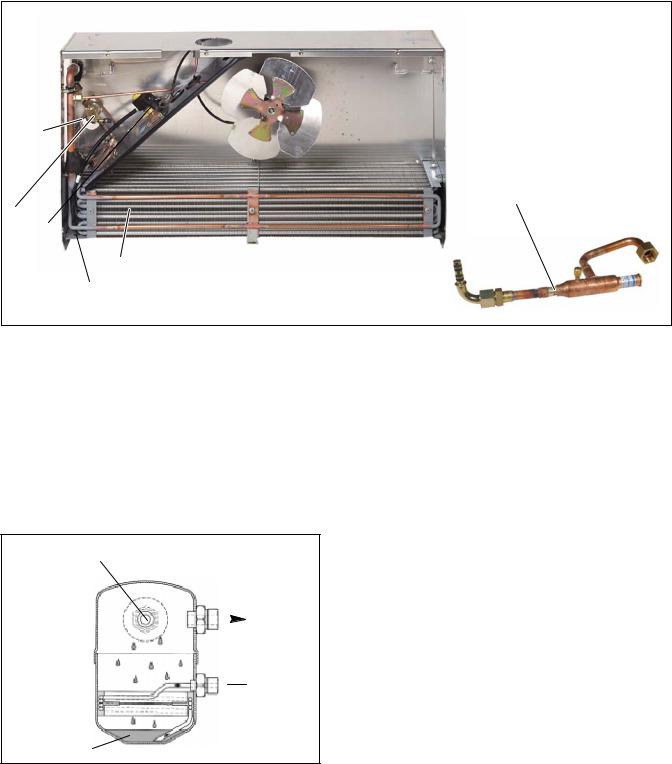
1.3 CONDENSING SECTION
The condensing section (see Figure 1-2) contains the condenser fan & coil, filter--drier, oil separator, hot gas solenoid valve, receiver, and a condenser pressure control valve. On road/standby units the condensing section also houses the standby compressor, control box and rectifier and houses the transformer assembly (see Figure 1-2 and Figure 1-5 ).
1.3.1 Condenser/Subcooler
The condenser is of the tube and fin type and acts as a heat exchanger in which the compressed refrigerant gas is condensed into a liquid and lowered in temperature. Air movement over the condenser is provided by a fan mounted in the condensing section.
A portion of the condenser is occupied by the subcooler. Refrigerant leaving the receiver is passed through the subcooler where additional heat is removed. Removal of this additional heat helps to ensure that only liquid refrigerant enters the thermal expansion valve.
1.3.2 Filter Drier
The drier is a cylindrical shell containing a drying agent and screen. It is installed in the liquid line and functions to keep the system clean and remove moisture from the refrigerant.
Table 1-1 Model Chart
|
|
|
R134a |
|
Road |
Standby |
|
Condenser Weight |
|
|
|||||
Model No. |
Description |
|
|
|
|
|
|
|
|
|
Evap. Wt. |
||||
LB |
|
Kg |
|
Compressor |
Compressor |
|
Road |
|
Road and |
|
|||||
|
|
|
|
|
|
|
Standby |
|
|
||||||
|
|
|
|
|
|
|
|
|
|
|
|
|
|
|
|
|
|
|
|
|
|
|
|
|
|
|
|
|
|
|
|
8002189 |
Road Only |
|
|
|
|
|
-- |
|
|
|
|
|
|
|
|
|
|
|
|
|
|
|
|
|
|
|
|
|
|
|
|
8002191 |
Road/Standby |
|
|
|
|
|
|
|
|
|
|
|
|
|
|
115/1/60Hz |
|
|
|
|
|
|
|
|
|
|
|
|
|
||
|
|
|
|
|
|
|
|
|
88 lb |
|
165 lb (75 |
|
66 lb (30 |
||
|
|
|
4 |
|
1.8 |
|
TM 16 |
|
|
|
|
|
|||
|
Road/Standby |
|
|
|
|
|
|
|
|||||||
8002193 |
|
|
TM 16 |
|
(40 kg) |
|
kg |
|
Kg) |
||||||
230/1/60Hz |
|
|
|
|
|
|
|
|
|||||||
|
|
|
|
|
|
|
|
|
|
|
|
|
|
||
|
|
|
|
|
|
|
|
|
|
|
|
|
|
|
|
8002195 |
Road/Standby |
|
|
|
|
|
|
|
|
|
|
|
|
|
|
230/3/60Hz |
|
|
|
|
|
|
|
|
|
|
|
|
|
||
|
|
|
|
|
|
|
|
|
|
|
|
|
|
||
|
|
|
|
|
|
|
|
|
|
|
|
|
|
|
|
|
|
|
|
Table 1-2. Additional Support Manuals |
|
|
|
|
|
||||||
|
|
|
|
|
|
|
|
|
|
||||||
Manual Number |
|
|
|
Equipment Covered |
|
|
|
Type of Manual |
|
||||||
|
|
|
|
|
|
|
|
|
|
|
|
|
|||
62--10835 |
|
|
|
|
Supra 30S |
|
|
|
|
|
Parts List |
|
|||
|
|
|
|
|
|
|
|
|
|
|
|
||||
62--10847 |
|
|
|
|
Supra 30S |
|
|
|
|
Easy To Run |
|
||||
|
|
|
|
|
|
|
|
|
|
|
|||||
62--10849 |
|
|
|
|
Supra 30S |
|
|
|
Operator’s Manual |
|
|||||
1-1 |
62-10848 |
1 1
CAB COMMAND 
|
|
Figure 1-1 Integra 30S |
|
|
2 |
3 |
4 |
5 |
6 |
 7
7
17
|
16 |
|
|
|
|
11 |
|
8 |
|
15 |
14 |
13 |
12 |
|
10 |
9 |
|
|
|
|
|
|||||
1. |
Nameplate |
|
|
|
10. |
Sight Glass |
|
|
2. |
Condenser Coil |
|
|
|
11. |
Receiver |
|
|
3. |
Transformer (TR) |
|
|
|
12. |
Discharge Manifold |
|
|
4. |
Oil Separator |
|
|
|
13. |
Hot Gas Solenoid Valve (HGS1) |
||
5. |
Standby Motor |
|
|
|
14. |
Condenser Pressure Control Switch (HP2) |
||
6. |
Standby Compressor (See Table 1-1) |
|
15. |
Frame |
|
|
||
7. |
Control Box |
|
|
|
16. |
High Pressure Switch (HP1) |
|
|
8. |
Filter Drier |
|
|
|
17. |
Condenser Pressure Control Valve (HGS2) |
||
9.Liquid Line Check Valve
Figure 1-2 Top View
62-10848 |
1-2 |
|
1 |
|
|
2 |
|
|
6 |
|
|
|
|
|
3 |
|
|
|
5 |
|
|
|
4 |
|
|
1. |
Low Pressure Switch (LP) |
5. |
Evaporator coil |
2. |
Expansion Valve (TXV) |
6. |
Compressor Pressure Regulating Valve |
3. |
Quench Valve (BPV) |
|
(CPR)115V only |
4.Defrost Termination Thermostat (DTT)
Figure 1-3 Rear View Evaporator
1.3.3 Oil Separator
The oil separator is installed in the discharge line from the road compressor. The hot gas coming from the compressor is forced through a filter which separates the gas from the oil. The oil collects at the bottom after passing through a second filter and then returns to the compressor via a capillary tube.
OIL AND GAS- |
REFRIGERANT |
||
FROM COMP. |
GAS TO |
||
|
|||
|
COND. |
||
|
|
|
|
 OIL TO
COMP.
SUCTION
LINE
OIL
Figure 1-4 Oil Separator 1.3.4 Hot Gas Solenoid Valve (HGS1)
HGS1 is normally closed and prevents discharge gas from entering the evaporator. The valve opens to allow hot gas refrigerant to be delivered from the compressor to the evaporator during heat or defrost modes.
1.3.5 Condenser Pressure Control Valve (HGS2)
The condenser pressure control valve (or condenser closing valve) is a normally open valve that is powered when the condenser pressure control switch (HP2) is closed. With the solenoid coil de-energized, the valve is in the cool mode and the compressor discharge gas is delivered to the condenser. In the cool mode, heat is removed from the air inside the truck body and rejected to the surrounding air. With the solenoid coil energized, the valve is in the heat mode and the compressor discharge gas is diverted to the evaporator and rejected to the air inside the truck body.
1.3.6 Compressor
The compressor withdraws refrigerant gas from the evaporator and delivers it to the condenser at an increased pressure. The pressure is such that refrigerant heat can be absorbed by the surrounding air at ordinary temperatures.
1.3.7 Standby Motor
The standby |
motor |
operates on nominal |
|
115v--1ph--60hz |
or |
208/230v--1ph--60hz |
or |
230v--3ph--60hz power. An overload and short cycle protection is provided along with automatic reset. Units are also equipped with a remote mounted power receptacle.
1.3.8 Receiver
Liquid refrigerant from the condenser is deliver to the receiver. The receiver serves as a liquid reservoir when there are surges due to load changes in the system; as a storage space when pumping down the system and as a liquid seal against the entrance of refrigerant gas into the liquid line.
1-3 |
62-10848 |
1.3.9 High Pressure Switch (HP1)
HP1 is a normally closed switch which monitors the system for high pressure and shuts down the unit when pressure rises above predetermined setting. For HP1 settings see Section 1.6.2.
1.3.10 Condenser Pressure Control Switch (HP2)
HP2 is a normally open switch which closes to signal the microprocessor to activate the condenser fan. HP2 also cycles the condenser pressure control valve (HGS2) and the quench valve (BPV) in addition to the condenser fan in order to maintain head pressure for heating capacity. For HP2 settings see Section 1.6.2.
1.4 EVAPORATOR SECTION
The evaporator assembly consists of an evaporator fan, evaporator coil, thermostatic expansion valve, defrost termination thermostat, a compressor pressure regulating valve (115V only) and a quench valve.
1.4.1 Thermostatic Expansion Valve
The thermostatic expansion valve is an automatic device which controls the flow of liquid to the evaporator according to changes in superheat to the refrigerant leaving the evaporator. The thermal expansion valve maintains a relatively constant degree of superheat in the gas leaving the evaporator regardless of suction pressure. Thus, the valve has a dual function; automatic expansion control and preventing liquid from returning to the compressor. For TXV superheat settings see Section 1.6.2. To adjust the TXV, refer to Section 4.15.2.
1.4.2Compressor Pressure Regulating Valve (CPR) (115V Only) (See Figure 1-3)
The CPR valve is installed on the suction line of the standby compressor to regulate the suction pressure entering the compressor. The CPR valve is set to limit the maximum suction pressure. For CPR settings refer to section 1.6.2.
The suction pressure is controlled to avoid overloading the electric motor during high box temperature operation. To adjust the CPR valve, refer to section 4.17
1.4.3 Defrost Termination Thermostat (DTT)
Normally closed thermal switch on Standby units only. As evaporator cools to setpoint, the switch closes and signals microprocessor that defrost may be initiated. Switch terminates defrost by opening at predetermined setpoint. For DTT settings refer to section 1.6.2.
1.4.4 Quench Valve (BPV)
The quench valve is a normally closed solenoid valve controlled by the quench thermostat (BPT) mounted on the road compressor discharge line. The valve allows metered liquid refrigerant to enter the suction line in the evaporator in order to provide compressor cooling. For BPT settings refer to section 1.6.2.
1.4.5 Evaporator
The evaporator is of the tube and fin type. The operation of the compressor maintains a reduced pressure within the coil. At this reduced pressure, the liquid refrigerant evaporates at a temperature sufficiently low enough to absorb heat from the air. Air movement over the evaporator is provided by an electric fan.
1.4.6 Low Pressure Switch (LP)
The low pressure switch is a normally closed switch which signals the microprocessor to shut down the unit when the system is outside the low pressure limit. For LP settings refer to section 1.6.2.
62-10848 |
1-4 |

5 |
6 |
7 |
8 |
9 |
|
|
|
4
3
10
2
11
1
14
13
115/1/60
12 |
12 |
13 |
115/1/60 |
||
|
230/1/60 |
230/1/60 |
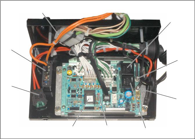
1. |
Standby clutch fuse (F2) -- 30 Amp |
8. |
Diode |
2. |
Standby Fuse (F3) -- 5 Amp |
9. |
Rectifier Bridge Assembly (BR) |
3. |
Transformer Fuse (F4) -- 5 Amp |
10. |
Filter Capacitor (C1) |
4. |
Clutch Time Delay Relay (CT) -- Single Phase |
11. |
Start Relay (STBR) |
|
Only |
12. |
Run Capacitor (CR) |
5. |
Clutch Relay (CR) |
13. |
Start Capacitor (CS) |
6. |
Motor Contactor (MC) |
14. |
Heat sink (rectifier bridge) |
7.Overload Relay (OL) (230V Only)
Figure 1-5 Typical Standby Control Box
1-5 |
62-10848 |
1
2
9
3
8
4
|
|
7 |
6 |
5 |
1. |
Connector |
6. |
C_ or F_ Temperature Selector |
|
2. |
Road Relay (RR) |
7. |
Microprocessor (PC) |
|
3. |
12 |
Volt dc Road Connection |
8. |
Road Fuse (F1) 30A |
4. |
12 |
Volt dc Standby Connection |
9. |
Overload Relay (OL) 25A (115V Only) |
5.Standby Relay (SR)
Figure 1-6 Standby Microprocessor Module
62-10848 |
1-6 |
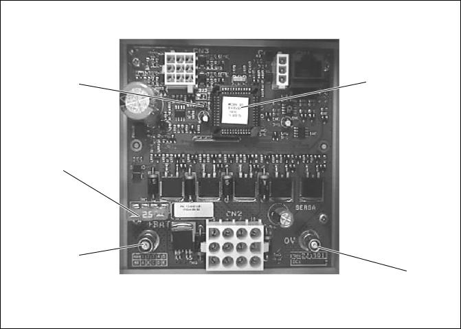
1 |
5 |
|
2
3
4
1.C_ or F_ Temperature Selector
2.Road fuse (25A)
3.+ Positive Battery Connection
4.-- Negative Battery Connection
5.--Microprocessor (PC)
Figure 1-7 Road Microprocessor Module
1-7 |
62-10848 |
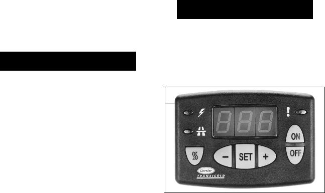
1.5SYSTEM OPERATING CONTROLS AND COMPONENTS
The unit is furnished with a microprocessor control system. Once the setpoint is entered at the Cab Command, the unit will operate automatically to maintain the desired temperature within very close limits.
 WARNING
Beware of unannounced starting of the, standby motor, evaporator fan or condenser fan. The unit may cycle the standby motor or fans unexpectedly as control requirements dictate.
The control system consists of the Cab Command located in the driver’s section (See Figure 1-8) and the microprocessor module (See Figure 1-6) located in the control box.
The Carrier Transicold Control System incorporates the following features:
a.Control return air temperature to tight limits by providing refrigeration control, heat and defrost to ensure conditioned air delivery to the load.
b.Permanently displays the return air temperature and on request the setpoint temperature.
c.Digital display and selection of data.
 CAUTION
Under no circumstances should anyone attempt to repair the microprocessor module or Cab Command! Should a problem develop with these components, contact your nearest Carrier Transicold dealer for replacement.
Figure 1-8 Cab Command
62-10848 |
1-8 |
1.6 |
UNIT SPECIFICATIONS |
|
||
1.6.1 |
Compressor Data |
|
|
|
|
|
|
|
|
|
Model |
|
|
TM 16 |
|
|
|
|
|
Displacement |
|
( |
9.9 in33 |
|
|
|
|
|
162 cm ) |
No. Cylinders |
|
|
6 |
|
|
|
|
|
|
|
|
|
|
15.5 lbs |
|
Weight |
|
|
(7 kg) |
|
|
|
|
|
|
Oil Charge |
|
5.07in3 (180 cm3) |
|
Approved Oil |
|
Mobil Arctic EAL68 |
||
|
|
|
|
|
1.6.2 Refrigeration System Data a. Defrost Timer
Automatic triggering or at preset intervals : 0 (Disabled), auto, 1h, 2h, 3h, 4h, 5h, 6h
b.Defrost Termination Thermostat (DTT) (Standby Only)
Opens at: 48_ ¦ 5_F (9_ ¦ 3_C)
Closes at: 37_ ¦ 5_F (3_ ¦ 3_C)
c.High Pressure Switch (HP1)
Cutout at : 355 psig ± 10 PSI (24.5 bars) Cut-in at : 290 psig ± 10 PSI (20 bars)
d.Condenser Pressure Control Switch (HP2)
Cutout at : 130 psig ± 10 PSI (9 bars) Cut-in at : 175 psig ± 10 PSI (12 bars)
e.Refrigerant charge
Refer to Table 1-1.
f.Compressor Pressure Regulating Valve (CPR) 115V only
19±1 psig (1.3 Bar)
g. Thermostatic Expansion Valve (TXV)
Superheat setting = 4_C (7 ¦ 1_F) at box temperature of -20_C (0_F).
h. Low Pressure switch (LP)
Cutout at : --13.23 inHG ± 6 inHG (-- 0.45 ± 0.2 bar)
Cut-in at : +6.5 psig ± 3 psig (+0.44 ± 0.2 bar)
i. Quench Thermostat (BPT)
Opens at: 248_F (120_C) Closes at: 220_F (104_C)
1-9 |
62-10848 |
 Loading...