


50GS042300
50GS
50Hz Electric Cooling Units
%isitx__ _.carrier.com
A Guide to Operating and Maintaining Your
Single-Packaged Electric Cooling Units
NFATUNG & COOLING
NOTE: Read the entire instruction manual bellk_re starting the
installation.
SAFETY CONSIDERATIONS
Note to h_stal[er:This manual should be left with the equipment
user.
Do not store or use gasoline or other flamnmble wq_ors and
liquids in the vicinity of these or any other appliances. Failure
to follow this warning could result in fire, serious injury, or
death.
Do not use either of these malts if any part has been under
water. Immediately call a qualified service technician to
inspect the unit and to replace any part of the control system
which has been under water. Failure to _k_llow this warning
could result in electrical shock, fire, serious injury, or death.
Be%re per%rming recommended maintenance, be sure the
main power switch to unit is turned off and lock-out tag
installed. Electric shock could cause serious it{jury or death.
STARTING OR SHUTTING UNIT OFF
1. To start this unit:
a. Turn on the electrical power supply to unit.
b. Select temperature and set SYSTEM switch or MODE
control to desired mode.
2. To shut this unit off:
NOTE: If the unit is being shut down because of a malNnction,
call your dealer as soon as possible.
a. Set system SWITCH or MODE contlol to OFF.
b. Turn off the electrical power supply to unit and install
lock-out tag.
OPERATING YOUR ELECTRIC AmR CONDITIONER
The operation of'your system is conholled by the indoor thermo-
stat. You simply adjust the thermostat and it maintains the indoor
temperature at the level you select. Most themaostats have 3
controls: a temperature control selector, a FAN control, and a
SYSTEM or MODE control. RefEr to your thermostat owner's
manual for more infbrmation.
To better protect your investment and to eliminate unnecessa_
sela'ice calls, familiarize yourself with the %llowing g_cts:
Step l--Cooling Mode
With the SYSTEM or MODE control set to COOL, your unit will
run in cooling mode until the indoor temperature is lowered to the
level you have selected. On extlemely hot days, your system will
run for longer periods at a time and have shorter "o_t" periods than
on moderate days.
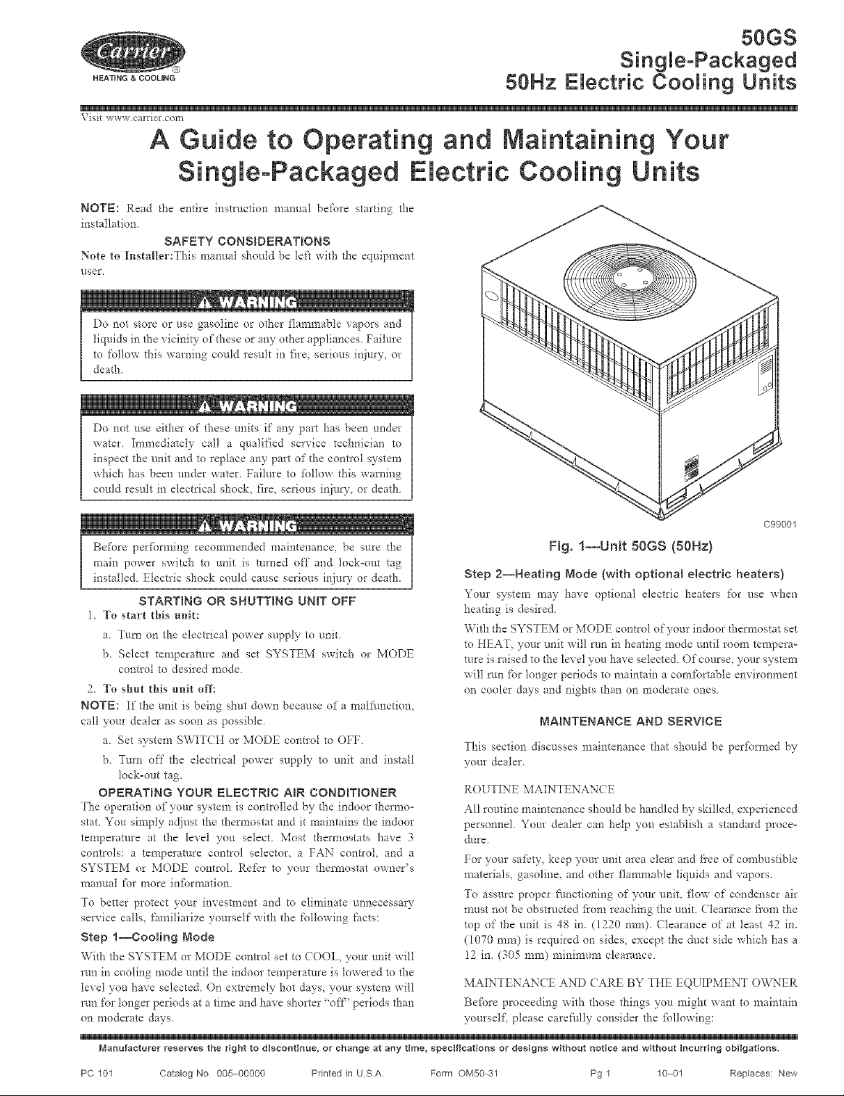
Fig. 1--Unit 50GS (80Hz)
C99001
Step 2--Heating Mode (with optional electric heaters)
Your system may have optional electric heaters for use when
heating is desired.
With the SYSTEM or MODE control of your indoor thermostat set
to HEAT, your unit will rnn in heating mode until room tempera°
rare is raised to the level you have selected. Of course, your systenr
will run fbr longer periods to maintain a comfortable environment
on cooler days and nights than on moderate ones.
MAINTENANCE AND SERVICE
This section discusses maintenance that should be per%treed by
your dealer.
ROUTINE MAINTENAN< E
All routine maintenance should be handled by skilled, experienced
personnel Your dealer can help you establish a standard proce-
dure
For your safety, keep your unit area clear and thee of combustible
materials, gasolin< and other flammable liquids and vapors.
To assure proper ffinctioning of your unit, flow of condenser air
must not be obstructed fi'om reaching the unit. Clearance fi'om the
top of the unit is 48 in. (1220 ram). Clearance of at least 42 in.
(I070 ram) is required on sides, except the duct side which has a
12 in. (305 ram) minimum clearance.
MAINTENANCE AND <7ARE BY THE EQUIPMENT OVv_ER
Befbre proceeding with those things you might want to maintain
yourself, please careffilly consider the _bllo_;ing:
Manufacturer reserves the right to discontinue, or change at any time, specifications or designs without notice and without incurring obligations.
PC 101 Catalog No 005-00000 Printed in U.S.A Form OM50-31 Pg 1 10-01 Replaces: New
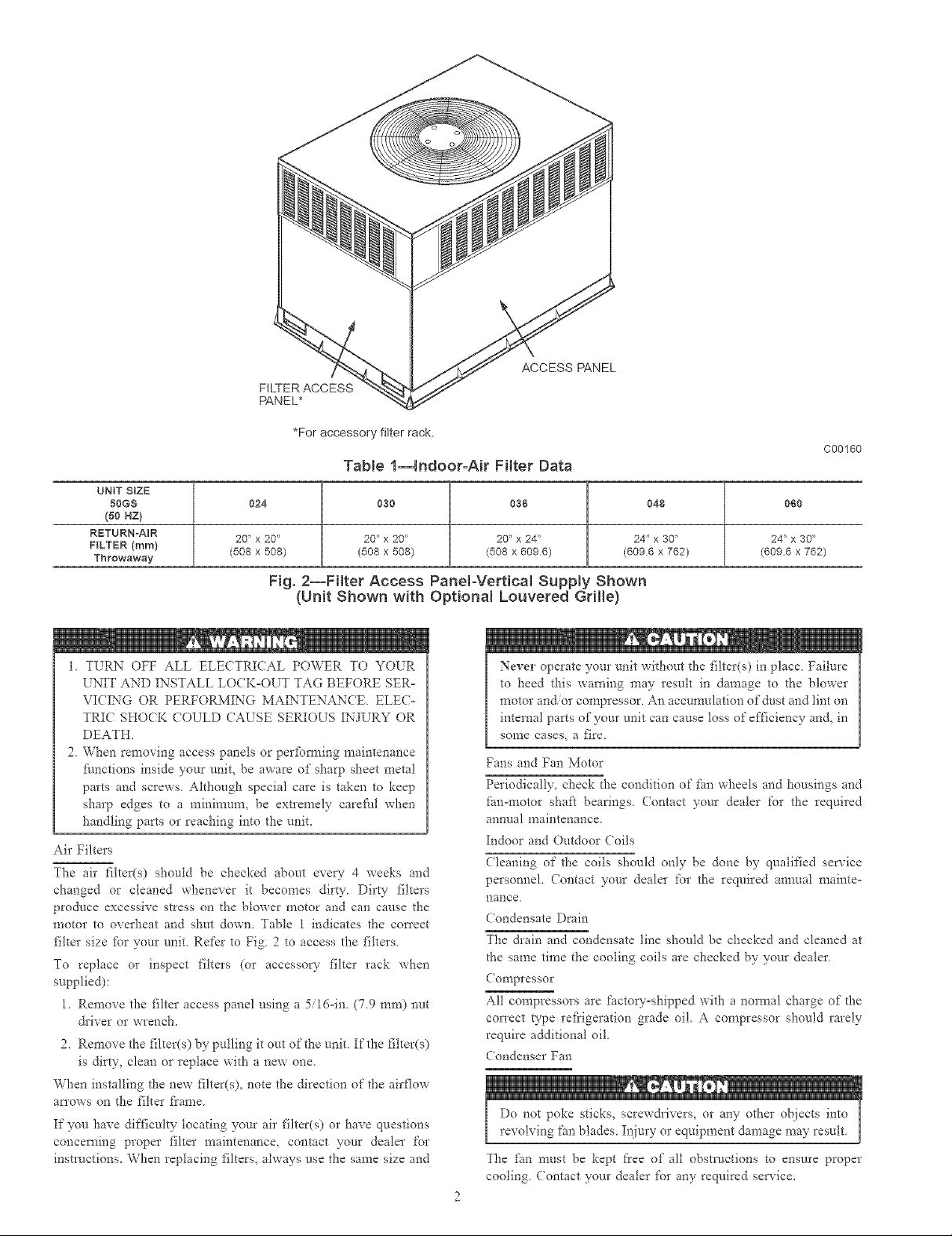
ACCESS PANEL
FILTER ACCESS
PANEL*
*For accessory fitterrack.
Tab{e I--Indoor-Air Filter Data
UNIT SIZE
50GS 060
(50 NZ)
RETURN=A_R 24" x 30"
FILTER (ram / (609.6 x 762)
Throwaway
024 030 036 048
20" x 20" 20" x20" 20" x 24" 24" x 30"
(508 x 508) (508 x 508) (508 x 6096) (6096 x 762)
Fig. 2--Filter Access PaneloVertical SuppJy Shown
(Unit Shown with OptionN Louvered Grille)
C00160
1. TURN OFF ALL ELECTRICAL POWER TO YOER
UNIT AND INSTALL LO(K-OUT TAG BEFORE SER-
VICING OR PERFORMING MArNTENANCE ELEC-
TRIC SHOCK COULD (AUSE SERIOUS INJURY OR
DEATH.
2. When removing access panels or perfbmaing maintenance
Nnctions inside your unit, be aware of sharp sheet metal
parts and screws. Although special care is taken to keep
sharp edges to a minimum, be extremely careNl when
handling parts or reaching into the unit.
Air Filters
The air filter(s) should be checked about eve N- 4 weeks and
changed or cleaned whenever it becomes dirty. Dirty filters
produce excessive stress on the blower motor and can cause the
motor to overheat and shut down. Table 1 indicates the correct
filter size fbr your unit. Refer to Fig. 2 to access the filters.
To replace or inspect filters (or accessory filter rack when
supplied):
1. Remove the filter access panel using a 5i16oin. (7.9 ram) nut
&iver or wrench.
2. Remove the filter(s) by pulling it out of the unit. If the filter(s)
is dirt?-, clean or replace with a new one.
When installing the new filter(s), note the direction of the airflow
an'ows on the filter frame.
If you have difficulty locating your air filter(s) or have questions
concerning proper filter maintenance, contact your dealer for
instructions. When replacing filters, always use the same size and
Never operate your malt without d_e filter(s) in place Failure
to heed this warning may result in damage to the blower
motor and/or compressor. An accun-mlation of dust and tint on
internal parts of your unit can cause loss of efficiency and, in
sonle cases, a fire.
Fans and Fan Motor
Periodically, check the condition of fhn wheels and housings and
fanomotor shafl bearings. (ontact your dealer for the required
annual maintenance.
Indoor and Outdoor Coils
(?leaning of the coils should only be done by qualified service
personnel. (ontact your dealer for the required annual mainteo
nance.
Condensate Drain
The &ain and condensate line should be checked and cleaned at
the same time the cooling coils are checked by your dealer.
Compressor
All compressors are factov-shipped with a normal charge of d-_e
correct type ref?igeration grade oil. A compressor should rarely
require additional oil.
Condenser Fan
, 0 !
Do not poke sticks, screw&ivers, or any other objects into
revolving ['an blades. Injury or equipment damage may result.
The finn n-rest be kept flee of all obstructions to ensure proper
cooling Contact your dealer for any required service.
2
 Loading...