


50GS, 50GX Single Packaged Electric Cooling Units
Visit www.carrier.com
Installation, Start-Up, and Operating Instructions 50GS Sizes 018-060, 50GX Sizes 024-060
NOTE: Read the entire instruction manual before starting the installation.
This symbol → indicates a change since the last issue.
TABLE OF CONTENTS |
|
SAFETY CONSIDERATIONS ..................................................... |
1 |
Introduction .................................................................................... |
2 |
RECEIVING AND INSTALLATION .......................................... |
2 |
Check Equipment...................................................................... |
2 |
IDENTIFY UNIT ................................................................ |
2 |
INSPECT SHIPMENT........................................................ |
2 |
Provide Unit Support................................................................ |
2 |
ROOF CURB....................................................................... |
2 |
SLAB MOUNT ................................................................... |
2 |
GROUND MOUNT ............................................................ |
2 |
Provide Clearances.................................................................... |
2 |
Field Fabricate Ductwork ......................................................... |
2 |
Rig and Place Unit.................................................................... |
2 |
INSPECTION ...................................................................... |
3 |
INSTALLATION ................................................................ |
3 |
Connect Condensate Drain ....................................................... |
7 |
Install Duct Connections .......................................................... |
7 |
CONFIGURING UNITS FOR DOWNFLOW (VERTI- |
|
CAL) DISCHARGE............................................................ |
8 |
Install Electrical Connection .................................................... |
9 |
HIGH-VOLTAGE CONNECTIONS................................ |
10 |
SPECIAL PROCEDURES FOR 208-V OPERATION ... |
10 |
CONTROL VOLTAGE CONNECTIONS....................... |
10 |
STANDARD CONNECTION .......................................... |
10 |
TRANSFORMER PROTECTION.................................... |
13 |
PRE-START-UP .......................................................................... |
13 |
START-UP ................................................................................... |
14 |
CHECK FOR REFRIGERANT LEAKS.......................... |
14 |
START UP COOLING SECTION AND MAKE ADJUST- |
|
MENTS.............................................................................. |
14 |
CHECKING COOLING CONTROL OPERATION ....... |
14 |
CHECKING AND ADJUSTING REFRIGERANT |
|
CHARGE ........................................................................... |
14 |
INDOOR AIRFLOW AND AIRFLOW ADJUST- |
|
MENTS.............................................................................. |
18 |
For 208/230V..................................................................... |
18 |
FOR 460-V GE MOTORS................................................ |
18 |
COOLING SEQUENCE OF OPERATION..................... |
18 |
MAINTENANCE......................................................................... |
18 |
AIR FILTER...................................................................... |
22 |
EVAPORATOR BLOWER AND MOTOR..................... |
22 |
CONDENSER COIL, EVAPORATOR COIL, AND CON- |
|
DENSATE DRAIN PAN.................................................. |
24 |
CONDENSER FAN .......................................................... |
24 |
ELECTRICAL CONTROLS AND WIRING .................. |
24 |
REFRIGERANT CIRCUIT............................................... |
24 |
EVAPORATOR AIRFLOW ............................................. |
25 |
METERING DEVICE — ACUTROL DEVICE |
.............25 |
LIQUID LINE STRAINER .............................................. |
25 |
Troubleshooting............................................................................ |
25 |
Start-Up Checklist........................................................................ |
25 |
NOTE TO INSTALLER — Before the installation, READ THESE INSTRUCTIONS CAREFULLY AND COMPLETELY. Also, make sure the User’s Manual and Replacement Guide are left with the unit after installation.
SAFETY CONSIDERATIONS
Installation and servicing of air-conditioning equipment can be hazardous due to system pressure and electrical components. Only trained and qualified personnel should install, repair, or service air-conditioning equipment.
Untrained personnel can perform basic maintenance functions of cleaning coils and filters. All other operations should be performed by trained service personnel. When working on air-conditioning equipment, observe precautions in the literature, tags, and labels attached to the unit, and other safety precautions that may apply.
Follow all safety codes. Wear safety glasses and work gloves. Use quenching cloth for unbrazing operations. Have fire extinguisher available for all brazing operations. Consult a qualified installer or service agency for information or assistance. The qualified installer or agency must use only factory-authorized kits or accessories when modifying this product.
C99001
Fig. 1—Unit 50GS and 50GX
Manufacturer reserves the right to discontinue, or change at any time, specifications or designs without notice and without incurring obligations.
Book |
1 |
6 |
PC 101 |
Catalog No. 535–00130 |
Printed in U.S.A. |
Form 50GS,GX-4SI |
Pg 1 |
9–03 |
Replaces: 50GS,GX-3SI |
Tab |
6 8 |
|
|
|
|
|
|
|
|
Before performing service or maintenance operations on system, turn off power to unit. Turn off accessory heater power switch, if applicable. Electrical shock can cause personal injury.
Recognize safety information. This is the safety-alert symbol . When you see this symbol in instructions or manuals, be alert to the potential for personal injury.
Understand the signal words DANGER, WARNING, CAUTION, and NOTE. These words are used with the safety-alert symbol. DANGER identifies the most serious hazards which will result in severe personal injury or death. WARNING signifies a hazard which could result in personal injury or death. CAUTION is used to identify unsafe practices which would result in minor personal injury or product and property damage. NOTE is used to highlight suggestions which will result in enhanced installation, reliability, or operation.
These instructions cover minimum requirements and conform to existing national standards and safety codes. In some instances, these instructions exceed certain local codes and ordinances, especially those that may not have kept up with changing residential construction practices. We require these instructions as a minimum for a safe installation.
INTRODUCTION
The 50GS and 50GX units (see Fig. 1) are fully self-contained, and designed for outdoor installation. See Figs. 2 and 3 for unit dimensions. All unit sizes have discharge openings for both horizontal and downflow configurations, and are factory shipped with all downflow duct openings covered . Units may be installed either on a rooftop, ground-level cement slab, or directly on the ground if local codes permit. (See Fig. 4A for roof curb dimensions.)
RECEIVING AND INSTALLATION Step 1—Check Equipment
IDENTIFY UNIT
The unit model number and serial number are stamped on the unit identification plate. Check this information against shipping papers.
INSPECT SHIPMENT
Inspect for shipping damage while unit is still on shipping pallet. If unit appears to be damaged or is torn loose from its anchorage, have it examined by transportation inspectors before removal. Forward claim papers directly to transportation company. Manufacturer is not responsible for any damage incurred in transit. Check all items against shipping list. Immediately notify the nearest Carrier Air Conditioning office if any item is missing. To prevent loss or damage, leave all parts in original packages until installation.
Step 2—Provide Unit Support
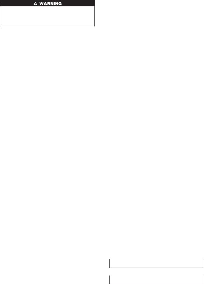
ROOF CURB
Install accessory roof curb in accordance with instructions shipped with curb (See Fig. 4A). Install insulation, cant strips, roofing, and flashing. Ductwork must be attached to curb.
IMPORTANT: The gasketing of the unit to the roof curb is critical for a watertight seal. Install gasketing material supplied with the roof curb. Improperly applied gasketing also can result in air leaks and poor unit performance.
Curb should be level to within 1/4 in. (See Fig. 5A). This is necessary for unit drain to function properly. Refer to accessory roof curb installation instructions for additional information as required.
SLAB MOUNT
Place the unit on a solid, level concrete pad that is a minimum of 4 in. thick with 2 in. above grade (See Fig. 5B). The slab should extend approximately 2 in. beyond the casing on all 4 sides of the unit. Do not secure the unit to the slab except when required by local codes.
GROUND MOUNT
The unit may be installed either on a slab or placed directly on the ground if local codes permit. Place the unit on level ground prepared with gravel for condensate discharge.
Step 3—Provide Clearances
The required minimum service clearances are shown in Fig. 2 & 3. Adequate ventilation and outdoor air must be provided. The outdoor fan draws air through the outdoor coil and discharges it through the top fan grille. Be sure that the fan discharge does not recirculate to the outdoor coil. Do not locate the unit in either a corner or under an overhead obstruction. The minimum clearance under a partial overhang (such as a normal house overhang) is 36 in. above the unit top. The maximum horizontal extension of a partial overhang must not exceed 48 in. For extended overhangs, provide a minimum clearance of 48 in.
IMPORTANT: Do not restrict outdoor airflow. An air restriction at either the outdoor-air inlet or the fan discharge may be detrimental to compressor life.
Do not place the unit where water, ice, or snow from an overhang or roof will damage or flood the unit. Do not install the unit on carpeting or other combustible materials. Slab-mounted units should be at least 4 in. above the highest expected water and runoff levels. Do not use unit if it has been under water.
Step 4—Field Fabricate Ductwork
Secure all ducts to roof curb and building structure on vertical discharge units. Do not connect ductwork to unit. For horizontal applications, unit is provided with flanges on the horizontal openings. All ductwork should be secured to the flanges. Insulate and weatherproof all external ductwork, joints, and roof openings with counter flashing and mastic in accordance with applicable codes.
Ducts passing through an unconditioned space must be insulated and covered with a vapor barrier. If a plenum return is used on a vertical unit, the return should be ducted through the roof deck to comply with applicable fire codes. A minimum clearance is not required around ductwork. Cabinet return-air static shall not exceed -.25 in. wg.
Step 5—Rig and Place Unit
Rigging and handling of this equipment can be hazardous for many reasons due to the installation location (roofs, elevated structures, etc.)
Only trained, qualified crane operators and ground support staff should handle and install this equipment.
When working with this equipment, observe precautions in the literature, on tags, stickers, and labels attached to the equipment, and any other safety precautions that might apply.
Follow all applicable safety codes. Wear safety shoes and work gloves.
Never stand beneath rigged units or lift over people.
Never exceed 200 lbs. per bracket lifting force.
2

REQUIRED CLEARANCE TO COMBUSTIBLE MATL.
|
INCHES [mm] |
|
TOP OF UNIT................................................................................... |
14.00 |
[355.6] |
DUCT SIDE OF UNIT......................................................................... |
2.00 |
[50.8] |
SIDE OPPOSITE DUCTS ................................................................ |
14.00 |
[355.6] |
BOTTOM OF UNIT ............................................................................. |
0.50 |
[12.7] |
ELECTRIC HEAT PANEL ................................................................. |
36.00 |
[914.4] |
NEC. REQUIRED CLEARANCES. |
INCHES [mm] |
|
|
||
BETWEEN UNITS, POWER ENTRY SIDE .................................... |
42.00 [1066.8] |
|
UNIT AND UNGROUNDED SURFACES, POWER ENTRY SIDE .36.00 [914.0] |
||
UNIT AND BLOCK OR CONCRETE WALLS AND OTHER |
|
|
GROUNDED SURFACES, POWER ENTRY SIDE......................... |
42.00 [1066.8] |
|
REQUIRED CLEARANCE FOR OPERATION AND SERVICING
|
INCHES [mm] |
|
EVAP. COIL ACCESS SIDE............................................................ |
36.00 |
[914.0] |
POWER ENTRY SIDE.................................................................... |
42.00 |
[1066.8] |
(EXCEPT FOR NEC REQUIREMENTS) |
|
|
UNIT TOP ....................................................................................... |
48.00 |
[1219.2] |
SIDE OPPOSITE DUCTS .............................................................. |
36.00 |
[914.0] |
DUCT PANEL ................................................................................. |
12.00 |
[304.8] * |
*MINIMUM DISTANCES: IF UNIT IS PLACED LESS THAN 304.8 [12.00] FROM WALL SYSTEM, THEN SYSTEM PERFORMANCE MAYBE COMPROMISE.
C99007
|
|
UNIT WEIGHT |
UNIT HEIGHT |
CENTER OF GRAVITY |
|||
UNIT |
ELECTRICAL CHARACTERISTICS |
IN. (MM) |
|
IN. (MM) |
|
||
|
|
|
|
||||
|
|
lb. |
kg |
”A” |
X |
Y |
Z |
50GS018 |
208/230-1-60 |
254 |
115.2 |
35.02 (889.5) |
20.0 (508.0) |
13.0 (330.2) |
15.0 (381.0) |
50GS024 |
208/230-1-60 |
260 |
117.9 |
35.02 (889.5) |
19.0 (482.6) |
13.0 (330.2) |
15.0 (381.0) |
50GS030 |
208/230-1-60, 208/230-3-60 |
258 |
117.0 |
35.02 (889.5) |
19.0 (482.6) |
14.0 (355.6) |
15.0 (381.0) |
50GS036 |
208/230-1-60, 208/230-3-60, 460-3-60 |
268 |
121.6 |
37.02 (940.3) |
20.0 (508.0) |
14.0 (355.6) |
13.0 (330.2) |
50GS042 |
208/230-1-60, 208/230-3-60, 460-3-60 |
294 |
133.3 |
35.02 (889.5) |
19.0 (482.6) |
14.0 (355.6) |
13.0 (330.2) |
50GX024 |
208/230-1-60 |
270 |
122.5 |
37.02 (940.3) |
18.5 (469.9) |
14.5 (368.3) |
16.0 (406.4) |
50GX030 |
208/230-1-60, 208/230-3-60 |
291 |
132.0 |
39.02 (991.1) |
19.5 (495.3) |
15.5 (393.7) |
17.6 (447.0) |
50GX036 |
208/230-1-60, 208/230-3-60, 460-3-60 |
299 |
135.6 |
35.02 (889.5) |
19.5 (495.3) |
15.25 (387.4) |
16.5 (419.1) |
Fig. 2— 50GS018-042 and 50GX024-036 Unit Dimensions
Accessory lifting kit is only to be used with Small Packaged units which have a composite base pan with molded rigging holds.
of wear, structural deformation, or cracks. Particular attention should be paid to excessive wear at hoist hooking points and load support areas. Brackets or straps showing any kind of wear in these areas must not be used and should be discarded.
INSTALLATION
INSPECTION
Prior to initial use, and at monthly intervals, all rigging brackets and straps should be visually inspected for any damage, evidence
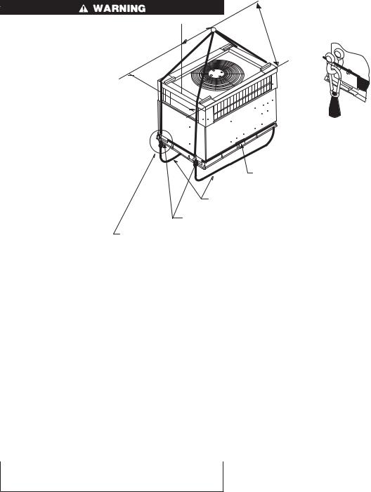
1.Position the lifting bracket assembly around the base of the unit. Leave the top shipping skid on the unit to act as a spreader bar. Be sure the strap does not twist.
3

REQUIRED CLEARANCE TO COMBUSTIBLE MATL.
|
INCHES |
[mm] |
TOP OF UNIT................................................................................... |
14.00 |
[355.6] |
DUCT SIDE OF UNIT......................................................................... |
2.00 |
[50.8] |
SIDE OPPOSITE DUCTS ................................................................ |
14.00 |
[355.6] |
BOTTOM OF UNIT ............................................................................. |
0.50 |
[12.7] |
ELECTRIC HEAT PANEL ................................................................. |
36.00 |
[914.4] |
NEC. REQUIRED CLEARANCES. |
INCHES [mm] |
|
|
||
BETWEEN UNITS, POWER ENTRY SIDE .................................... |
42.00 [1066.8] |
|
UNIT AND UNGROUNDED SURFACES, POWER ENTRY SIDE .36.00 [914.0] |
||
UNIT AND BLOCK OR CONCRETE WALLS AND OTHER |
|
|
GROUNDED SURFACES, POWER ENTRY SIDE......................... |
42.00 [1066.8] |
|
REQUIRED CLEARANCE FOR OPERATION AND SERVICING
|
INCHES [mm] |
|
EVAP. COIL ACCESS SIDE............................................................ |
36.00 |
[914.0] |
POWER ENTRY SIDE.................................................................... |
36.00 |
[914.0] |
(EXCEPT FOR NEC REQUIREMENTS) |
|
|
UNIT TOP ....................................................................................... |
48.00 |
[1219.2] |
SIDE OPPOSITE DUCTS .............................................................. |
36.00 |
[914.0] |
DUCT PANEL ................................................................................. |
12.00 |
[304.8] * |
*MINIMUM DISTANCES: IF UNIT IS PLACED LESS THAN 304.8 [12.00] FROM WALL SYSTEM, THEN SYSTEM PERFORMANCE MAYBE COMPROMISE.
C99006
|
|
UNIT WEIGHT |
UNIT HEIGHT |
CENTER OF GRAVITY |
|||
UNIT |
ELECTRICAL CHARACTERISTICS |
IN. (MM) |
|
IN. (MM) |
|
||
|
|
|
|
||||
|
|
lb. |
kg |
”A” |
X |
Y |
Z |
|
|
|
|
|
|
|
|
50GS048 |
208/230-1-60, 208/230-3-60, 460-3-60 |
324 |
145 |
38.98 (990.2) |
20.0 (508.0) |
17.0 (432.0) |
17.0 (432.0) |
50GS060 |
208/230-1-60, 208/230-3-60, 460-3-60 |
389 |
176 |
38.98 (990.2) |
19.0 (482.6) |
16.0 (406.0) |
17.0 (432.0) |
50GX042 |
208/230-1-60, 208/230-3-60, 460-3-60 |
321 |
146 |
38.98 (990.2) |
20.5 (520.7) |
16.75 (425.5) |
16.6 (421.6) |
50GX048 |
208/230-1-60, 208/230-3-60, 460-3-60 |
326 |
148 |
38.98 (990.2) |
19.5 (495.3) |
17.6 (447.6) |
18.0 (457.2) |
50GX060 |
208/230-1-60, 208/230-3-60, 460-3-60 |
399 |
181 |
42.98 (1091.1) |
20.5 (520.7) |
16.2 (412.8) |
17.6 (447.0) |
|
|
|
|
|
|
|
|
Fig. 3— 50GS048–060 and 50GX042–060 Unit Dimensions
2.Place each of the four (4) metal lifting brackets into the rigging holds in the composite pan.
3.Tighten the ratchet strap unit tight. Lifting brackets should be secure in the rigging holds.
4.Attach the clevis or hook of sufficient strength to hole in the lifting bracket (See Fig. 6).
5.Attach safety straps directly to the field supplied rigging straps or clevis clip. Do not attach the safety straps to the lifting brackets.
6.Use the top of the unit as a spreader bar to prevent the rigging straps from damaging the unit. If the wood top is not available, use a spreader bar of sufficient length to not damage the unit.
4
HVACunit
base 
Screw |
Gasketing |
(NO TE A) |
inner flange* |
*Gasketing |
|
outer flange |
|
|
Wood nailer* |
Flashing field |
|
supplied |
Roofcurb* |
|
Insulation(field |
Roofing material |
supplied) |
|
|
field supplied |
|
|
Duct wo rk |
Cant strip |
field supplied |
|
|
field supplied |
|
|
Roof |
*Provided with roofcurb |
|
Roof Curb for Small Cabinet
HVAC unit |
|
base |
|
|
Gask eting |
Screw |
inner flange* |
|
|
(NOTE A) |
|
*Gasketing |
|
outer flange |
|
|
Wood nailer* |
Flashing field |
|
supplied |
Roofcurb* |
|
Insulation(field |
Roofing material |
supplied) |
|
|
field supplied |
|
|
Duct wo rk |
Cant strip |
field supplied |
field supplied |
|
|
Roof |
*Provided with roofcurb |
|
Roof Curb for Large Cabinet
Note A:When unit mounting screw is used, retainer bracke t must also be used.
Note A:When unit mounting screw is used, retainer bracket must also be used.
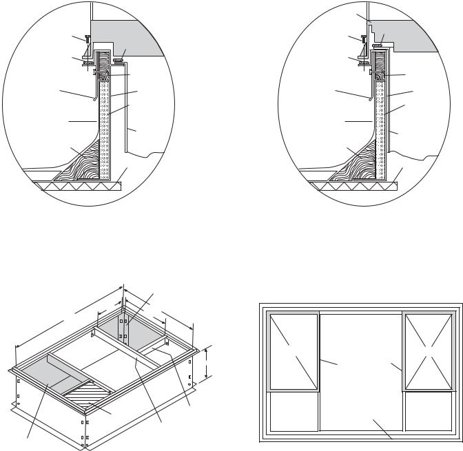
Supply opening (B x C)
BTyp. |
D |
44 5/16" |
CTyp. |
|
A
Short
Insulated deck pan
Support
Long
Support
Return opening (B X C)
R/A |
S/A |
|
Gasket around |
|
duct |
Insulated |
Gasket around |
deck pan |
outer edge |
|
C00076 |
UNIT SIZE |
ODS CATALOG NUMBER |
A |
B |
C |
D |
||
IN. (MM) |
IN. (MM) |
IN. (MM) |
IN. (MM) |
||||
|
|
|
|||||
50GS018-042 |
50GX024-036 |
CPRFCURB006A00 |
8 (203) |
11(279) |
16-1/2 (419) |
28-3/4 (730) |
|
CPRFCURB007A00 |
14 (356) |
11(279) |
16-1/2 (419) |
28-3/4 (730) |
|||
|
|
||||||
50GS048-060 |
50GX042-060 |
CPRFCURB008A00 |
8 (203) |
16-3/16 (411) |
17-3/8 (441) |
40-1/4 (1022) |
|
CPRFCURB009A00 |
14 (356) |
16-3/16 (411) |
17-3/8 (441) |
40-1/4 (1022) |
|||
|
|
||||||
NOTES:
1.Dimensions in ( ) are in millimeters.
2.Roof curb is made of 16-gage steel.
3.Table lists only the dimensions per part number that have changed
4.Insulated panels: 1-in. thick fiberglass 1 lb. density.
Fig. 4A— Roof Curb Dimensions
→
5

1 |
2 |
y
|
|
|
4 |
|
|
x |
|
|
|
3 |
|
|
|
|
||
|
|
|
|
|
|
|
|
|
|
|
|
|
|
|
|
C00071 |
|
|
|
|
|
|
|
|
|
|
|
|
|
|
|
|
|
CORNER # |
|
|
|
|
50GS |
|
|
|
|
|
|
|
50GX |
|
|
|
|
|
|
|
|
|
|
|
|
|
|
|
|
|
|
|
|
018 |
024 |
|
030 |
036 |
042 |
048 |
060 |
024 |
030 |
|
036 |
|
042 |
048 |
060 |
|
|
|
|
|
|||||||||||||
1 |
58 |
60 |
|
59 |
62 |
76 |
69 |
84 |
76 |
84 |
|
85 |
|
71 |
78 |
85 |
2 |
47 |
50 |
|
48 |
50 |
50 |
45 |
54 |
49 |
60 |
|
60 |
|
55 |
56 |
66 |
|
|
|
|
|
|
|
|
|
|
|
|
|
|
|
|
|
3 |
55 |
56 |
|
56 |
58 |
71 |
88 |
106 |
57 |
61 |
|
64 |
|
85 |
80 |
108 |
|
|
|
|
|
|
|
|
|
|
|
|
|
|
|
|
|
4 |
94 |
94 |
|
95 |
98 |
97 |
122 |
145 |
88 |
86 |
|
90 |
|
110 |
112 |
140 |
TOTAL WEIGHT |
254 |
260 |
|
258 |
268 |
294 |
324 |
389 |
270 |
291 |
|
299 |
|
321 |
326 |
399 |
|
|
|
|
|
|
|
|
|
|
|
|
|
|
|
|
|
Fig. 4B—50GS and 50GX Unit Corner Weights
A |
|
|
C |
|
|
|
|
|
MAXIMUM ALLOWABLE |
||
|
|
|
DIFFERENCE (in.) |
||
|
B |
|
|
|
|
|
A-B |
B-C |
A-C |
||
|
|
|
|||
|
|
|
|
|
|
|
|
|
1/4 |
1/4 |
1/4 |
C99065
Fig. 5A—Unit Leveling Tolerances
OPTIONAL |
OPTIONAL |
RETURN |
SUPPLY |
AIR |
AIR |
OPENING |
OPENING |
2" |
|
EVAP. COIL |
COND. COIL |
C99096
Fig. 5B—Slab Mounting Detail
6
914-137" (36"-54")
“A”
“B”
DETAIL A
SCALE 0.250
|
|
|
|
|
|
TIGHTEN STRAPPING SECURELY |
|
|
|
||
|
|
|
|
|
|
WITH TENSION BUCKLE |
|
|
|
||
|
|
|
|
|
INSTALL SAFETY STRAPS TO |
|
|
|
|
||
|
|
|
|
|
RIGGING CLEVIS AT 4 RIGGING BRACKETS |
|
|
|
|||
|
|
|
|
PLACE RIGGING BRACKET ASSEMBLY IN 4 |
|
|
|
|
|||
|
|
|
|
RIGGING HOLES AND INSTALL TIE DOWN STRAP |
|
|
|
|
|||
|
|
|
|
AROUND PERIMETER OF UNIT AND THROUGH |
|
|
|
|
|||
|
|
SEE DETAIL A |
SPACE IN BRACKET ASSEMBLY |
|
|
|
|
||||
|
|
|
|
|
|
|
|
|
C99066 |
||
|
|
|
|
|
|
|
|
|
|
|
|
|
|
|
|
|
|
|
|
|
|
|
|
SIZE |
|
MAXIMUM WEIGHT |
|
A |
|
|
B |
||||
lb. |
|
|
kg |
|
in. |
|
mm. |
in. |
|
mm. |
|
|
|
|
|
|
|
||||||
|
|
|
|
|
UNIT 50GS |
|
|
|
|
||
018 |
276 |
|
|
125.2 |
|
20 |
|
508.0 |
13 |
|
330.2 |
024 |
282 |
|
|
127.9 |
|
19 |
|
482.6 |
13 |
|
330.2 |
030 |
280 |
|
|
127.0 |
|
19 |
|
482.6 |
14 |
|
355.6 |
036 |
290 |
|
|
131.5 |
|
20 |
|
508.0 |
14 |
|
355.6 |
042 |
316 |
|
|
143.3 |
|
19 |
|
482.6 |
14 |
|
355.6 |
048 |
346 |
|
|
156.9 |
|
20 |
|
508 |
17 |
|
431.8 |
060 |
411 |
|
|
186.4 |
|
19 |
|
482.6 |
16 |
|
406.4 |
|
|
|
|
|
UNIT 50GX |
|
|
|
|
||
024 |
292 |
|
|
132.5 |
|
18.5 |
|
469.9 |
14.50 |
|
368.3 |
030 |
313 |
|
|
142.5 |
|
19.5 |
|
495.3 |
15.50 |
|
393.7 |
036 |
321 |
|
|
145.6 |
|
19.5 |
|
495.3 |
15.25 |
|
387.4 |
042 |
343 |
|
|
155.6 |
|
20.5 |
|
520.7 |
16.75 |
|
425.5 |
048 |
348 |
|
|
157.9 |
|
19.5 |
|
495.3 |
17.62 |
|
447.6 |
060 |
421 |
|
|
191.0 |
|
20.5 |
|
520.7 |
16.25 |
|
412.8 |
Fig. 6—Suggested Rigging
Lifting point should be directly over the center of gravity for the unit.
Step 6—Connect Condensate Drain
NOTE: When installing condensate drain connection be sure to comply with local codes and restrictions.
Models 50GS and 50GX dispose of condensate water through a 3/4 in. NPT fitting which exits through the base on the evaporator coil access side. See Fig. 2 & 3 for location.
Condensate water can be drained directly onto the roof in rooftop installations (where permitted) or onto a gravel apron in groundlevel installations. Install a field-supplied condensate trap at end of condensate connection to ensure proper drainage. Make sure that the outlet of the trap is at least 1 in. lower than the drainpan condensate connection to prevent the pan from overflowing (See Fig. 7). When using a gravel apron, make sure it slopes away from the unit.
Connect a drain tube using a minimum of 3/4 -in. PVC or 3/4 -in. copper pipe (all field-supplied) at the outlet end of the 2-in. trap.
Do not undersize the tube. Pitch the drain tube downward at a slope of at least 1-in. for every 10 ft. of horizontal run. Be sure to check the drain tube for leaks. Prime trap at the beginning of the cooling season start-up.
Step 7—Install Duct Connections
The unit has duct flanges on the supplyand return-air openings on the side and bottom of the unit. For downshot applications the ductwork can be connected to the roof curb. See Fig. 2 & 3 for connection sizes and locations.
IMPORTANT: Use flexible connectors between ductwork and unit to prevent transmission of vibration. Use suitable gaskets to ensure weathertight and airtight seal. When electric heat is installed, use fire proof canvas (or similar heat resistant material) connector between ductwork and unit discharge connection. If flexible duct is used, insert a sheet metal sleeve inside duct. Heat resistant duct connector (or sheet metal sleeve) must extend 24-in. from the unit discharge connection flange into the ductwork.
7

Table 1—Physical Data—Unit 50GS
UNIT SIZE |
018 |
024 |
030 |
|
036 |
042 |
048 |
060 |
NOMINAL CAPACITY (ton) |
1-1/2 |
2 |
2-1/2 |
|
3 |
3-1/2 |
4 |
5 |
OPERATING WEIGHT (lb.) |
254 |
260 |
258 |
|
268 |
294 |
324 |
389 |
COMPRESSOR |
|
|
Reciprocating |
|
|
Scroll |
Reciprocating |
|
REFRIGERANT (R-22) |
2.6 |
3.5 |
3.65 |
|
4.4 |
6.4 |
5.1 |
7.4 |
Quantity (lb.) |
|
|||||||
|
|
|
|
|
|
|
|
|
REFRIGERANT METERING DEVICE |
|
|
|
|
Accurater |
|
|
|
Orifice ID (in.) |
.034 |
.034 |
.034 |
|
.032 |
.034 |
.032 |
.030 |
|
|
|
|
|
|
|
|
|
CONDENSER COIL |
1...17 |
1...17 |
1...17 |
|
1...17 |
1...17 |
1...17 |
2...17 |
Rows...Fins/in. |
|
|||||||
6.1 |
9.1 |
9.1 |
|
10.9 |
9.1 |
12.3 |
12.3 |
|
Face Area (sq. ft.) |
|
|||||||
|
|
|
|
|
|
|
|
|
CONDENSER FAN |
2000 |
2400 |
2400 |
|
3000 |
3000 |
3600 |
3600 |
Nominal Cfm |
|
|||||||
22 |
22 |
22 |
|
18 |
22 |
22 |
22 |
|
Diameter |
|
|||||||
1/8 (825) |
1/8 (825) |
1/8 (825) |
|
1/4 (1100) |
1/4 (1100) |
1/4 (1100) |
1/4 (1100) |
|
Motor Hp (Rpm) |
|
|||||||
|
|
|
|
|
|
|
|
|
EVAPORATOR COIL |
2...15 |
2...15 |
2...15 |
|
3...15 |
4...15 |
3...15 |
4...15 |
Rows...Fins/in. |
|
|||||||
3.1 |
3.1 |
3.7 |
|
3.06 |
3.06 |
4.7 |
4.7 |
|
Face Area (sq. ft.) |
|
|||||||
|
|
|
|
|
|
|
|
|
EVAPORATOR BLOWER |
600 |
800 |
1000 |
|
1200 |
1400 |
1600 |
2000 |
Nominal Airflow (Cfm) |
|
|||||||
10x10 |
10x10 |
10x10 |
|
11x10 |
11x10 |
11x10 |
11x10 |
|
Size (in.) |
|
|||||||
1/4 (825) |
1/4 (1075) |
1/4 (1075) |
|
1/2 (1075) |
3/4 (1075) |
3/4 (1075) |
1.0 (1100) |
|
Motor HP (RPM) |
|
|||||||
|
|
|
|
|
|
|
|
|
RETURN-AIR FILTERS (in.)* |
20x20 |
20x20 |
20x20 |
|
20x24 |
20x24 |
24x30 |
24x30 |
Throwaway |
|
|||||||
|
|
|
|
|
|
|
|
|
* Required filter sizes shown are based on the larger of the ARI (Air Conditioning and Refrigeration Institute) rated cooling airflow or the heating airflow velocity of 300 ft./min. for throwaway type or 450 ft./min. for high-capacity type. Air filter pressure drop for non-standard filters must not exceed 0.08 in. wg.
Table 2—Physical Data—Unit 50GX
UNIT SIZE |
024 |
030 |
036 |
|
042 |
048 |
060 |
NOMINAL CAPACITY (ton) |
2 |
2-1/2 |
3 |
|
3-1/2 |
4 |
5 |
OPERATING WEIGHT (lb.) |
270 |
291 |
299 |
|
321 |
326 |
399 |
COMPRESSOR |
|
|
|
Scroll |
|
|
|
REFRIGERANT (R-22) |
3.7 |
4.4 |
5.2 |
|
7.6 |
8.3 |
8.1 |
Quantity (lb.) |
|
||||||
|
|
|
|
|
|
|
|
REFRIGERANT METERING DEVICE |
|
|
Accurater |
|
|
||
Orifice ID (in.) |
.034 |
.030 |
.032 |
|
.034 |
.034 |
.032 |
CONDENSER COIL |
1...17 |
1...17 |
2...17 |
|
2...17 |
2...17 |
2...17 |
Rows...Fins/in. |
|
||||||
10.8 |
12.7 |
9.1 |
|
9.1 |
12.3 |
16.4 |
|
Face Area (sq. ft.) |
|
||||||
|
|
|
|
|
|
|
|
CONDENSER FAN |
2350 |
2350 |
2350 |
|
3300 |
3300 |
3300 |
Nominal Cfm |
|
||||||
22 |
22 |
22 |
|
22 |
22 |
22 |
|
Diameter (in.) |
|
||||||
1/8 (825) |
1/8 (825) |
1/8 (825) |
|
1/4 (1100) |
1/4 (1100) |
1/4 (1100) |
|
Motor Hp (Rpm) |
|
||||||
|
|
|
|
|
|
|
|
EVAPORATOR COIL |
3...15 |
3...15 |
3...15 |
|
3...15 |
4...15 |
4...15 |
Rows...Fins/in. |
|
||||||
3.1 |
3.1 |
3.7 |
|
4.7 |
4.7 |
4.7 |
|
Face Area (sq. ft.) |
|
||||||
|
|
|
|
|
|
|
|
EVAPORATOR BLOWER |
800 |
1000 |
1200 |
|
1400 |
1600 |
1750 |
Nominal Airflow (Cfm) |
|
||||||
10x10 |
10x10 |
11x10 |
|
11x10 |
11x10 |
11x10 |
|
Size (in.) |
|
||||||
1/4 (1075) |
1/4 (1075) |
1/2 (1075) |
|
3/4 (1075) |
3/4 (1075) |
1.0 (1040) |
|
Motor Hp (RPM) |
|
||||||
|
|
|
|
|
|
|
|
RETURN-AIR FILTERS (in.)* |
20x20 |
20x20 |
20x24 |
|
20x30 |
24x30 |
24x30 |
Throwaway |
|
||||||
|
|
|
|
|
|
|
|
*Required filter sizes shown are based on the larger of the ARI (Air Conditioning and Refrigeration Institute) rated cooling airflow or the heating airflow velocity of 300 ft./min. for throwaway type or 450 ft./min. for high-capacity type. Air filter pressure drop for non-standard filters must not exceed 0.08 in. wg.
CONFIGURING UNITS FOR DOWNFLOW (VERTICAL) DISCHARGE
Before performing service or maintenance operations on the system, turn off main power to unit and install lockout tag or electrical shock could result.
1.Open all electrical disconnects and install lockout tag before starting any service work.
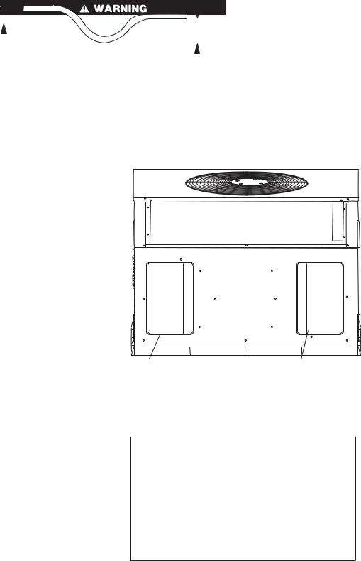
2. Remove return duct cover located on duct panel by breaking four (4) connecting tabs with screwdriver and a hammer. (Fig. 8 & 9)
3. To remove supply duct cover, break front and right side connecting tabs with a screwdriver and a hammer. Push louver down to break rear and left side tabs. (Fig. 8 & 9)
4. If unit ductwork is to be attached to vertical opening flanges on the unit composite base (jackstand applications only), do so at this time. Collect ALL screws that were removed. Do not leave screws on rooftop as permanent damage to the roof may
occur.
8
1” (25mm) MIN.
|
|
|
|
|
|
|
|
|
|
TRAP |
|
|
|
|
|
|
|
|
|
|
|
|
|
|
|
OUTLET |
|
|
|
|
|
|
|
|
|
|
|
|
|
|
|
|
|
|
|
|
|
|
|
|
|
|
|
|
|
|
|
|
|
|
|
|
|
|
|
|
|
|
|
|
|
|
|
|
|
|
|
|
|
|
|
|
|
|
|
|
|
|
|
|
2” (50mm) MIN. |
C99013 |
|||
|
|
|
|
|
|
|
|
|
|
|
|||||
|
|
|
|
|
|
|
|
|
|
|
|||||
|
|
|
|
|
|
|
|
|
|
|
|
|
|
|
|
|
|
|
|
|
|
|
|
|
|
|
|
|
|
|
|
|
|
|
|
|
Fig. 7—Condensate Trap |
|
|
|
|
||||||
|
|
|
|
|
|
|
|
|
|||||||
|
|
|
|
|
|
|
|
|
|||||||
|
|
|
|
|
|
|
|
|
|
||||||
|
|
Table 3—Minimum Airflow for Safe Electric Heater |
|
||||||||||||
|
|
|
|
|
|
Operation (Cfm) |
|
|
|
|
|
|
|||
|
|
|
|
|
|
|
|
|
|
|
|
|
|
||
|
|
|
|
|
|
SIZE |
|
|
|
|
|
|
|||
018 |
024 |
|
030 |
|
036 |
|
042 |
|
048 |
060 |
|||||
700 |
800 |
|
1000 |
|
1200 |
|
1400 |
|
1600 |
2000 |
|||||
|
|
|
|
|
|
|
|
|
|
|
|
|
|
|
|
5.It is recommended that the unit base insulation around the perimeter of the vertical return-air opening be secured to the unit base with aluminum tape. Applicable local codes may require aluminum tape to prevent exposed fiberglass.
6.Cover both horizontal duct openings with the duct covers from the accessory duct cover kit. Ensure opening is air-and watertight.
7.After completing unit conversion, perform all safety checks and power up unit.
NOTE: The design and installation of the duct system must be in accordance with the standards of the NFPA for installation of nonresidence-type air conditioning and ventilating systems, NFPA 90A or residence-type, NFPA 90B; and/or local codes and ordinances.
Adhere to the following criteria when selecting, sizing, and installing the duct system:
8.Units are shipped for side shot installation.
9.Select and size ductwork, supply-air registers, and return-air grilles according to American Society of Heating, Refrigeration and Air Conditioning Engineers (ASHRAE) recommendations.
10.Use flexible transition between rigid ductwork and unit to prevent transmission of vibration. The transition may be screwed or bolted to duct flanges. Use suitable gaskets to ensure weathertight and airtight seal.
11.All units must have field-supplied filters or accessory filter rack installed in the return-air side of the unit. Recommended sizes for filters are shown in Tables 1 and 2.
12.Size all ductwork for maximum required airflow (either heating or cooling) for unit being installed. Avoid abrupt duct size increases or decreases or performance may be affected.
13.Adequately insulate and weatherproof all ductwork located outdoors. Insulate ducts passing through unconditioned space, and use vapor barrier in accordance with latest issue of Sheet Metal and Air Conditioning Contractors National Association (SMACNA) and Air Conditioning Contractors of America (ACCA) minimum installation standards for heating and air conditioning systems. Secure all ducts to building structure.
14.Flash, weatherproof, and vibration-isolate all openings in building structure in accordance with local codes and good building practices.
SUPPLY |
RETURN |
DUCT |
DUCT |
OPENING |
OPENING |
C99011
Fig. 8—Supply and Return Duct Opening
Step 8—Install Electrical Connection
The unit cabinet must have an uninterrupted, unbroken electrical ground to minimize the possibility of personal injury if an electrical fault should occur. This ground may consist of an electrical wire connected to the unit ground lug in the control compartment, or conduit approved for electrical ground when installed in accordance with NEC (National Electrical Code) ANSI/NFPA (latest edition) and local electrical codes. In Canada, follow Canadian Electrical Code CSA (Canadian Standards Association) C22.1 and local electrical codes. Failure to adhere to this warning could result in personal injury or death.
9
 Loading...