


50EQ
Table of contents
 Loading...
Number One
AirConditbning
l\Mer
Division of
Carrier Corporation
Carrier Parkway • Syracuse, N Y 13221
Single-Package Heat Pumps
INSTALLATION
Rigging and Unit Placement — Inspect unit for
transportation damage. File claim with transporta
tion agency. Do not drop unit. Keep unit upright.
Units are designed to be hoisted only. However,
units with optional shipping skids may be moved
with a fork truck. Use spreader bars over unit to
prevent sling or cable damage to unit. Level unit by
using unit frame as reference. Leveling tolerance is
± 1 /16 in. per linear ft in any direction. See Fig. 1 for
additional information. Unit weight is shown in
Table 1.
Roof Curb — Assemble and install accessory roof
curb in accordance with instructions shipped with
accessory. (In areas of prolonged sub-freezing tem
peratures or heavy snowfall, the use of an 18-in.
high roof curb is recommended. This permits proper
drainage during defrost.) Refer to Fig. 2.
Install insulation, cant strips, roofing and flashing
as required. Ductwork can be installed to roof curb
«OTES;
t, A!i BTift (lanets jnust be in piece when rtg8^ns
2. Oo not bandte unit wsdi 'torit iruciis.
3. Use4«ei)}esan«i4"24>y-4Vor "4-by-4V'of ctenenaons
shown.
© Carrier Corporation 1979
Fig. 1 — Rigging Details
before unit is set in place. Curb should be level. Unit
leveling tolerance is ±1/16 in. per linear ft in any
direction. This is necessary to permit unit drain to
function properly.
Cut hole(s) in roof to accommodate return and
supply ducts only. Refer to accessory installation
instructions.
Roof Mount — Check building codes for weight
distribution requirements.
Alternate Unit Support Methods — Where the
preferred curb or slab mount cannot be used, sup
port unit with sleepers along unit perimeter using
unit curb-support areas. However, if sleepers cannot
be used, support long sides of unit (dimension “A,”
Fig. 3) by three 4-in. by 4-in. pads, equally spaced.
Units may sag if supported by corners only.
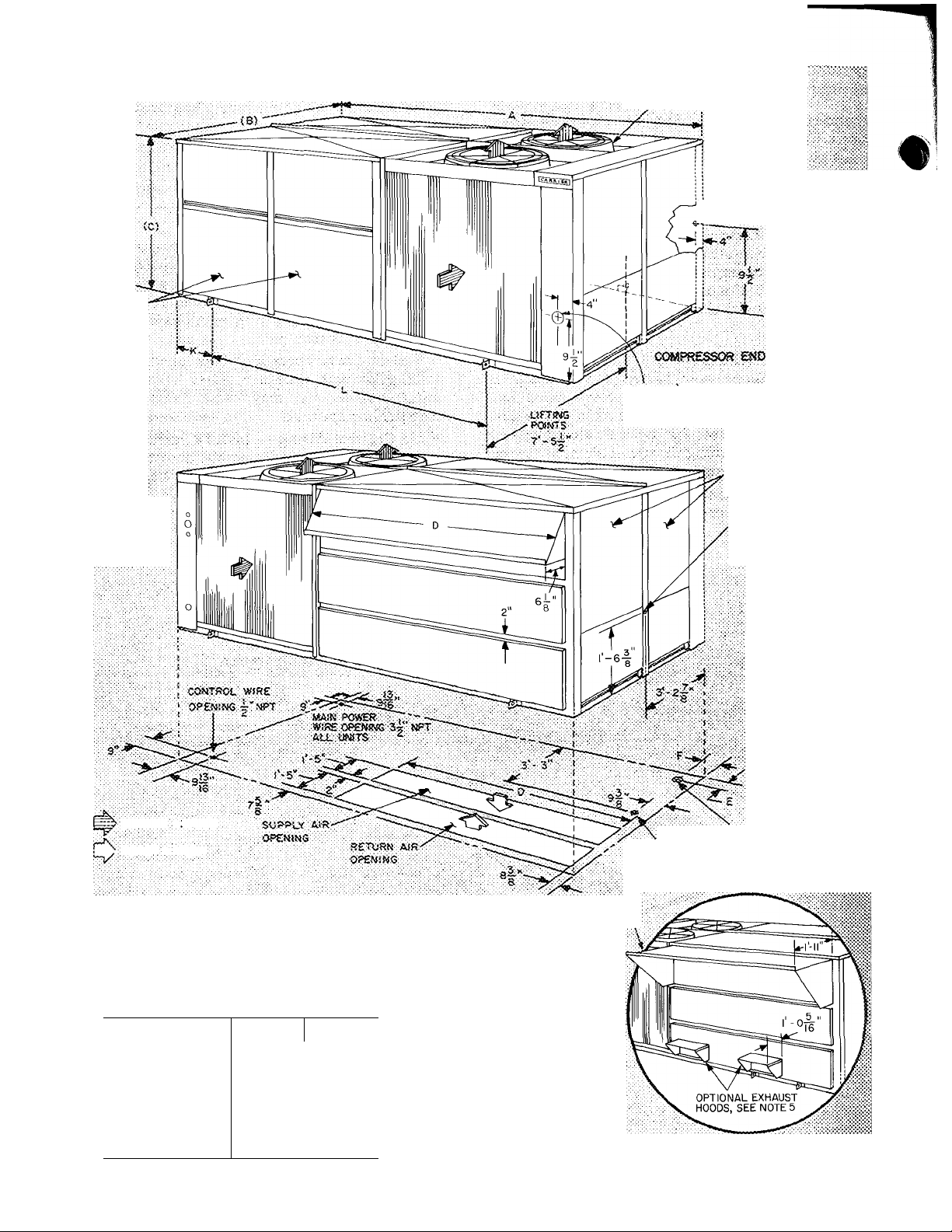
Positioning — Position unit so that drifting snow
does not build up on outdoor coil. Provide clear
ances around and above the unit for airflow, safety,
and service access (Fig. 3).
Do not install unit in an indoor location. Do not
locate unit air inlets near exhaust vents or other
sources of contaminated air.
Although unit is weatherproof, guard against
water from higher runoff and overhangs.
Field-Fabricated Ductwork — Secure all ducts to
building structure. Use flexible duct connectors be
tween unit and ducts as required. Insulate and
weatherproof all external ductwork, joints and all
roof openings with flashing and mastic in accord
ance with applicable codes.
Ducts passing thru unconditioned spaces must be
insulated and covered with a vapor barrier.
Unit Duct Connections — Ductwork openings
are shown in Fig. 3.
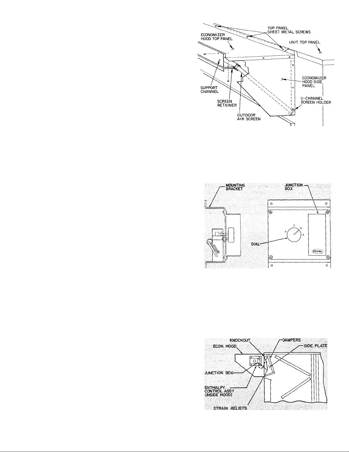
Economizer Hood Installation, Fig. 4 — The
economizer mechanism and allelectrical connections
are factory installed and adjusted. The hood assem
bly, outdoor air inlet screens and required hardware
are shipped separately and must be field installed.
NOTE: There is a linkage rod and 3 fasteners (speed
nuts) shipped with the economizer hood assembly.
This rod is not required on 50EQ units.
Install economizer hood(s) as follows:
1. Loosen unit top panel sheet metal screws above
outdoor air inlet opening.
2. Assemble hood top panel, side panels and
support channel.
Form 50EQ-4SI

Table 1 — Physical Data
UNIT MODEL
50EQ024
50EQ028
50EQ034
OPERATING WEIGHT (lb)
Base Unit
3300
3900
4550
Base Unit with Economizer
3450
4075
4750
COMPRESSOR
Serviceable, Reciprocating Hermetic
No. .Model
2 06D824
2. 06D328
2 06D537
Oil (3GS or B1) pts (per Compr) 10
10
10
REFRIGERANT CHARGE R-22
R-22
—
Sys 1*...Sys 2 (lb)
20.0...21.3
23.5..24.0
29.1..29.1
OUTDOOR AIR FANS
Direct Drive, Propeller
No. ...Hp
2 . 1
2 . 1
3 1
Frame (NEMA)
56T
56T
56T
Rpm (1-Phase)
1050
1050
1050
IIMDOOR AIR FANS
Motor
Shaft Diam (in.) — RPM 1750
Motor Frame Size
Motor Pulley Pitch Diam (in.)t
Fan Pulley Pitch Diam (in.)
Fan Speed (rpm)
Fan Shaft Diam (in )
Belt No. ...Size
Std
Opt
Std
Opt
Std
Opt
Std, A,B
Opt, A,B
Std
Opt
Std, A,B
Opt, A,B
Std
Opt
5
7-1/2
1-1/8
1-3/8
1S4T
213T
6 5 6 0
5 3 5 6
106
8
1073 991
1159 1225
1-3/16
2 3V750
2 3V670
1300
Fixed Speed Centrifugal
7-1/2
10
1-3/8
1-3/8
213T
215T
6 5 60
5 6 60
10 6
8
1073 991
1225 1312
1-3/16
2 3V750
2 3V670
1300
ELECTRIC HEATERS
Heat Anticipator Setting
Stage 1 ...2
9 25
9 25
9 25
HIGH-PRESSURE SWITCH
Cutout (psig)
Cut-in (psig)
428
320
428
320 ± 20
428 .jQ
320
LOW-PRESSURE SWITCH
Cutout (psig) 5+3
5 ± 3
5 + 3
Cut-in (psig) 20 ± 5
20 ± 5
20 + 5
INDOOR AIR FILTERS (2-in.)
Standard; No. ...Size (in.)
Throwaway; No. ...Size (in.)
6 20x25
6. .16x25
18 16x25
9 20x25
12 16x25
AIR INLET SCREENS
Manual Damper; No. ...Size (in.)
_
Economizer; No. .. Size (in.)
3 20x25
4 20x25
5 20x25
10
15
1-3/8
1-5/8
215T
254T
6 5 5 6
5 3 5 6
10 6
8
1073 925
1159 1225
1-11/16
2 3V750
4 3V710
1300
*System No 1 is bottom portion of indoor coil
fStandard fan motor supplied with standard fan drive pulleys and belts, optional fan motor supplied with optional
fan drive pulleys and belts Pulley A is installed in unit; pulley B is shipped with unit
3. Insert hood flange between unit top panel flange
and unit. Slots are provided in hood flange to
clear sheet metal screws. Tighten sheet metal
screws.
4. Secure hood side panels to outdoor air opening
flanges using screws provided.
5. Install hood support bracket(s) between U-
channel and support channel.
6. Install screen retainer on support channel using
screws in the slots. Do not tighten.
7. Install outdoor air screens.
8. Push retainers snugly against screens and tighten
screws.
Enthalpy Control — Remove enthalpy control
assembly (Fig. 5) from shipping location on hori
zontal deck in return air filter compartment.
Using 4 no. 10-1 /2 screws from envelope in con
trol assembly junction box, mount the enthalpy con
trol assembly to the inside of economizer hood side
panel nearest condenser section (Fig. 6).
Route the 3 wires, coiled near top cover on the
condenser partition, thru knockout in side plate
(Fig. 6). Using wire connectors from envelope in
junction box, wire enthalpy control assembly as
shown in Fig. 7. Use strain reliefs from envelope in
junction box on side plate and junction box (Fig. 6).
Exhaust Air Hood Installation — The optional
power exhaust package hood assemblies and re
quired sheet metal screws are shipped in compart
ment at right of indoor air fan motor.
Using screws provided, install a hood assembly
over each exhaust air opening as shown in Fig. 3.
Power exhaust applies only to units with econo
mizer. The exhaust fan and motor assembly is
factory wired and adjusted. Refer to Service, Ex
haust Air Fan Adjustment if required.
Return Air Filters — Check to be sure return air
filters of the correct type and size are installed in
unit filter racks. Filter data is shown in Table 1. Do
not operate unit without return air filters.

Outdoor Air Inlet Screens — Be sure all outdoor
air inlet screens are in place before operating unit.
Condensate Drains — See Fig. 3 for drain loca
tions. Condensate drain is open to atmosphere and
must be trapped. Install a trapped drain line at con
nection to be used. Trap must be at least 4 in. deep
and made of flexible material or be installed so as
to prevent freeze-up.
Condensate drain pan is fitted with a 1-in. FPT
coupling. Condensate drain line may be routed thru
unit base pan or unit side as shown. A grommet is
shipped taped to this drain. Install this gasket in unit
base pan opening or alternate opening on end of unit
as required.
Field Power Wiring — All units have circuit
breakers for compressors, heaters, fan motors and
control circuits. Each unit is factory wired for
voltage shown on nameplate. The main power ter
minal block is suitable for use with aluminum or
copper wire. See Table 2 for use of aluminum wire
on electric heater terminal blocks.
Install conduit connections in unit base pan or
side panel opening provided as shown in Fig. 3.
On all units route power lines to terminal block in
control box as shown in Fig. 8. On units with electric
heat, route second power supply line thru connector
to terminal block in heater compartment.
Locate field-supplied disconnect(s) within sight of
and directly accessible from the unit. All field wiring
must comply with NEC and local requirements.
Affix crankcase heater sticker to unit disconnect
switch.
Voltage to compressor terminals during com
pressor operation must be within voltage range indi
cated on unit nameplate. Phases must be balanced
within 2%. Contact local power company for
correction of improper voltage or phase imbalance.
See Table 2 as required.
Failure due to operation of unit on improper line
voltage or with excessive phase imbalance con
stitutes abuse and may cause damage to unit
electrical components.
Field Control Wiring — Install a Carrier approved
accessory thermostat assembly according to in
stallation instructions included with the accessory.
Locate thermostat assembly in the conditioned
space where it will sense average temperature.
DIMENSIONS (ft-in.)
UNIT
ROOF CURB
MODEL NO.
A
B
C
D E F
50EQ024
50EQ900001
10- Cfl/4 4-11
—
0-6-1/4
0-5-1/8
50EQ028 50EQ900011
12-10-3/4
6-11
—
—
0-6-1/4Ì0-5-1/8
50EQ034
50EQ900021
16- 3-1/8 9- 0
4-4
0-6
0-6-1/4 0-5-7/8
NOTES
1 Certified dimension drawings are available on
req uest
2. For details of 12-in high roof curb, refer to 48DD
roof curb installation instructions
3. Two field power supplies are required for 50EQ
units with electric heat
Fig. 2 — Roof Curb Dimensions
3
st.ecT!îtc
f£ATE=i
ACCESS
PANELS
3 mo 4^ • K 0
AlTERKATE R1EL&-P0ȣR WiRlNG
ALL. l»f:TS
!NDOORA>!ifAN
AMD «LTEft
ACCESS PA MELS
ALTERMATE
CO'iTRCl. A'-SE
^OPEMiNG A-'CDNOmT
COMPRESSOR
END
ACTES-yJATE
DRAÎÎi 2|''iCO-ÎÎ'VPr
COiWi miDE)
OL'TCXÎOR A'RPLO'#
- iMOOOSr AiftELOW
Certt^,«cf dimecswR <lf3w»i>gs avaiîab!« on recjwesi.
DRAIN :
sl^OiAMit"
'■mPT conn. fNSiOEÏ
POWER WISE CPQiii«® m
EtSCTRK tCAT 0«t,V
DiMENSiONS {ft-'jn.)
UNÎT
50EQ
024
028
034
A \ Î0- 9-13''f6 13- S^1/2
: 17- 1
8
5 7- 2-1Î/16 7- 3-1/8
: 7- 3-1/8
C
1 4-10-1/2 4-10-1/2
4-10-1/2
D
? 4-11 S-11
■ 11- 0
E
I 0-10-1/4
0-10-1/4
: 0-10-1/4
F : 0- 9-7/8 0- S-7/S : C- 9-7/8
6
■ > ■ ■■ • ■ — ■■
..
■
H
1
J
: 3-1/2" N-PT
4“ NPT
; 4" MPT
K j 2- A
...;2-.:4:.:v:
i 2-10
L
; 6- 1-V2 9- 0 ■ 11- 5
CPTlOKAi.
ECOfJOMSZER HOOO
Mcrrss.
■J Aiiow 12 ft at>ove ar»t^ S ft on
f iher access panel encf and 4 ft on
fenjatnfns sfdesof unttforairfiow
attd service clearance.
2, for smaller ciearances. contact
Carrier.
3. Refer to Roof Curb Dmrensions
for details of roof openings.
4, The 50EO034ut«t contains ittree
fans.
5. Tfte50EQ034 unit contains tnree
exhaiist hoods.
€
Fig. 3 — Base Unit Dimensions
Route thermostat cable or equivalent single leads
of no. 18 AWG colored wire from subbase terminals
thru connectors in unit base pan or side panel (Fig.
3) to low-voltage connections in control box as
shown in Fig. 9. Use no. 16 AWG wire for lengths
exceeding 50 feet. Set heat anticipator settings as
indicated in Table 1.
Refer to accessory remote control panel instruc
tions as required.
Outdoor Air Thermostat — Unit is equipped with
a field adjustable outdoor air thermostat. Thermo
stat is shipped taped to right-hand side of unit
control box. Upon start-up, set the thermostat
“close setpoint” to the building load balance point
and unit capacity. Above the setpoint, the space
thermostat controls 2 stages of compression heat
and electric heat is locked out. Below the setpoint,
one stage of compression heat is available and elec
tric heat is controlled by the second stage of the
space thermostat.
Compressor(s) — Loosen compressor hold-down
bolts until sidewise movement of the washer under
each hold-down bolt head can be easily obtained.
Do not loosen completely as bolts are self-locking
and will maintain their adjustment.
Open the compressor discharge and suction
service valves. Replace and tighten valve caps to
prevent leaks.
Liquid Line Service Valves — Open the liquid line
service valves. Replace caps and tighten to prevent
leaks.
START-UP
Cooling
1. Open compressor service valves. Replace valve
caps to prevent leaks. Make sure crankcase
heater has been on for at least 24 hours to
drive out any liquid refrigerant in compressor
crankcase. Check compressor oil level. Oil sight
glass should be about half full.
2. Be sure that liquid line service valve is open.
3. Check that setscrews are tight in fan bearing
locking collar, pulley and fan blades.
4. Check pulley alignment and belt adjustment.
Remove tape on indoor fan pulley.
5. Check that internal power wire terminal screw
connections are tight.
6. On 3-phase units, check for correct fan rotation.
7. Set system selector switch at COOL and fan
switch at AUTO. Adjust thermostat at a setting
below room temperature. Compressor no. 1 will
start on closure of no. 1 contactor. An addi
tional rise in room temperature closes cooling
contactor no. 2 in thermostat, energizing no. 2
contactor, no. 2 compressor will start.
8. Check cooling effect at duct supply outlets.
9. Check unit charge. Refer to Refrigeration
Charge in Service section.
Fig. 4 — Economizer Outdoor Air Inlet
Hood Assembly
Fig. 5 — Enthalpy Control Assembly
Fig. 6 — Enthalpy Control Assembly
Installation Details
Loading...