


50HJ015
Table of contents
 Loading...
HEATING & COOLING
50HJ015,024
Single-Package Rooftop Units
Electric Cooling with Electric Heat Option
Installation, Start-Up and Service
Instructions
CONTENTS
Page
SAFETY CONSIDERATIONS
INSTALLATION ................................................................. 1-9
Step 1 — Provide Unit Support.......................................... 1
• ROOF CURB
• ALTERNATE UNIT SUPPORT
Step 2 — Rig and Place Unit ............................................ 1
• POSITIONING
• ROOF MOUNT
Step 3 — Field Fabricate Ductwork
Step 4 - Make Unit Duct Connections .... 6
Step 5 — Trap Condensate Drain
Step 6 — Make Electrical Connections
• FIELD POWER SUPPLY
• FIELD CONTROL WIRING
Step 7 — Make Outdoor-Air Inlet
Adjustments......................................................................... 8
• MANUAL OUTDOOR-AIR DAMPER
• OPTIONAL FACTORY-INSTALLED
ECONOMIZER
Step 8 — Install Outdoor-Air Hood
START-UP....................................................................... 10-12
SERVICE
START-UP CHECKLIST...................................................CL 1
...........................................................................
...........................................
...............................
......................................
..............................
...................................
1
6
6
7
8
12-16
SAFETY CONSIDERATIONS
INSTALLATION
Step 1
ROOF CURB — Assemble and install accessory roof curb
in accordance with instructions shipped with the curb.
Accessory roof curb and information required to field
fabricate a roof curb are shown in Fig I and 2. Install in
sulation, cant strips, roofing, and counter flashing as shown.
Ductwork can be secured to roof curb before unit is set in
place.
IMPORTANT' The gasketing of the unit to the roof
curb is critical for watertightness Install gasket sup
plied with the roof curb as shown in Fig. 1. Improp
erly applied gasket can result in air leaks and poor
unit performance.
Curb should be level. This is necessary to permit unit
drain to function properly Unit leveling tolerance is
± Vi6 in. per linear ft in any direction. Refer to Accessory
Roof Curb Installation Instructions for additional informa
tion as required.
ALTERNATE UNIT SUPPORT - When the curb cannot
be used, support unit with sleepers using unit curb support
area. If sleepers cannot be used, support long sides of unit
with a minimum of 3 equally spaced 4-in. x 4-in. pads on
each side.
Provide Unit Support
Installation and servicing of air-conditioning equipment
can be hazardous due to system pressure and electrical com
ponents. Only trained and qualified service personnel should
install, repair, or service air-conditioning equipment.
Untrained personnel can perform basic maintenance func
tions of cleaning coils and filters and replacing filters. All
other operations should be performed by trained service
personnel. When working on air-conditioning equipment,
observe precautions in the literature, tags and labels at
tached to the unit, and other safety precautions that may
apply.
Follow all safety codes. Wear safety glasses and work
gloves. Use quenching cloth for unbrazing operations. Have
fire extinguishers available for all brazing operations.
A WARNING
Before performing service or maintenance operations
on unit, turn off main power switch to unit. Electrical
shock could cause personal injury.
Manufacturer reserves the right to discontinue, or change at any time, specifications or designs without notice and without incurring obligations.
BookII PC 111 Catalog No 565-125 Printed in U S A. Form 50HJ-6SI Pg 1 12-93 Replaces: New
Tab 1b
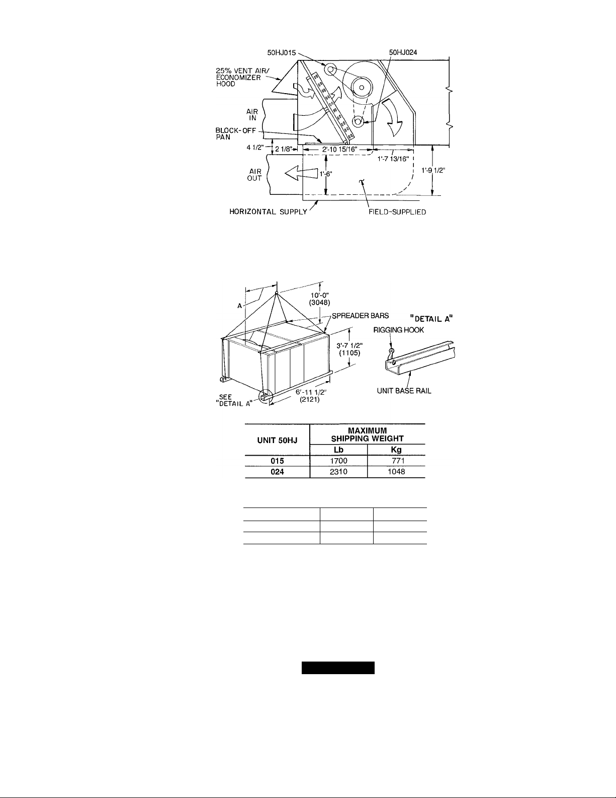
Step 2 — Rig and Place Unit — Inspect unit for
transportation damage. File any claim with transportation
agency. Keep unit upright, and do not drop. Use spreader
bars over unit to prevent sling or cable damage. Rollers
may be used to move unit across a roof. Level by using unit
frame as a reference; leveling tolerance is ± l/i6 in. per lin
ear ft in any direction. See Fig. 1 for additional leveling
tolerance information. Unit weight is shown in Table 1.
Four lifting holes are provided in ends of unit base rails
as shown in Fig. 3 Refer to rigging instructions on unit.
POSITIONING — Provide clearance around and above unit
for airflow, safety, and service access (Fig. 4).
Do not install unit in an indoor location. Do not locate
air inlets near exhaust vents or other sources of contam
inated air.
Although unit is weatherproof, guard against water from
higher level runoff and overhangs.
ROOF MOUNT — Check building codes for weight dis
tribution requirements.

NOM. 5/4 X 4
(32) X (102)
TYP 4 PLC5
0“
COMPR
SECT
1 -6
(50P0900151 ONLY) lb4)
OPENING
(457) . ^ .
SUPPLY
CURB
PLAN VIEW OF ROOF CURB
- ___
RETURN
OPEN(NG
CURB
OUTLINE
g
___________
OF UNIT
A (1753)
.Ü
INSULATED PANE', FOR SIDE
SUHPLY AND RETURN
(50P09001S1 ONLY)
5'-3'
UNIT OPENINGS
-(’so/)
1 t
SUPPLY AIR RETURN AIR
SECT ION A-A
GASKET
(SUPPLIED
WITH CURB)
COUNTER FLASHING
ROOFING FELT
(FIELD SUPPLIED)
. CANT STRIP
(FIELD SUPPLIED)
RIGID INSULATION
(FIELD SUPPLIED)
-1 -4 5/16
(415)
(FIELD SUPPLIED)
•ROOFING material
(FIELD SUPPLIED)
OPTIONAL
SIDE 5UPPLT
(305)
ATTACH DUCT TO ROOF CURB
ACCESSORY
PACKAGE NO.
50PQ900221
50PQ900141
50PQ900151
CURB
HEIGHT
V-2"
(305)
2'-0"
(610)
2'-0"
(610)
DESCRIPTION
Standard Curb —
14" High
Standard Curb
for Units Requiring
High Installation
Horizontal Supply
and Return Curb
LEGEND
COMP SECT. — Compressor Section
NOTES:
1 Roof curb accessory is shipped unassembled.
2. Insulated panels, 1-in thick neoprene-coated,
IV2 lb density.
3 Dimensions in ( ) are in millimeters.
4 Direction of airflow.
5 Roof curb 16 gage steel.
O’-S 3/16*'
&
0 32)
NOTE: To prevent the hazard of stagnant water build-up in the drain
pan of the indoor-air section, unit can only be pitched as shown.
Fig. 1 — Roof Curb Details
I
EVAPORATORFAN MOTOR
EVAPORATORFAN MOTOR
CURB (50P0900I5I)
TRANSITION DUCT
Fig. 2 — Horizontal Supply/Return Curb Details
DIMENSION A
UNIT 50HJ
015
024
Ft-in. mm
3-0 914
3-4’/2 1029
ÊJ
NOTES;
1. Dimensions in ( ) are in miilimeters
2 Refer to Tabie 1 for unit operating weights.
3. Remove boards at ends of unit and runners prior to rigging.
4 Rig by inserting hooks into unit base raiis as shown. Use corner
post from packaging to protect coii from damage. Use bumper
boards for spreader bars.
5 Weights do not inciude optionai economizer See Table 1 for econo
mizer weight.
6. Weights given are for aluminum evaporator coii plate fins and
copper condenser coii piate fins Weights of other metai combi
nations are listed in Table 1
A CAUTION
All panels must be in place when rigging.
Fig. 3 — Rigging Details

CONTROL BOX
ACCESS
•25% AIR On
''ECONOMIZER HOOD
pO -3 7/16'
i (87)
C
SECTION A-A
■ }
0’-3"
(76)
O'-l"
1(102)
I
UNIT
50HJ
015 390
024 492
‘Weights are for unit only (with aluminum evaporator and condenser
coil fins) and do not include options or crating
Lb
A
Kg
177
233
CORNER WEIGHT*
B
Lb
Kg
243 110 322 146
232
511
C D
Lb
Kg
504 229
Lb
Kg
515 234
523 237
Fig. 4 — Base Unit Dimensions
DIMENSIONS
UNIT
50HJ
A
Ft-in. mm Ft-in. mm
015 3-0
024 3-4% 1035 3-7
LEGEND
914
B C
838 1-10 559
2-9
1092 1-8 508
Ft-in. mm
KO — Knockout
NOTES;
1 Dimensions in ( ) are in millimeters
2- ® Center of gravity.
Direction of airfloiw.
Ductwork to be attached to accessory roof curb only.
Minimum clearance:
a Rear; 7'-0" (2134) for coil removal. This dimension
can be reduced to 4'-0" (1219) if conditions permit
coil removal from the top
Left side: 4'-0" (1219) for proper condenser coil
airflow
Front' 4'-0" (1219) for control box access
Right side: 4'-0" (1219) for proper operation of damper
and power exhaust (if so equipped).
e. Top: 6'-0" (1829) to assure proper condenser fan
operation.
f. Local codes or jurisdiction may prevail.
With the exception of clearance for the condenser coil
and the damper/power exhaust as stated In note no 5, a
removable fence or barricade requires no clearance
Dimensions are from outside of corner post. Allow
O'-Vie" (8) on each side for top cover drip edge
i

Table 1 — Physical Data
UNIT SIZE 50HJ
OPERATING WT (lb)
COMPRESSOR
REFRIGERANT
REFRIGERANT METERING DEVICE
CONDENSER COIL
CONDENSER FAN
EVAPORATOR COIL
EVAPORATOR FAN
HIGH-PRESSURE SWITCH
LOW-PRESSURE SWITCH
AIR INLET SCREENS
RETURN-AIR FILTERS (TYPE)
LEGEND
AI — Aluminum
Cu — Copper
'Evaporator coil fin material/condenser coil fin material.
tWeight of 14 in. roof curb.
"System 1 consists of the upper portion of condenser coil and intertwined evaporator coil, and
System 2 consists of the lower portion of the condenser coil and intertwined evaporator coil
NOTE: The 50HJ015 has adjustable pulleys The 50HJ024 has one set (2) of fixed pulleys
AI/AI*
Unit Al/Cu*
Cu/Cu*
Economizer
Roof Curbt
Number
Oil (oz)152
Charge (lb)** Sys 1, Sys 2
Upper Circuit
No. ...Length (in.)...iD/OD
Lower Circuit
No. ...Length (in.)...iD/OD
Rows
Fins/in.
Total Face Area (sq ft)
Nominal Cfm
Number...Diameter (in.)
Motor Hp (1075 Rpm)
Watts Input (Total)
Rows
Fins/in.
Total Face Area (sq ft)
Quantity...Size (in.)
Nominal Cfm
Maximum Allowable Rpm
Motor Pulley Pitch Diameter (in.)
Fan Pulley Pitch Diameter (in.)
Belt, Quantity...Type...Length (in.)
Factory Speed Setting (Rpm)
Motor Hp (Service Factor)
Motor Frame Size
Cutout (psig)
Reset (psig)_____________________
Cutout (psig)
Reset (psig)
Economizer, Quantity...Size (in.)
Quantity... Size (in.)
____________________
20.8,
6.. .25...0 055/0.125
6.. 25...0 055/0.125
6.. .25...0 055/0.125
Copper Tubes, Aluminum or Copper Plate Fins
13 6 Al or 12.4 Cu
18.9
12,000
2...26
1
2672
Copper Tubes, Aluminum or Copper Plate Fins
14.3 Al or 13.1 Cu
165
2.. 10 X 10
1 .V...41
2.. .20 X 20 X 2
3.. .16 X 20 X 2
2.. .16 X 25 X 2
Centrifugal, Fixed Pitch Belt Drive
5000
1550
3 4-4.4
6.0
1092
3 (1.15)
56
10% Efficient — 2-in Throwaway Fiberglass
R-22
I
Capillary Tubes
Propeller Type, Direct Drive
426
320
7
22
2 20 X 25 X 1
1 20 X 20 X 1
2030
2160
2270
110
200
16.25, 16.25
13. 25 .0.055/0.125
13...25.. 0.055/0 125
13.6 Al or 12.4 Cu
22 2
11,400
2 .26
1
3000
14.4 Al or 13.1 Cu
17.9
2...12 X 12
8000
1500
6.10
8.40
1. BX.. 51
1287
7V2 (1.15)
184T
4.. 20 X 20 X 2
4.. 16 X 20 X 2
Step 3 — Field Fabricate Ductwork — Secure all
ducts to building structure. Use flexible duct connectors be
tween unit and ducts as required. Insulate and weatherproof
all external ductwork, joints, and roof openings with counter
flashing and mastic in accordance with applicable codes.
Ducts passing through an unconditioned space must be
insulated and covered with a vapor barrier.
The 50HJ units with electric heat require a 1-in. clear
ance for the first 24 in. of ductwork.
Outlet grilles must not lie directly below unit discharge.
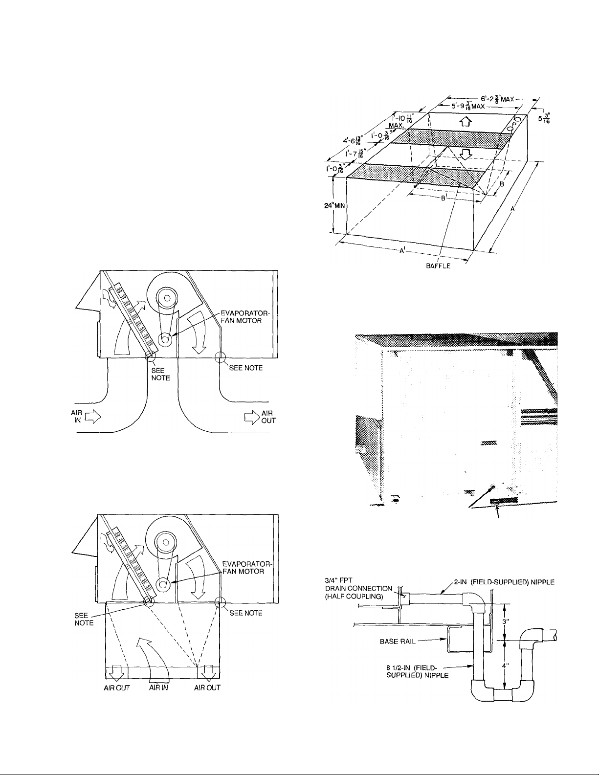
Step 4 — Make Unit Duct Connections - Unit
is shipped for through-the-bottom duct connections. Duct
work openings are shown in Fig. 5. Field-fabricated con
centric ductwork may be connected as shown in Fig. 6 and
7. Attach all ductwork to roof curb and roof curb basepans.
Refer to installation instructions shipped with accessory roof
curb for more information.
Step 5 — Trap Condensate Drain — See Fig. 4
and 8 for drain location. Plug is provided in drain hole and
must be removed when unit is operating. One V4-in. half
coupling is provided inside unit evaporator section for con
densate drain connection. An 8‘/2 in x %-in. diameter nip
ple and a 2-in. x %-in. diameter pipe nipple are coupled to
standard Y4-in. diameter elbows to provide a straight path
down through holes in unit base rails (see Fig. 9). A trap at
least 4-in. deep must be used.
i
Shaded area indicates block-off panels.
NOTE: Dimensions A, A' and B, B' are obtained from field-supplied
ceiling diffuser
Fig. 7 — Concentric Duct Details
NOTE. Do not drill in this area, as damage to basepan may resuit in
water leak.
Fig. 5 — Air Distribution — Through-the-Bottom
(50HJ024 Shown)
NOTE: Do not drill in this area, as damage to basepan may resuit in
water leak.
Fig. 6 - Concentric Duct Air Distribution
(50HJ024 Shown)
СОМЫЕстГоГ '-3/3" HOLES
Fig. 8 — Condensate Drain Details
Fig. 9 — Condensate Drain Piping Details
Loading...