


40GXC / 38GXC Cooling Only 40GXQ / 38GXQ Heat Pump
Inverter---Driven High Wall Duct---Free Split System Sizes 009 to 012
Service Manual
INTRODUCTION
This Service Manual provides the necessary information to service, repair, and maintain the 38/40GXC(Q).
TABLE OF CONTENTS
PAGE SAFETY CONSIDERATIONS . . . . . . . . . . . . . . . . . . . . . . . . . 1 MODEL / SERIAL NUMBER NOMENCLATURE . . . . . . . . . 2 STANDARD FEATURES AND ACCESSORIES . . . . . . . . . . . 3 SPECIFICATIONS . . . . . . . . . . . . . . . . . . . . . . . . . . . . . . . . . . . 4 DIMENSIONS . . . . . . . . . . . . . . . . . . . . . . . . . . . . . . . . . . . . . . 5 CLEARANCES . . . . . . . . . . . . . . . . . . . . . . . . . . . . . . . . . . . . . 6 SYSTEM OPERATING ENVELOPE . . . . . . . . . . . . . . . . . . . . 7 ELECTRICAL DATA . . . . . . . . . . . . . . . . . . . . . . . . . . . . . . . . 7 WIRING . . . . . . . . . . . . . . . . . . . . . . . . . . . . . . . . . . . . . . . . . . . 7 CONNECTION DIAGRAMS . . . . . . . . . . . . . . . . . . . . . . . . . . 7 WIRING DIAGRAMS . . . . . . . . . . . . . . . . . . . . . . . . . . . . . . 8-9 REFRIGERATION CYCLE DIAGRAM . . . . . . . . . . . . . . . . . 10 REFRIGERANT LINES . . . . . . . . . . . . . . . . . . . . . . . . . . . . . 11 SYSTEM EVACUATION AND CHARGING . . . . . . . . . . . . . 11 CONTROL SYSTEM . . . . . . . . . . . . . . . . . . . . . . . . . . . . 12-13 SEQUENCE OF OPERATION . . . . . . . . . . . . . . . . . . . . . . . . 13 MODES OF OPERATION . . . . . . . . . . . . . . . . . . . . . . . . . 13-15 TROUBLESHOOTING . . . . . . . . . . . . . . . . . . . . . . . . . . . . . . 16 DIAGNOSTIC CHARTS . . . . . . . . . . . . . . . . . . . . . . . . . . . . . 23 APPENDIX . . . . . . . . . . . . . . . . . . . . . . . . . . . . . . . . . . . . 24-27
SAFETY CONSIDERATIONS
Improper installation, adjustment, alteration, service, maintenance, or use can cause explosion, fire, electrical shock, or other conditions which may cause death, personal injury, or property damage. Consult a qualified installer, service agency, or your distributor or branch for information or assistance. The qualified installer or agency must use factory-authorized kits or accessories when modifying this product. Refer to the individual instructions packaged with the kits or accessories when installing.
Follow all safety codes. Wear safety glasses, protective clothing, and work gloves. Use quenching cloth for brazing operations. Have fire extinguisher available. Read these instructions thoroughly and follow all warnings or cautions included in literature and attached to the unit. Consult local building codes and National Electrical Code (NEC) for special requirements.
Recognize safety information. This is the safety-alert symbol !! When you see this symbol on the unit and in instructions or manuals, be alert to the potential for personal injury.
Understand these signal words: DANGER, WARNING, and CAUTION. These words are used with the safety-alert symbol. DANGER identifies the most serious hazards which will result in severe personal injury or death. WARNING signifies hazards which could result in personal injury or death. CAUTION is used to identify unsafe practices which may result in minor personal injury or product and property damage. NOTE is used to highlight suggestions which will result in enhanced installation, reliability, or operation.
!WARNING
ELECTRICAL SHOCK HAZARD
Failure to follow this warning could result in personal injury or death.
Before installing, modifying, or servicing system, main electrical disconnect switch must be in the OFF position. There may be more than 1 disconnect switch. Lock out and tag switch with a suitable warning label.
MODEL NUMBER NOMENCLATURE
INDOOR UNIT
40 |
|
|
GXQ |
009 |
|
--- |
1---01 |
|
|||||||||
|
|
|
|
|
|
|
|
|
|
|
|
|
|
|
|
||
Fan Coil Unit |
|
|
|
|
|
|
|
|
|
|
|
|
|
Voltage |
|||
|
|
|
|
|
|
|
|
|
|
|
|
|
1 --- 115---1---60 |
||||
|
|
Unit Type |
|
|
|
|
|
Nominal Capacity |
|
|
|||||||
|
|
|
|
|
|
|
|
|
|
|
|||||||
|
|
GXQ --- Heat Pump |
|
|
|
|
|
009 |
--- 3/4 Ton |
|
|
|
|
||||
|
|
GXC --- Cooling Only |
|
|
|
|
|
012 |
--- 1 Ton |
|
|
|
|
||||
38/40GXQ
OUTDOOR UNIT
38 |
|
|
|
GXQ |
009 |
--- |
1 01--- |
|
|
|
||||||||||
|
|
|
|
|
|
|
|
|
|
|
|
|
|
|
|
|
|
|
|
|
Air---Cooled Condenser |
|
|
|
|
|
|
|
|
|
|
|
|
|
|
Voltage |
|
|
|||
|
|
|
|
|
|
|
|
|
|
|
|
|
|
|
|
|
1--- |
115--- |
1--- |
60 |
|
|
Unit Type |
|
|
|
|
Nominal Capacity |
|||||||||||||
|
|
|
|
|
|
|
|
|
|
|
|
|||||||||
|
|
GXQ --- |
Heat Pump |
|
|
|
|
009 --- |
3/4 Ton |
|
|
|
|
|
|
|||||
|
|
GXC --- |
Cooling Only |
|
|
|
|
012 --- |
1 Ton |
|
|
|
|
|
|
|||||
|
|
|
|
|
|
|
|
|
|
|
|
|
|
|
|
|
|
|
|
|
|
|
|
|
|
|
|
|
|
|
|
|
|
|
|
|
|
|
|
|
|
SERIAL NUMBER NOMENCLATURE
|
01 |
|
06 |
|
V |
|
00001 |
|
||
Week of Manufacture |
|
|
|
|
|
|
|
|
Serial Number |
|
|
|
|
|
|
|
|
|
|
|
|
Year of Manufacture |
Manufacturing Site |
2

STANDARD FEATURES AND ACCESSORIES
Ease Of Installation |
|
Mounting Brackets |
S |
Low Voltage Controls |
S |
Comfort Features |
|
Microprocessor Controls |
S |
Wireless Remote Control |
S |
Rapid Cooling/Heating |
S |
Automatic Air Sweep |
S |
Cold Blow Prevention |
S |
Continuous Fan * |
S |
Auto Restart Feature |
S |
Memory Function |
S |
Auto Changeover |
S |
Energy Saving Features |
|
Inverter Driven Compressor |
S |
Sleep Mode |
S |
24 Hour Stop/Start Timer |
S |
Safety And Reliability |
|
Indoor Unit Freeze Protection |
S |
3 Minute Compressor Time Delay |
S |
High Compressor Discharge Temperature |
S |
Low Voltage Protection |
S |
Compressor Overload Protection |
S |
Compressor Over current Protection |
S |
IPM Module Protection |
S |
Ease Of Service And Maintenance |
|
Cleanable Filters |
S |
Diagnostic LED’s On Outdoor Board |
S |
Error Messages Displayed Front Panel |
S |
Application Flexibility |
|
Condensate Pump |
A |
Wind Baffle |
F |
Standard Warranty |
|
6 Year Compressor Limited Warranty* |
S |
2 Year Parts Limited Warranty* |
S |
Extended Warranty |
|
6 --- 10 Year Compressor Only |
O |
2 --- 6 Year Parts Only |
O |
2 --- 6 Year Parts; 1---6 Yr Labor |
O |
2 --- 6 Yr Parts; 6---10 Yr Compressor Only; 1---6 Yr Labor |
O |
Legend |
|
S Standard |
|
A Accessory |
|
O Optional |
|
F Field Fabricated |
|
INDOOR UNITS
A07892
Fig. 1 – Condensate Pump Accessory
On high wall fan coils, the condensate pump accessory is recommended when adequate drain line pitch cannot be provided, or when the condensate must move up to exit.
The pump has a lift capability of 12 ft (3.6 m) on the discharge side if the pump is mounted in the fan coil or 6 ft (1.8 m) on the suction side if the pump is remote mounted.
*For Residential applications. For Commercial applications, warranty is 1 year for parts and 5 years for compressor.
38/40GXQ
3
PRODUCT SPECIFICATIONS
|
|
|
System Model Number |
53GXC009--- --- ---1 |
53GXC012--- --- ---1 |
|
53GXQ009--- --- ---1 |
53GXQ012--- --- ---1 |
|
|
System |
System Voltage |
115 V |
115 V |
|
115 V |
115 V |
|
|
Control Voltage |
0 --- 24v DC |
0 --- 24v DC |
|
0 --- 24v DC |
0 --- 24v DC |
|
|
|
|
|
|||||
|
|
|
Capacity (Btuh) Clg/Htg |
8,600/--- |
12,000/--- |
|
8,600/10,800 |
12,000/11,200 |
|
|
|
SEER/HSPF |
16/--- |
16/--- |
|
16/7.7 |
16/7.7 |
|
|
Refrigerant |
Refrigerant Type |
|
|
R---410A |
|
|
|
|
|
|
|
|
|
|
|
|
|
Design Pressure (PSIG) |
560 |
560 |
|
560 |
560 |
|
|
|
|
|
|||||
|
|
|
|
|
|
|
|
|
|
|
|
Metering Device |
|
Capillary Tube at Outdoor |
|
||
|
|
|
|
|
|
|
|
|
|
|
|
Charge (lb) |
2.65 |
2.8 |
|
2.65 |
2.8 |
|
|
|
|
|
|
|
|
|
|
|
Compressor |
Type |
|
Twin Rotary Inverter Driven |
|
||
|
|
Locked Rotor Amp (LRA) |
33 |
33 |
|
33 |
33 |
|
|
|
|
Model |
C---6RZ092H1AB |
C---6RZ092H1AB |
|
C---6RZ092H1AB |
C---6RZ092H1AB |
|
|
|
Oil Charge (POE ---oz) |
11.6 |
11.6 |
|
11.6 |
11.6 |
|
|
|
Rated Current (RLA) |
4 |
3.92 |
|
4 |
3.92 |
|
|
|
|
|
|
|
|
|
|
|
Outdoor Motor |
Rpm/CFM |
830/1060 |
830/1060 |
|
830/1060 |
830/1060 |
|
|
|
|
|
|
|
|
|
|
|
Diameter (in) .. No. of Blades |
15.7 … 3 |
15.7 … 3 |
|
15.7 … 3 |
15.7 … 3 |
|
|
|
|
|
|||||
|
|
|
Motor (hp) |
0.04 |
0.04 |
|
0.04 |
0.04 |
|
|
|
|
|
|
|
|
|
38/40GXQ |
|
|
Capacitor |
2.5µF/450VAC |
2.5µF/450VAC |
|
2.5µF/450VAC |
2.5µF/450VAC |
|
Outdoor Coil |
Face Area (sq. ft) |
|
|
3.5 |
|
||
|
Motor Watts/HP |
|
20/0.027 |
|
||||
|
|
|
No. Rows |
|
|
2 |
|
|
|
|
|
Fins per inch |
|
|
18 |
|
|
|
|
|
Circuits |
|
|
2 |
|
|
|
|
Indoor Motor |
|
|
|
|
|
|
|
|
Rpm/Cfm (High) |
1200/290 |
1350/315 |
|
1200/290 |
1350/315 |
|
|
|
Rpm/Cfm (Medium) |
1060/245 |
1200/268 |
|
1060/245 |
1200/268 |
|
|
|
|
|
|||||
|
|
|
Rpm/Cfm (Low) |
700/224 |
1100/245 |
|
700/224 |
1100/245 |
|
|
|
|
|||||
|
|
|
|
|
|
|
|
|
|
|
|
Blower Diameter … Length (in) |
3.8 … 23 |
3.6 … 24.3 |
|
3.8 … 23 |
3.6 … 24.3 |
|
|
Indoor Coil |
Face Area (sq. ft) |
2.4 |
2.4 |
|
2.4 |
2.4 |
|
|
|
|
|
|
|
|
|
|
|
No. Rows |
|
|
2 |
|
||
|
|
|
|
|
|
|||
|
|
|
|
|
|
|
|
|
|
|
|
Fins per inch |
|
|
18 |
|
|
|
|
|
|
|
|
|
|
|
|
|
|
Circuits |
2 |
3 |
|
2 |
3 |
|
|
|
|
|
|
|
|
|
|
|
|
Connection Type |
|
|
Flare |
|
|
|
|
Refrigerant Lines |
Liquid (Mix Phase) (in) OD |
|
|
1/4” |
|
|
|
|
Vapor Line (in) OD |
|
|
1/2” |
|
||
|
|
|
|
|
|
|||
|
|
|
Condensate Drain (in) |
|
ID = 1/2” OD=5/8” |
|
||
|
|
|
Maximum Length (ft) |
65 |
65 |
|
65 |
100 |
|
|
|
Max Lift (Fan Coil Above) (ft) |
35 |
35 |
|
35 |
50 |
|
|
|
Max Drop (Fan Coil Below) (ft) |
35 |
35 |
|
35 |
50 |
4
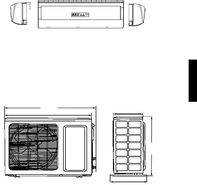
DIMENSIONS - INDOOR
H
|
|
|
|
|
|
|
|
|
|
|
|
|
|
|
|
|
|
|
|
D |
|
|
|
|
|
|
|
|
|
|
|
|
|
|
|
|
|
|
|
|
|
|
|
|
|
|
|
|
|
|
|
|
|
|
|
|
|
|
|
|
|
|
|
|
|
|
|
|
|
|
|
|
|
|
|
|
|
|
|
|
|
|
W |
|
|
|
|
|
|
|
|
|
A08289 |
||
|
|
|
|
|
|
|
|
|
|
|
|
|
|
|
|
|
|
|
|
|
|||
|
|
|
|
|
|
|
|
|
|
|
|
|
|
|
|
|
|
|
|
|
|||
|
|
|
|
|
|
|
|
|
|
|
|
|
|
|
|
|
|
|
|
|
|
|
|
|
|
|
|
|
|
|
|
|
|
|
|
|
|
|
|
|
|
|
|
|
|||
Unit Size |
|
|
|
W |
|
|
|
|
|
H |
|
|
|
D |
|
|
|
|
Net Operating Weight |
||||
|
|
In. (mm) |
|
|
|
|
In. (mm) |
|
|
In. (mm) |
|
|
|
|
Lbs. (Kg) |
||||||||
|
|
|
|
|
|
|
|
|
|
|
|
|
|||||||||||
9k |
|
30.3 (770) |
|
|
|
9.8 (250) |
|
|
7.84 (1.99) |
|
|
|
18.7 (8.5) |
||||||||||
12k |
|
32.7 (830) |
|
|
|
11.2 (285) |
|
|
8.9 (225) |
|
|
|
24.2 (11) |
||||||||||
Fig. 2 – Dimensions of Indoor Unit
DIMENSIONS - OUTDOOR
W
D
H
38/40GXQ
|
|
|
|
A08290 |
|
|
|
|
|
|
|
Unit Size |
W |
D |
H |
Net Operating Weight |
|
In. (mm) |
In. (mm) |
In. (mm) |
Lbs. (Kg) |
||
|
|||||
9k & 12k |
33.4 (848) |
12.6 (320) |
21.3 (540) |
88 (40) |
Fig. 3 – Dimensions of Outdoor Unit
5
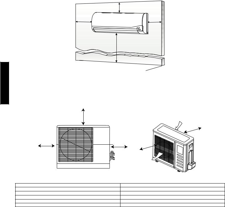
CLEARANCES - INDOOR
CEILING
6" (0.15m) min.
5" |
5" |
(0.13m) |
(0.13m) |
min. |
min. |
6' |
(1.8m) |
38/40GXQ
FLOOR
A07891
Fig. 4 – Indoor unit clearance
CLEARANCES - OUTDOOR
A
Air-inlet
E
D |
B |
C |
|
||
|
|
Air-outlet |
|
|
A07894 |
|
UNIT |
12k in. (mm) |
|
A |
20 (508) |
|
B |
20 (508) |
|
C |
24 (610) |
|
D |
12 (305) |
|
E |
12 (305) |
Fig. 5 – Outdoor Unit Clearance
6

38/40GXQ SYSTEM OPERATING ENVELOPE |
|
|
|
|
|
|
|
|
|
|
||||||||||||
|
|
|
|
|
|
|
Outdoor Temperature (_C) |
|
|
|
|
|
|
|
|
|
||||||
|
|
---40 ---35 ---30 ---25 ---20 ---15 ---10 ---5 |
0 |
5 |
10 |
15 |
20 |
25 |
30 |
35 |
40 |
45 |
50 |
55 |
60 |
|
|
|||||
|
|
120 |
|
|
|
|
|
|
|
|
|
|
|
|
|
|
|
|
|
60 |
|
|
|
|
110 |
|
|
|
|
|
|
|
|
|
|
|
|
|
|
|
|
|
55 |
|
|
|
|
|
|
|
|
|
|
|
|
|
|
|
|
|
|
|
|
|
50 |
|
|
|
|
|
|
|
|
|
|
|
|
|
|
|
|
|
|
|
|
|
|
|
|
|
|
|
TemperatureIndoor( F) |
100 |
|
|
|
|
|
|
|
|
|
|
|
|
|
|
|
|
|
45 |
TemperatureIndoor( C) |
|
|
|
|
|
|
|
|
|
|
|
|
|
|
|
|
|
|
95_F |
40 |
|
|||
|
90 |
|
|
|
|
|
|
|
|
|
|
|
|
|
|
|
|
|
|
|||
|
|
|
|
|
|
|
|
|
|
|
|
|
|
|
|
|
|
35 |
|
|||
|
|
|
|
|
|
|
|
|
|
|
|
|
|
|
|
|
|
|
|
|
||
|
|
|
|
|
|
|
|
|
|
|
|
|
Cooling |
|
|
|
|
|
|
|
||
|
|
|
|
|
|
|
|
|
|
|
|
|
|
|
|
|
|
|
|
|
||
|
|
80 |
80_F |
|
|
|
|
|
|
|
Continuous |
|
|
|
|
|
30 |
|
|
|||
|
|
|
|
|
|
Heating |
|
|
|
|
|
Operation |
|
|
|
|
|
25 |
|
|
||
|
|
70 |
|
|
|
Continuous |
|
|
|
|
|
|
|
|
|
|
|
|
|
|
||
|
|
|
|
|
|
|
|
|
|
|
|
|
|
|
|
|
20 |
|
|
|||
|
|
|
|
|
|
Operation |
|
|
|
|
|
|
|
|
|
|
|
|
|
|
||
|
|
60 |
|
|
|
|
|
|
|
|
|
|
|
|
|
|
|
60_F |
15 |
|
|
|
|
|
|
|
|
|
|
|
55_F |
|
|
55_F |
|
|
115_F |
|
|
10 |
|
|
|||
|
|
50 |
|
14_F |
|
|
|
|
75_F |
|
|
|
|
|
|
|
||||||
|
|
|
|
|
|
|
|
|
|
|
|
5 |
|
|
||||||||
|
|
|
|
|
|
|
|
|
|
|
|
|
|
|
|
|
|
|
|
|
|
|
|
|
40 |
|
|
|
|
|
|
|
|
|
|
|
|
|
|
|
|
|
0 |
|
|
|
|
---10 |
0 |
10 |
20 |
30 |
40 |
50 |
60 |
|
70 |
80 |
90 |
100 |
110 |
120 |
130 |
140 |
|
|
||
|
|
|
|
|
|
|
Outdoor Temperature (_F) |
|
|
|
|
|
|
|
|
|
||||||
|
NOTE: Low ambient controls cannot be used with these systems |
|
|
|
|
|
|
|
|
|
|
|
||||||||||
|
|
|
|
|
|
|
|
|
|
|
|
|
|
|
|
|
|
|
|
|
|
A09247 |
|
|
|
|
|
|
Fig. 6 – 38/40GXQ System Operating Envelope |
|
|
|
|
|
|
|
|||||||||
ELECTRICAL DATA |
|
|
|
|
|
|
|
|
|
|
|
|
|
|
|
|
|
|
||||
UNIT |
SYSTEM |
OPERATING |
|
COMPRESSOR |
OUTDOOR FAN |
|
|
INDOOR FAN{ |
|
|
|
MAX |
||||||||||
VOLTAGE |
VOLTAGE* |
|
|
|
|
|
|
|||||||||||||||
|
|
|
|
|
|
|
|
|
|
|
|
|
|
|
|
MCA |
FUSE/CB |
|||||
SIZE |
|
|
|
|
|
|
|
|
|
|
|
|
|
|
|
|
|
|
|
|
||
VOLTS---PH---HZ |
|
MAX/MIN |
|
RLA |
LRA |
FLA |
|
HP |
|
W |
VOLTS |
|
FLA |
HP |
W |
|
AMP |
|||||
|
|
|
|
|
|
|
||||||||||||||||
009 |
115---1---60 |
|
127/104 |
|
4.0 |
33 |
.6 |
|
.04 |
|
30 |
|
115 |
|
.3 |
|
.027 |
30 |
20 |
25 |
||
012 |
|
|
4.0 |
33 |
|
|
|
|
.45 |
|
.027 |
20 |
20 |
25 |
||||||||
|
|
|
|
|
|
|
|
|
|
|
|
|
|
|||||||||
* Permissible limits of the voltage range at which the unit will operate satisfactorily |
|
|
|
|
|
|
|
|
|
|
|
|||||||||||
{ Indoor fan powered from outdoor unit. |
|
|
|
|
|
|
|
|
|
|
|
|
|
|
|
|
|
|
||||
LEGEND |
|
|
|
|
|
|
|
|
|
|
|
|
|
|
|
|
|
|
|
|
|
|
FLA --- |
Full Load Amps |
|
|
|
|
|
|
|
|
|
|
|
|
|
|
|
|
|
|
|
|
|
LRA --- |
Locked Rotor Amps |
|
|
|
|
|
|
|
|
|
|
|
|
|
|
|
|
|
|
|
|
|
MCA --- |
Minimum Circuit Amps |
|
|
|
|
|
|
|
|
|
|
|
|
|
|
|
|
|
|
|
|
|
RLA --- Rated Load Amps |
|
|
|
|
|
|
|
|
|
|
|
|
|
|
|
|
|
|
|
|
||
WIRING
The main power is supplied to the outdoor unit. The field supplied connecting cable from the outdoor unit to indoor unit consists of four wires and provides the power for the indoor unit as well as the communication signal between the outdoor unit and indoor unit.
Voltage drop on the connecting cable should be kept to a minimum. Use cable size and max length below:
18 AWG |
50 ft. (16 m) |
16 AWG |
100 ft. (33 m) |
CONNECTION DIAGRAMS
CONNECTING CABLE
38/40GXQ
|
|
|
|
|
|
|
|
|
|
|
|
|
|
|
|
|
|
|
|
|
|
|
|
|
|
|
|
|
|
|
|
|
|
|
|
|
|
|
|
|
|
|
|
|
|
|
|
|
|
|
|
|
|
|
|
|
|
|
|
|
|
|
|
|
|
L |
N |
L |
|
N |
GND |
|
S |
|
|
|
|
|
L |
|
N |
GND |
S |
||||
Main Power |
Power to |
|
|
|
|
|
|
|
|
|
|
|
Power to |
|
|
|
|
||||
Supply |
Indoor |
Ground |
Control |
|
|
|
|
|
|
Indoor |
Ground |
Control |
|||||||||
|
|
|
|
|
|
Unit |
|||||||||||||||
|
|
|
Unit |
|
|
|
|
|
|
|
|
|
|
|
|
|
|
|
|||
115-1-60 |
115-1-60 |
|
|
|
|
|
|
|
|
|
|
|
115-1-60 |
|
|
|
|
||||
|
|
|
|
|
|
|
|
|
|
|
|
|
|
|
|
|
|
|
|
|
|
9 &12K Outdoor Unit
Use a four (4) Wire Cable (Do Not use thermostat wire)
9 &12K Indoor Unit
A08292
Fig. 7 – Connection Diagrams
7

8
38/40GXC(Q)
WIRING DIAGRAMS
|
|
COMP. |
|
|
R |
COMP |
E YE/GN |
|
|
CURRENT |
|
|
|||
OD COIL |
OD AIR |
DISCHARGE |
|
|
|
C |
|
TEMP. |
SENSOR |
|
|
S |
|||
TEMP. |
TEMP. |
|
|
|
|
|
|
SENSOR |
SENSOR |
SENSOR |
|
WHT |
GRN |
RED |
|
|
|
|
|
|
|
|
|
|
|
|
|
YE/GN |
|
|
|
|
|
|
|
|
RED |
|
|
WHT |
GRN |
RED |
|
|
|
|
|
|
|
|
|
|
|
|
|
|
|
|
|
|
|
|
|
|
||
|
|
|
|
|
|
|
|
|
|
|
|
CN3 |
|
CN2 |
|
CN1 |
|
CN4 |
|
|
U(X11) |
V(X12) |
W(13) |
ID COIL |
RETURN |
DISPLAY BOARD |
|
|
|
|
|
|
|
|
|
|
|
CN7 |
|
CN6 |
|
|
|||||
|
|
|
|
|
|
|
|
E (X4) |
|
|
|
|
|
|
CN8 |
|
|
||||||
TEMP. |
AIR TEMP. |
|
|
|
|
|
|
|
|
|
|
|
|
|
|
|
|
|
|
|
|
|
|
SENSOR |
SENSOR |
|
|
|
|
|
|
|
|
|
|
|
|
|
|
|
|
|
|
|
|
|
|
|
|
|
|
|
FIELD |
|
|
BRN |
FILTER |
WHT |
X5 |
BRN |
|
|
|
|
|
|
|
|
|
||
|
|
|
|
|
|
|
|
|
|
|
MAIN |
|
|
|
|
|
|||||||
|
|
|
|
|
POWER |
L |
L |
|
1 |
3 |
|
X3 (L) |
|
RELAY |
|
|
|
|
|
|
|
||
|
|
|
|
|
SUPPLY{N |
N |
BLU |
2 E4 |
WHT |
X2 (N) |
|
|
|
|
|
|
|
|
|
|
|||
X9 MK1 |
X13 |
X9 |
X12 |
|
XT |
|
L |
BRN |
|
YE/GN |
|
|
COM |
NO |
|
|
|
|
|
|
|
|
|
|
|
|
|
|
|
|
|
|
|
|
|
|
|
|
|
|
|||||||
|
|
|
|
BLK |
|
BLU |
|
|
|
|
|
|
|
|
|
|
|
|
|
|
|
||
|
|
|
DATA1 |
S |
|
N |
|
|
|
|
|
|
|
|
|
|
|
|
|
|
|
|
|
|
|
|
YE/GN |
|
|
|
|
|
|
|
|
|
|
|
|
|
|
BLU |
|
|
|||
|
|
|
|
|
|
YE/GN |
|
|
|
|
|
|
|
|
|
|
|
|
|
|
|
||
|
AP2 |
|
|
BLU |
|
|
|
|
|
|
|
|
|
|
|
|
|
|
|
|
|
||
|
|
|
|
|
|
|
|
|
|
|
|
|
|
|
|
|
|
|
|
|
|||
|
|
N |
N |
|
|
|
BLK |
|
|
|
X21 |
X14 |
X7 |
X16 |
X10 |
|
|
X6 |
X9 |
|
|
||
|
|
BRN |
|
|
|
|
|
|
|
|
|
|
|||||||||||
|
|
|
|
|
S |
|
|
|
|
X1 (COM) |
|
|
|
|
|
X15 |
|
|
BRN |
|
X17 |
||
|
|
|
ACL1 |
|
L |
|
|
|
|
|
|
|
|
|
|
|
|
|
|
||||
|
|
|
|
|
|
|
XT2 |
|
|
|
|
|
|
|
|
|
|
|
|
|
|
|
|
X3 |
X1 |
X2 |
FAN1 |
|
|
|
|
|
|
|
|
|
RED |
|
|
|
BLU |
GRN |
BRN |
AC |
|
|
|
|
|
|
|
|
|
|
|
|
|
|
|
|
|
BLU |
|
|
|
|
FILTER |
AC |
|
||
|
|
|
|
|
|
|
|
|
|
|
|
|
BLK |
BRN |
|
|
|
|
|
|
|||
|
CAP |
1 |
2 |
BRN |
BLU |
|
2 |
1 |
CAP |
|
|
I.D. FAN |
O.D. FAN E |
|
|
||
|
|
|
|
||
MOTOR |
MOTOR |
|
|
|
|
TRANSFORMER |
YE/GN |
|
|
|
|
|
WHT |
|
|
|
|
|
|
|
|
|
LOUVER MOTOR
38GXC009/012---1 |
40GXC009/012---1 |
COOLING ONLY INDOOR UNIT |
COOLING ONLY INDOOR UNIT |
115-1-60 |
115-1-60 |
|
A09344 |
|
Fig. 8 – 38-40GXC009/012 Cooling Only Wiring Diagram |
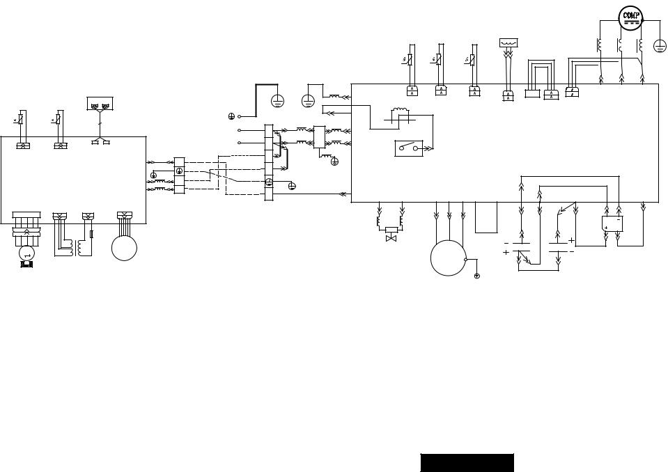
WIRING DIAGRAMS (CONT.)
9
ID COIL |
RETURN DISPLAY BOARD |
TEMP. |
AIR TEMP. |
SENSOR |
SENSOR |
X9 MK1 |
X13 |
X9 |
X12 |
|
XT |
|
|
BLK |
|||
|
|
|
|
||
|
|
|
DATA1 |
S |
|
|
|
|
YE/GN |
||
|
AP2 |
|
N |
N |
|
|
|
BRN |
|||
|
|
|
|
BLU |
|
|
|
|
ACL1 |
|
L |
X3 |
X1 |
X2 |
FAN1 |
|
|
TC
I.D. FAN
MOTOR
TRANSFORMER
LOUVER MOTOR
38GXQ009/012---1
HEATPUMP INDOOR UNIT 115-1-60
|
OD AIR |
COMP. |
|
R |
|
E |
|
OD COIL |
DISCHARGE |
CURRENT |
|
S |
C |
YE/GN |
|
TEMP. |
TEMP. |
TEMP. |
SENSOR |
|
|
||
|
|
|
|||||
SENSOR |
SENSOR |
SENSOR |
WHT |
GRN |
|
RED |
|
|
|
|
|
|
|
|
|
|
|
|
|
|
|
|
|
|
|
|
|
|
WHT |
GRN |
RED |
|
|
|
|
|
|
|
|
|
|
|
|
|
RED |
|
|
|
|
|||
|
|
|
|
|
|
|
|
|
|
|
|
|
|
|
|
|
|||
|
|
|
YE/GN |
|
|
|
|
|
|
|
|
|
|
|
|
|
|||
|
|
|
|
|
|
|
|
|
|
|
|
|
|
|
|
|
|
||
|
|
|
|
|
|
X4 (E) |
|
|
|
|
|
|
|
|
|
U(X11) |
V(X12) |
W(X13) |
|
|
|
|
|
|
|
|
CN3 |
CN2 |
|
CN1 |
|
CN4 |
CN7 |
CN8 |
CN6 |
|
|
|
|
|
|
|
|
|
|
|
|
|
|
|
|
|
|||||||
|
|
|
|
|
|
X5 |
|
|
|
|
|
|
|
|
|
|
|
||
FIELD |
|
|
|
|
|
|
|
|
|
|
|
|
|
|
|
|
|
|
|
|
BRN |
FILTER |
RED |
|
|
|
|
|
|
|
|
|
|
|
|
|
|
||
POWER |
|
1 |
|
|
|
|
|
|
|
|
|
|
|
|
|
|
|
||
SUPPLY{L |
L |
BLU |
E |
3 |
WHT |
X3 (L) |
|
|
BRN |
|
MAIN |
|
|
|
|
|
|
|
|
N |
N |
|
2 |
4 |
|
X2 (N) |
|
|
|
|
|
|
|
|
|
|
|
||
|
L BRN |
|
|
YE/GN |
RELAY |
|
|
|
|
|
|
|
|
|
|
|
|
|
|
|
|
|
|
|
|
|
|
|
|
|
|
|
|
|
|
|
|||
|
BLU |
|
|
|
|
COM |
NO |
|
|
|
|
|
|
|
|
|
|
|
|
|
N |
|
|
|
|
|
|
|
|
|
|
|
|
|
|
|
|
|
|
|
YE/GN |
|
|
|
|
|
|
|
|
|
|
|
|
|
BLU |
|
|
|
|
|
S |
10BK |
|
|
X1 (COM) X8 |
X18 |
|
X21 X14 |
X7 |
X16 |
X10 |
X15 |
|
X6 |
BRN |
|
|
X17 |
|
|
|
|
|
|
|
|
X9 |
|
|
||||||||||
|
XT2 |
|
|
|
|
|
|
|
|
|
|
|
|
|
|
|
|
|
|
|
|
|
|
|
|
|
|
|
BLK RED BRN |
|
|
BLU |
GRN |
BRN |
AC |
|
|
||
|
|
|
|
|
|
|
|
|
|
BLU |
|
|
|
FILTER |
AC |
|
|
||
4 WAY VALVE |
CAP |
1 |
2 |
BRN |
BLU |
O.D. FAN |
2 |
1 |
CAP |
|
|
E |
|
|
|
|
|
MOTOR |
YE/GN |
|
|
|
|
|
WHT |
|
|
|
|
|
|
|
|
|
40GXQ009/012---1
HEATPUMP OUTDOOR UNIT 115-1-60
A09345
Fig. 9 – 38-40GXQ009/012 Heat Pump Wiring Diagram
38/40GXC(Q)
 Loading...