

Page 1
Number One
Air Conditioning
Mater
e
Division of Carrier Corporation
Carrier Parkway ♦ Syracuse NY 13201
Air-Cooled Condensing Units
TRANSPORTATION DAMAGE
File claim with shipping company if shipment is
damaged or incomplete.
PRELIMINARY SURVEY
Consult local building codes and National Electrical
Code (NEC) for special installation requirements.
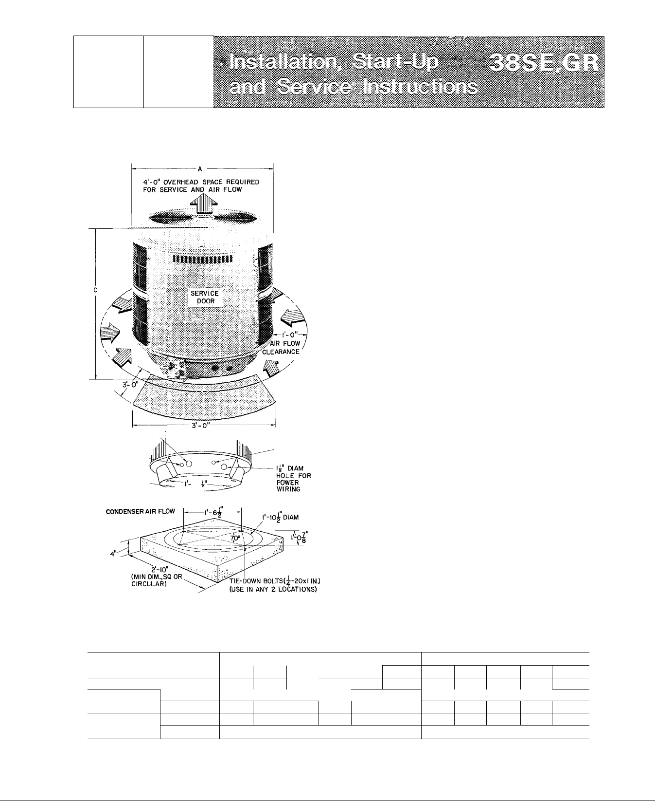
When installing unit, allow sufficient space for airflow
clearance, wiring, refrigerant piping and servicing unit.
Recommended minimum requirement is 3 ft (Fig. 1).
Position unit so water from roof or eaves will not pour
directly on top of unit.
Install unit on a solid, level mounting pad. Position
tie-down bolts in pad. Any 2 holes in unit base may be used
to fasten unit to pad.
38GR Condensing Units Connected to Carrier-Approved
Evaporators with Carrier Accessory Tubing — 38GR units
contain correct refrigerant charge when evaporator is same
size, or one size larger than condensing unit and are
connected with Carrier accessory tubing. Check refrigerant
38SE,GR
SUCTION LINE CONN (ON SERVICE VALVE)
LIQUID LINE
CONN.(ON SERVICE,!
VALVE)
5." |3'*
16 “ ' 8
MTG SLOTS
(USE ANY 2)
uSl SPACE REQUIRED FOR SERVICE
--------------
10^
CONCRETE MOUNTING PAD^(SQUARE OR CIRCULAR)
^CONCRETE PAD SHOULD WEIGH |-| TO 2 TIMES WEIGHT OF UNIT
DIAM HOLE
FOR CONTROL
WIRIN(3
Fig. 1 — Dimensions, Connections and Mounting Pad
Table 1 — Installation Data
CONDENSING UNIT
OPERATING WT (lb)
DIMENSIONS
(ft-in.)
REFRIG
CONN.
*38GR005,006 and 38SE004,045,055 supplied with 3/4-in to 1 1 /8-in suction valve connection adapter (field installed) for 1 1 /8-in suction
line (field supplied)
Diam A
Height В
Suet ODF
Liq ODF
002
151 170 182 194 1 234
2-4
003
2-4 2-4 2-4
%
y.
38GR
004
2-5У4
L
V
4
charge when tubing lengths are above 50 feet. See Refrig
erant Charging for details.
38SE Condensing Units Connected to Carrier-Approved
Evaporators — 38SE units contain correct system refrig
erant charge when evaporator is same size as condensing
unit, and they are connected with 25 ft or less of
field-supplied tubing of recommended size (see Piping
Connections) or 50 ft or less of Carrier accessory tubing.
Check refrigerant charge for maximum system efficiency.
See Refrigerant Charging for details.
38GR,SE Condensing Units Connected to Non-Carrier
Evaporators — Check refrigerant charge when the 38GR,SE
is added to a system in which other than a Carrier approved
evaporator is being used or where the evaporator has been
previously installed. Field-supplied refrigerant piping must
be in accordance with Refrigerant Piping Data table.
Use an evaporator coil with a bleed-type expansion
device. If coil does not have a bleed-type expansion device
it may be necessary to add an accessory start capacitor and
relay to condensing unit. This would require removing
compressor start thermistor (PTC device) on units so
equipped.
PIPING CONNECTIONS
The 38GR,SE condensing units can be connected to
evaporator sections using Carrier accessory tubing package
or field-supplied tubing of refrigerant grade (Accessory
045
V
'A ’/4*
005
2-8 2-8
006
260
3/*
002
176 180
2-4
003 004
2-4 2-8 3-8 3-8
V
4
У4 У4 *
38SE
192
2-5У4
Ys
045 055
248
255
3/*-
4
%*
© Carrier Corporation 1975
Fornn 38SE-3SI
Page 2
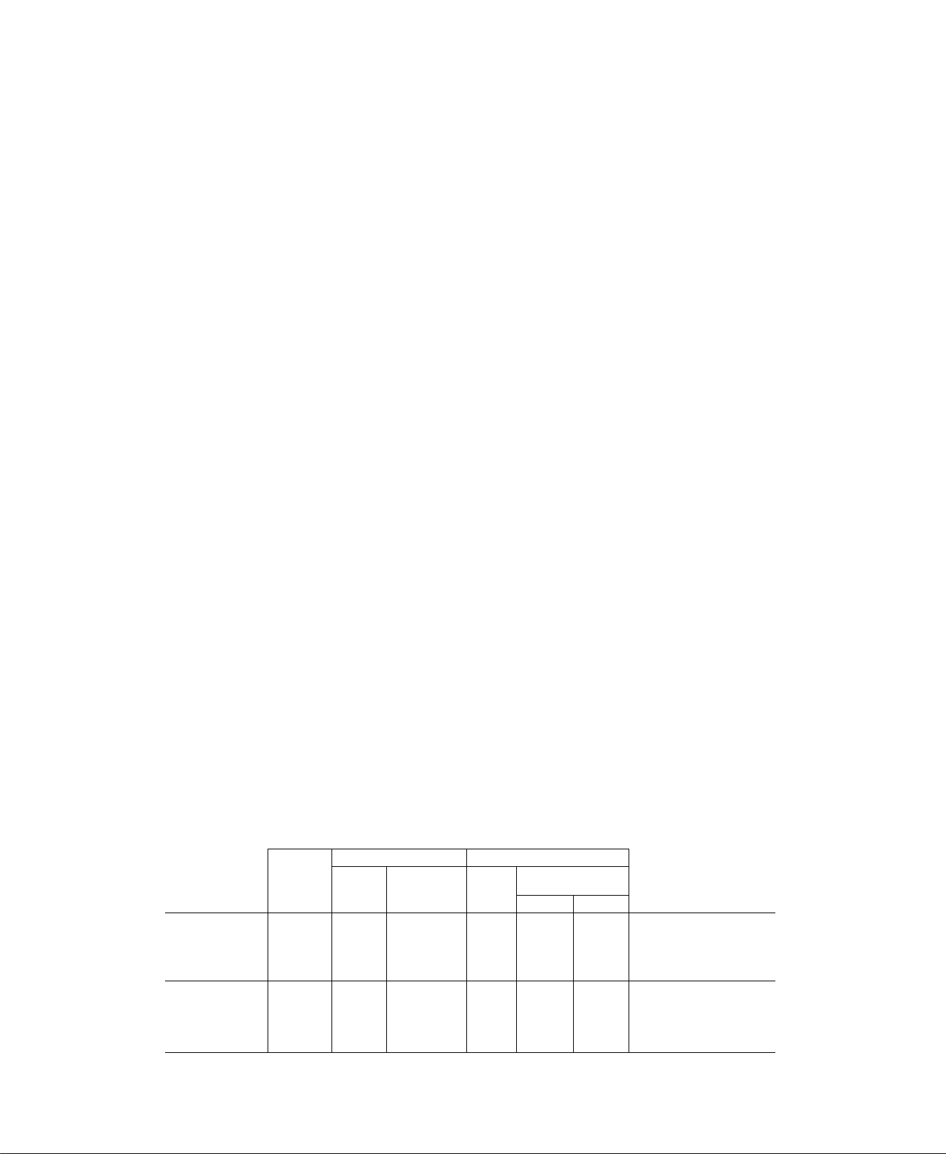
tubing not available for 38GR006.) See Table 2 for
accessory tubing sizes and Table 3 for recommended
field-supplied tubing sizes. (Where evaporator is 20 ft or
more below condensing unit, reduce liquid line size one
diameter — min 1/4-in. OD.)
A capacity reduction results if accessory tubing is used
in 38SE004,045,055 systems. For example, when a 25 ft
accessory tubing package is used, there is a capacity
reduction of 2 1/2% on 38SE004, 3 3/4% on 38SE045 and
5% on 38SE055 systems. For maximum capacity from
these systems, use tubing sizes shown in Table 3.
Connection Recommendations — Do not use damaged or
contaminated tubing. Do not use less than 10 ft of liquid
line. Do not cut 5/16-in or 1/4-in. liquid line. Bend or coil
to fit.
If accessory tubing package or evaporator section has
been open for more than 15 seconds per connection,
evacuate or purge evaporator coil and tubing system (use
field-supplied refrigerant, not unit refrigerant) Always
evacuate or purge if field-supplied tubing is used.
When making piping connections, be sure to provide
clearance at unit for electrical connections.
Connect refrigerant liquid and suction lines to condensing
unit (Fig 1). Unit compatible fittings permit mechanical
(quick-connect) or sweat connections.
Table 2 — Accessories
PART NO.
HH01AD040
HH93AZ040
HH51AR001
HH07AT070,
HH07AT074
HH93AZ076
HH01AD042
HH93AZ042
HH01YA092
HH93YZ094
32LT900301
Low-Voltage Control — Honeywell Deluxe Thermostat
Thermostat Subbase
Comfort Control Center (Use with HH01AD040.)
Low-Voltage Control — Honeywell Thermostat
Thermostat Subbase (with Automatic Changeover)
Low-Voltage Control — Honeywell Thermostat
Thermostat Subbase
Low-Voltage Control — Grayson Thermostat
Thermostat Subbase
Solid State Head Pressure Control,
and/or motor required.
38GR005,006; 38SE004.045.055 Units - When using
1 1/8-in. field-supplied siictlSff'line, remove suction line
adapter taped to compressor suction line. Connect 3/4-in.
end of adapter to unit suction line compatible fitting.
Sweat connect refrigerant suction line to 1 1/8-in. end of
adapter. Connect liquid refrigerant line to unit. When a
7/8-in. field-supplied suction line is used on 38SE003 or
38GR045, a field-supplied 3/4-in. to 7/8-in. suction line
adapter must be provided.
MECHANICAL CONNECTION (Mate one set of connec
tions at a time.)
1. Loosen nut on compatible fitting one turn. Do not
remove.
2. Remove plug and be sure 0-ring is in the groove inside
the compatible fitting.
3. Cut tubing to correct length.
4. Use gage on tag attached to service valve to mark tube
end for correct insertion depth. Insert tube into com
patible fitting until it bottoms. (Tube should be inserted
at least as far as mark on tubing.)
5. Tighten nut until it bottoms on back coupling flange
SWEAT CONNECTION (Use refrigerant grade tubing.)
1. Remove locking nut, rubber 0-ring and Schrader core
from valve.
2. Cut tubing to correct length.
DESCRIPTION
Special field-installed fan
38GC900-152
38GB900021
38GC900031
38GC900041 18
38GS900221 25
38GC900061 35
38GC900191
38GC900071 10
38GC900081
38GC900091
38GC900101
38GC900in
Indoor Fan Relay (Six — 38BA400693)
Thermal Expansion Valve (Six — EA61DC100)
Len gth
(ft)
UNIT
Motor No.
Fan No.
UNIT
Motor No.
OD
(in.)
10
50
18
25
35
50 Ve
TUBING PACKAGES
L iquid Suction*
Tube End
OD
(in.)
%
Ve
Ve
Vie
%
V
/8
V
/8
Ve
Ve
Ve Ve Vet
Ve
Ve Ve
Ve
Ve
Ve
Ve
%
/8
V
'8
38SE002,003
HC38VE851
LA01AA020
38GR002,003,004,045
HC38VE851
OD
(in.)
/4
Ve
Ve
Ve
%
V
Ve
Ve
Ve
Evap
Vet
Vet Ve
Vet
Vet
Ve
Ve
Ve
Ve
Ve
Tube End
OD (in.)
Cond
Ve
Ve
Ve
Ve
Ve
V
/4
V
/4
Ve
HC40VL701
LA01AA023
38GR005,006
HC40VL701
38SE002, 38GR002
38SE003,004,045,055
38GR003,004,045,005
Ve :
*Suction line is insulated and has a 90 bend at one end
fFor 5/8-in evaporator connection, cut off 3/4-in. end.
NOTE: Do not cut 3/8-in OD liquid line to a length shorter than 10 feet Do not cut 5/1 6-or 1/4-in liquid line.
38SE004
UNIT
Page 3
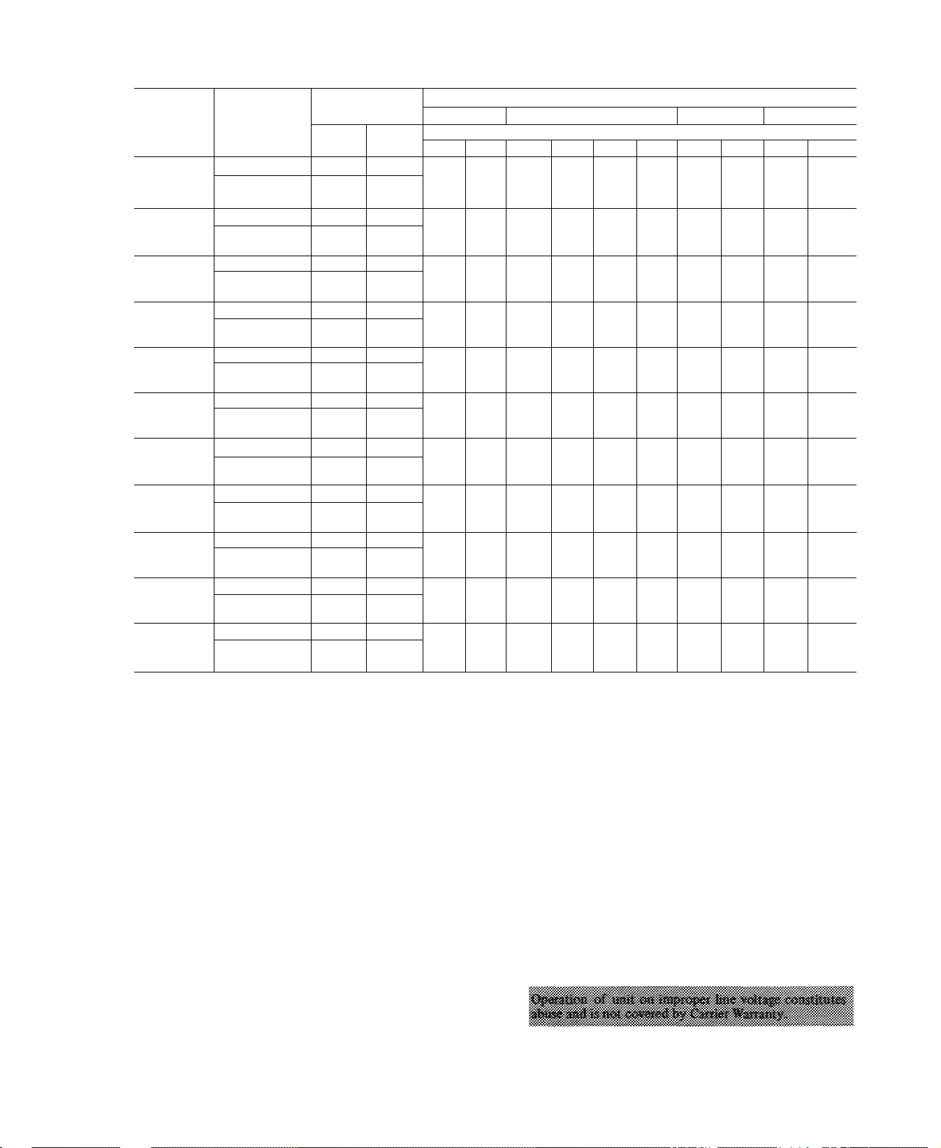
Table 3 — Field-Supplied Piping Data
COND
UNIT
38GR002
38GR003
38GR004
38GR045
38GR005
38GR006
38SE002
38SE003
38SE004
38SE045
38SE055
REFRIG
CONTROL
TXV 90 90
Cap. Tube or
AccuRater'*'^
TXV
Cap. Tube or
AccuRater
TXV
Cap. Tube or
AccuRater
TXV
Cap. Tube or
AccuRater
TXV 90
Cap. Tube or
AccuRater
TXV 90 90
Cap. Tube or
AccuRater
TXV
Cap. Tube or
AccuRater
TXV
Cap. Tube or
AccuRater
TXV
Cap. Tube or
AccuRater
TXV 90
Cap. Tube or
AccuRater
TXV
Cap. Tube or
AccuRater
Cap. Tube — Capillary Tube
TXV — Thermal Expansion Valve
MAX COND
UNIT HT (ft)
Above
Evap
150
90
150 50
90 90
150
90
ISO 50
150 50
150 50
90 90
150
90
150 50
90 90
150 50
150
90 90
150 50
NOTES:
1 Systems with over 50 ft separation between condensing unit and evaporator require refrigerant
2 Reduce liquid line diameter by 1/8-in OD (minimum 1/4-in OD) when evaporator is 20 ft or
REFRIGERANT LINE LENGTH (ft)
25-50
Below
Evap
50
90
50
90
90
50
90
90
50
charge adjustment to ensure the proper superheat at compressor See Refrigerant Charging, page
5 Oil charge adjustment may also be required
Suet
%
^4 %
%
IVs
iVs
V
u
Vs
IVa
IVs
iVa
Liq
% V4
%
%
%
%
V
'8
V
'8
%
\
%
Suet
51-75 76-100
Line Diameter (in. OD)
Suet Liq
Liq
Vs V4
V4 Vs V4
V4 Vs Vs
Vs
V
IVs
V
IVs
Vs
V
Vs Vs
/A
V
Vs
'8
IVs
%
IVs
V
IVs
V
Vs V.
IVs
IVs Vs
Vs
IVs
IVs
IVs
Vs
Vs V4
Vs Vs V2
V
Vs
Vs
Vs
V2
V.
101-125
Suet Liq
V4
Vs
IVs
IVs
V
/8 Vs
Vs
IVs
IVs
IVs
Vs
Vs
V
V
Vs
Vs
Vs
V
Va
126-150
Suet
V4 Vs
V, Vs
Vs
Vs
IVs
IVs
Vs Vs
Vs
IVs
IVs
IVs
Liq
Va
Va
Vs
Vs
V
'8
Vs
Va
Vs
more below condensing unit
3. Insert tube into compatible fitting. Wrap top and
bottom of service valves in wet cloth to prevent damage
by heat. Solder with low-temperature (450 F) silver
alloy solder.
4. Replace Schrader core.
5. Evacuate or purge system with field-supplied refrigerant.
SERVICE DOOR
Service door can be opened or removed for wiring or
servicing unit
Remove 3 screws from left side of service door (Fig. 1)
to swing door open.
Door Removal — Turn power off. Disconnect wiring from
control panel mounted on door. Refer to Fig. 7 and 8.
After wiring is disconnected, lift door from roll pin hinges.
ELECTRICAL DATA AND WIRING
Field wiring must comply with local and national fire,
safety and electrical codes. Voltage to unit must be within
± 10% of voltage indicated on nameplate. On 3-phase units,
phases must be balanced within 2%. Contact local power
company for correction of improper line voltage.
See Table 4 for recommended wire and fuse sizes. When
making electric connections, provide clearance at unit for
refrigerant piping connections.
Page 4
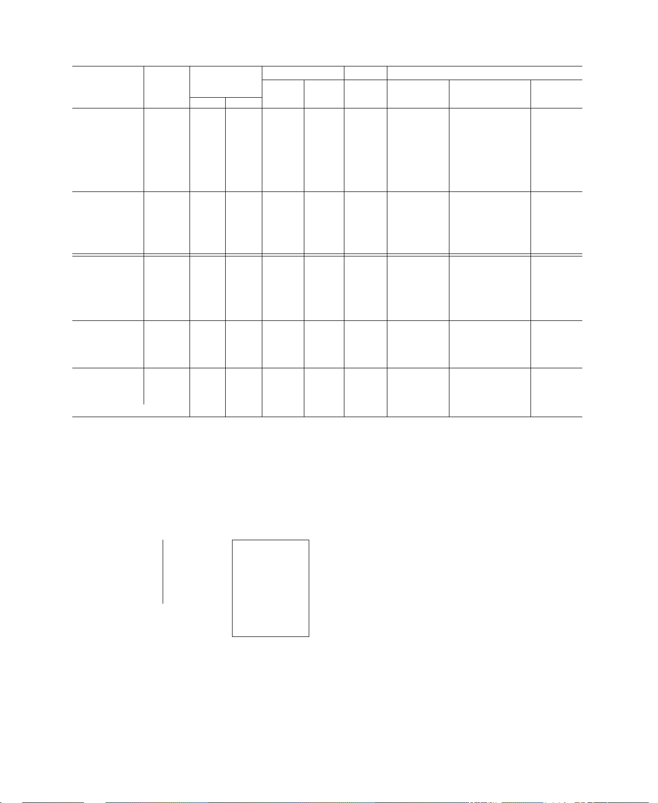
Table 4 — Electrical Data
COND
UNIT
V/PH
OPER
VOLTS*
COMPR
LRA FLA
Max Min
38GR002---
38GR0023I0
38GR003---
38GR003310
38GR004---
230/1 253 207
38GR0043J0
38GR045---
38GR005---
38GR006---
38GR003---
38GR0034Í0
38GR004---
38GR0044J0 200/3
38GR045---
220 180
72.0
72.0
90.0
90.0
100.0
100 0
94.0
106.0
135.0
60.0
70.0
69.0
80 0
79.0
38GR005--- 87.0
38GR006---
38GR003---
38GR0035Í0
113.0 24.0
50.0
60.0
38GR004--- 60.0
38GR0045J0 230/3
38GR045--38GR005---
38GR006--38GR004---
38GR004610
38GR045---
460/3
38GR005--38GR006---
38SE002--.
38SE003--38SE004---
230/1
38SE045---
38SE055---
L
__
253
506
253
207 70.0
414
207
67.0
70.0
98.0
30.0
35.0
35 0
35.0
49.0
65.0
72.0
90.0
94.0
106.0
Corresponding wire sizes and wire lengths
FLA — Full Load Amps
LRA — Locked Rotor Amps
--------Electrical data shown applicable to all units for which com
plete model numbers are not shown Example: 38GR003--applies to all 003 models except 38GR003Ji0.
FAN BRANCH CIRCUIT
Wire
FLA
Sizet
(AWG)
14.8
14.8 1 0 12
19.2
19.2
22.9 1 3
22 9
23.9 1.3
27.9 2.0 8 42 0 Í
39.0 2.0 6
13.0
13.0
14 0
14 0
16.7 1.3 12
18.3 2.0
11.5
11.5
12.6
12.6
14 3
16.4
19.9
6.5
6.5
7.2
8 8
10 4
10.3
14.8
19 2
23 9
28.0
1.0 12 32.0 30
1.1 10 39 0 40
1.1
1 3
1.1
1 1 12
1.3 12
1.3
2 0
1 1
1 1 12
1.3
1 3 12
1 3
2 0 10
2 0 10 47 0
5
5
.5
1.3
1.3
.8
.8
.8
1 3
2.2
1. ' 32 0 30
10
10
10
8 49.0
12 42.0
Ì
12 1.'^ zL.
Í
10
r
8
12 25
mf.
12
12 42 0
14
\-xi:
14
14
i n ;
14
1 n
14
14
12 10
10
10 »
10
39.0 L 40
33.0
33-0
47.0
42.0
39.0
39.0 i: ' 30
33 0 i
46.0 40
64.0 / 50
52.0 1
47.0
47.0
56.0 35
110.0
110.0
100.0 1
81.0 Í
70.{'
29 1 '■
40.0
*Permissible limits of the voltage range at which the unit will oper
ate satisfactorily
tCopper wire sizes and lengths Use latest National Electrical Code
(NEC) for aluminum wire sizing
-> Maximum dual element fuse size
NOTE Control circuit voltage is 24 volts on all units On 3-phase
units, phases must be balanced within 2%
Max
Ftt
Wire
32 0 $XÙ
32 0 SBJB
430
Fuse
Ampst
50
50
50
60
80
30
30
30
35
25
25
25
30
45
15
15
15
20
20
20
30
40
50
60
3-PHASE
CONN.TO
FUSED
DISCONNECT
I-PHASE
CONN TO
FUSED
DISCONNECT
— GROUND LEAD-
L
—
-
-----------------
■
---------------
--------
COND UNIT
GROUNDING LUG
BRN _
ORN
-----------
BLK
-----------
(38GR ONLY)
A—A Splice Connections
---------
Field Wiring
---------
Factory Wiring
Fig. 2 — Line Power Connections
Install a Branch Circuit Fused Disconnect of adequate size
to handle unit starting current Locate disconnect within
sight of and readily accessible to the unit, per section
440-14 of National Electrical Code (NEC).
1076
Bring Line Power Leads Into Unit — Extend leads from
fused disconnect thru hole provided in base pan (Fig. 1)
and into unit junction box.
CONNECT GROUND LEAD TO GROUND LUG OR
SCREW IN JUNCTION BOX for safety. Connect power
wiring. See Fig. 2. Splice line power leads to brown and
orange pigtails on 1-phase units or brown, orange and black
pigtails on 3-phase units. Use wire nuts supplied with unit.
Tape each connection. When aluminum field wire is used,
lubricate splices with splice compound (also supplied)
before using wire nuts.
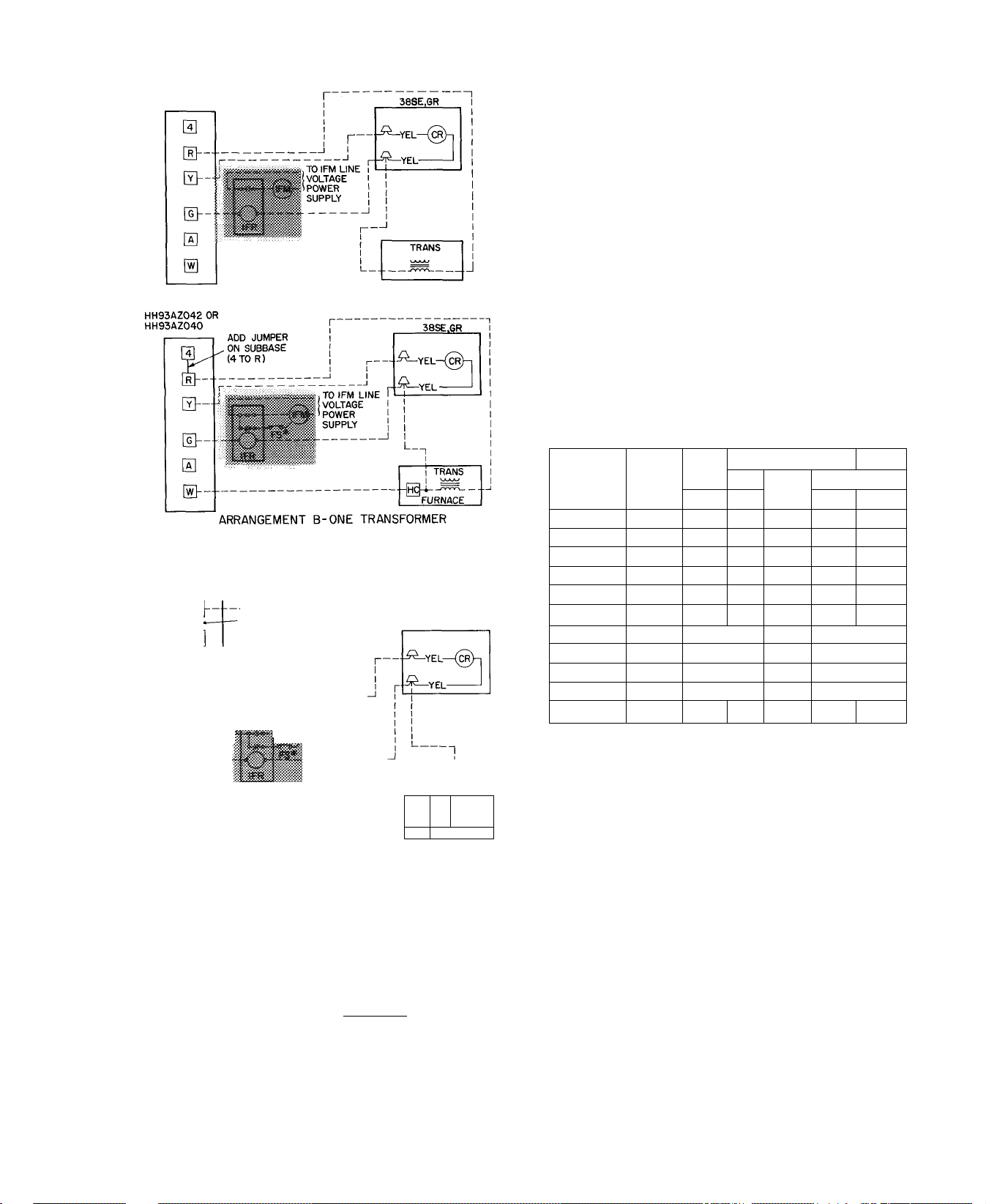
Control Power (24 v) wiring is brought thru hole provided
in unit base pan (Fig. 1) and into low-voltage section of
unit junction box. Splice control leads to yellow pigtails on
control relay. See Fig. 3. For aluminum wire splices use
factory supplied and lubricated wire nuts. Furnace or fan
coil transformer must be used as 24-v supply for system as
shown in Fig. 3. All 38SE units are equipped with
transformer used to power contactor thru unit control
circuit only, and must not be used to power thermostat
circuit.
Page 5
r
THERMOSTAT SUBBASE
HH93AZ042 OR
HH93AZ040
THERMOSTAT SUBBASE
* CONNECT FS TO LOW-SPEED INDOOR FAN TERMINAL
WHEN TWO-SPEED FAN IS USED
THERMOSTAT SUBBASE
HH93AZ076
N
ARRANGEMENT A-(COOLING ONLY)
(COOLING AND ONE-STAGE HEATING)
-LEAVE JUMPER ON
SUBBASE (RH TORO)
38SE.gr
0
&■
0
TOIFM LINE
..0^ VOLTAGE
POWER
m SUPPLY
&-
@--
1TRANS
HCl
[vië
ARRANGEMENT C-ONE TRANSFORMER
(COOLING AND TWO-STAGE HEATING)
* CONNECT FS TO LOW-SPEED INDOOR FAN TERMINAL
WHEN TWO-SPEED FAN IS USED
I IFR.FSand IFM are located in furnace on heating-cooling
applications If accessory IFR is required for cooling only
applications, locate (IFR) in fan coil
— Control Relay (10 va)
CR
— Fan Switch
FS
— Heating Control
HC
IFM — Indoor Fan Motor
IFR — Indoor Fan Relay
LEGEND
Trans
SI
Fig. 3 — Control Circuit Connections
START-UP INSTRUCTIONS
Energize cranlscase heater a minimum of 24 hours before
starting unit. To energize heater only, turn the thermostat
to “Off’ position and close electrical disconnect to
condensing unit.
FURNACE
— Transformer
Field Splice
—
Field Wiring
Factory Wiring
Start Procedure
1. Backseat (open) liquid and suction line service valves.
2. Set thermostat selector switch at “Off.”
3. Set room thermostat to desired temperature.
4. Close electrical disconnects energizing entire system.
5. Set room thermostat at “Cool” and fan switch as desired
(“Fan”) (“Auto.”). Unit will start in 4 to 6 minutes.
Operate unit for 15 minutes, then check system refrig
erant charge. See Refrigerant Charging.
Motors and controls operate satisfactorily in a range
from 10% above to 10% below nominal unit voltage (Table
4)Do not connect charging hoses during initial start
procedure. (Loss of charge from this procedure may result
in capacity reduction.) If necessary to add manifold gages
for servicing, refer to Carrier Standard Service Techniques
Manual, Chapter 1, page 1-5, Fig. 8, for bypass method of
returning charge to system.
SERVICE
Table 5 — Service Data
COND
UNIT
38GR002
38GR003 5- 6 1050
38GR004
38GR045
38GR005 6-10 1070
38GR006 6-10 1070
38SE002
38SE003
38SE004 7-14
38SE045
38SE055
*38GR: Factory refrigerant charge adequate when condensing
38SE Factory refrigerant charge adequate when condensing
R-22
CHG*
(Ib-oz)
5-10
6- 5 1050
6- 5 1050 850
5- 8
5-13 850
9- 8
9- 8
units are connected to Carrier approved evaporators
that are the same size as (or one size larger than) con
densing unit with Carrier accessory tubing
units are connected to Carrier approved evaporators
that are the same size as condensing unit
See Refrigerant Charging for details
CONDENSER FAN
m
Rp
Lo Hi Lo
Hi
1050 850
850 20
850
870
870
850
850
925
825
1025
Dì am
(in.)
20 2800 2300
20 3100 2600
20 3100
20 3700 3200
20 3700 3200
20 2400
20 2400
20 2700
20
20 3900 3400
Cfm
2800 2300
3200
2600
REFRIGERANT CHARGING
38GR,SE condensing units contain correct operating
charge for complete system when connected to Carrier
approved evaporators. Evaporators must be same size (or
one size larger than 38GR) as condensing unit with 50 ft or
less of Carrier accessory tubing or 25 ft or less of
field-supplied tubing of recommended size. For every 10 ft
of liquid line of recommended size over 50 ft, add
refrigerant charge as follows' .7 lb for 1/2-in. line, .4 lb for
3/8-in. line, 1.1 lb for 5/8-in. line. Charge adjustment may
be required on other systems.
To Check, Adjust or Replace Refrigerant Charge on all
Carrier approved systems, use method recommended in
Table 5. Details of charging methods are listed below.
Before recharging Carrier approved systems, evacuate
system to 500 microns and then weigh in refrigerant charge
specified in Table 5. Check or adjust charge as required. If
Page 6
necessaiy, refer to Carrier Standard Service Techniques
Manual, Chapter 1, for system evacuation-dehydration
instructions.
When 38GR,SE condensing units are connected to other
than a Carrier evaporator, evacuate system and weigh in
charge shown in Table 5 or use sight glass method of
recharging.
D» iiot toe sysieiss. A» om-
Weight Method — Refer to Table 5 or unit nameplate for
correct system refrigerant charge. Blow any refrigerant
remaining in system before recharging.
When system is not evacuated, subtract the following
amount from total charge;
38GR,SE002 - .10 lb (1.6 oz)
38GR,SE003,004,045,005,055,006 - .20 lb (3.2 oz)
Keep refrigerant recharge within one oz of specified
charge on 002 systems and within 2 oz on 003,004,045,
005,055,006 systems.
Dial-a-charge charging cylinder is an accurate device used
to recharge systems by weight. These cylinders are available
at refrigeration supply firms.
Charging Chart Method
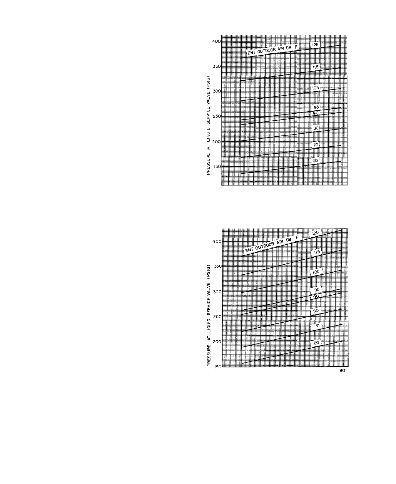
38GR THERMAL EXPANSION VALVE SYSTEMS - Use
Charging Chart, Fig 4 or Fig. 5. See Carrier Standard
Service Techniques Manual, Chapter 1, for procedure.
38SE CAPILLARY TUBE OR ACCURATERTm SYSTEMS
— Use Charging Chart, Fig. 6, and the following procedure;
1. Operate unit a minimum of 10 minutes before checking
charge.
2. Measure suction pressure by attaching a gage to suction
valve service port.
3. Measure suction line temperature by attaching a service
thermometer to unit suction line near compressor.
(Insulate thermometer for accurate readings.)
4. Measure outdoor (condenser inlet) air dry-bulb temper
ature with second thermometer.
5. Refer to Charging Chart (Fig. 6). Find condenser air
temperature and project horizontally to curve showing
suction pressure.
6. From intersect point, project vertically downward to
chart suction line temperature.
7. If unit has a higher suction line temperature than chart,
add refrigerant until chart temperature is reached.
8. If unit has a lower suction line temperature than chart,
bleed refrigerant until chart temperature is reached.
9. If condenser inlet air temperature or unit suction
pressure changes, change to new suction line tem
perature on chart.
Chargemaster® Operation — Operate unit 10 minutes
before using Chargemaster (Carrier Part No. 38GC680004).
1. Tape Chargemaster feeler bulb to suction line close to
condensing unit. Insulate bulb. Ensure suction line is
clean for good contact with bulb.
2. Connect refrigerant drum to Chargemaster inlet port
with drum in position for vapor charging.
3. Connect Chargemaster outlet port to unit suction valve
service port.
4. Crack valves on refrigerant drum and Chargemaster to
purge lines from drum to suction valve. After purging
lines, close valve on Chargemaster only.
5. Measure outdoor air dry-bulb temperature.
f
50 60 70 80 90
PRESSURE AT SUCTION SERVICE VALVE (PSIG)
Fig. 4 - 38GR002,003,004,045,005 Charging Chart -
TXV Systems
50 60 70 80
PRESSURE AT SUCTION SERVICE VALVE (PSIG)
Fig. 5 — 38GR006 Charging Chart — TXV Systems
6. Crack unit suction valve and read evaporator temper
ature at red needle position on Chargemaster temper
ature gage and suction line temperature at black needle
position.
CAOTICA; '
Page 7
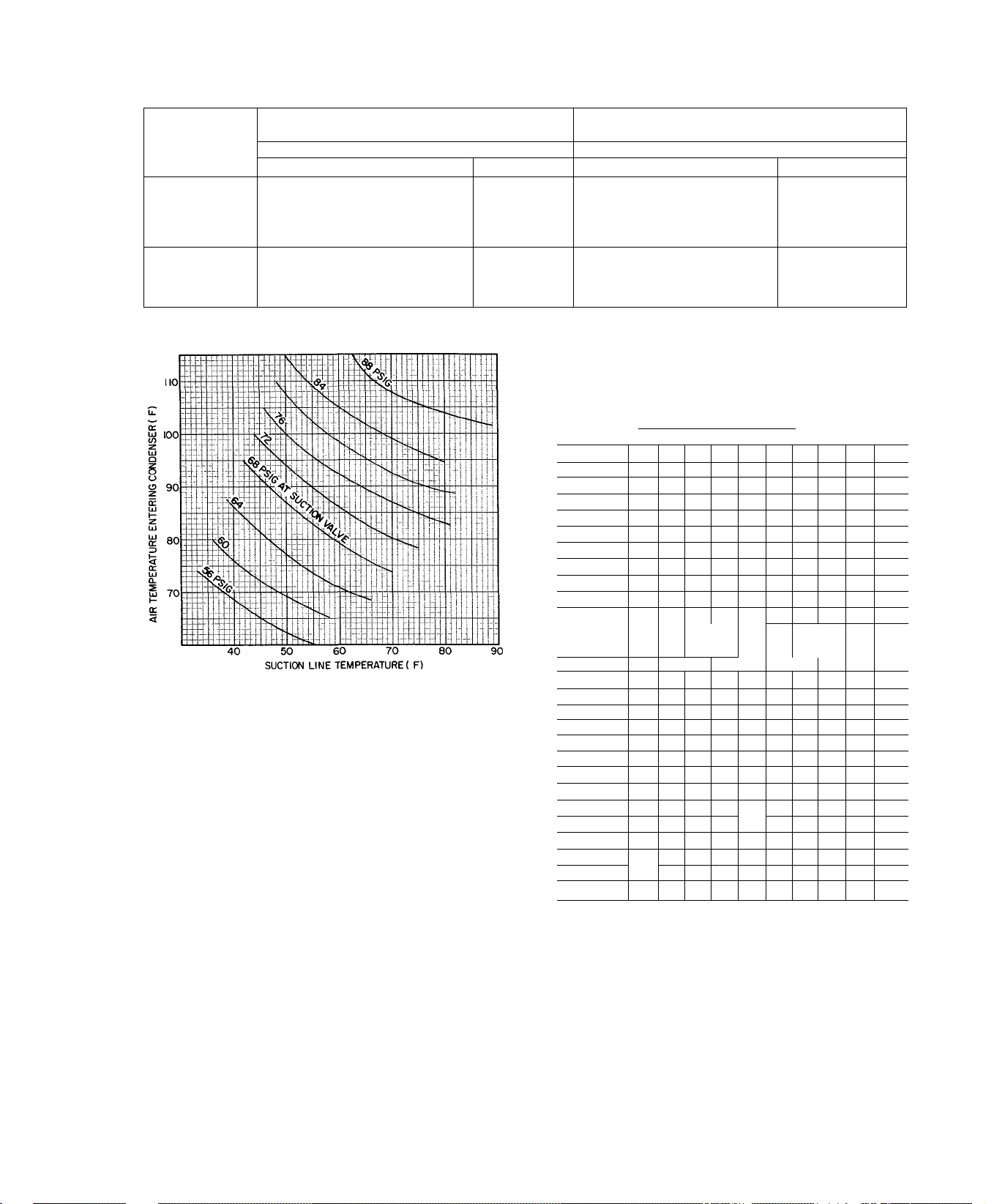
Table 6 — Refrigerant Charging Methods (Carrier Approved Systems)
r
METHODS OF CHECKING
OR ADJUSTING CHARGE
COND UNIT ;
AccuRater^M Capillary Tube
38GR
38SE
NOTE; 38SE operates at lower head pressure than comparable units Do not expect as high pressure when charging or adding charge
System Refriqerant Control
Chargemaster®
Chargemaster
or
Charging Chart
TXV
Charging Chart
er
Sight Glass
Sight Glass
AccuRater Capíllary Tube
COMPLETE RECHARGING
System Refrigerant Control
Weight Method
Plus
Chargemaster
Weight Method
Plus
Chargemaster or
Charging Chart
Table 7 — Chargemaster Charging Chart
(38GR Capillary Tube or AccuRater Systems)
Fig. 6 — 38SE Charging Chart
(Capillary Tube or AccuRater Systems with or
without Suction-Liquid Line Heat Interchange)
7. Enter Chargemaster Charging Chart, Table 7 or 8, at
outdoor air temperature (step 5) and evaporator temper
ature (step 6). Find the suction line temperature
required for correct system charge. If actual suction line
temperature (step 6) is higher than table value, the
system is undercharged. If suction line temperature is
lower than table value, the system is overcharged.
Example: At outdoor air temperature of 85 F and
evaporator temperature of 44 F, the system will be
correctly charged at 71 F ±2 F suction line temperature.
See Table 8.
8. Add charge by slowly opening Chargemaster valve. If
necessary, reduce charge by bleeding at liquid line
service valve. Check outdoor air and evaporator temper
ature during procedure. If they change, refer back to
OUTDOOR
TEMP (F)
60
62
64
66 27 35 45 57
68
70 32
72 31
74
76
78
80
82
m
86
88 35
90
92
94 39
96 38 45
98
100
102
104
106 45 51
108
110
112
114
*Saturated evaporator temperature which is the equivalent tem
perature of pressure taken at the condensing unitsuction service
valve
21 I 25 I 28 I 31 I 34 I 37
32 40
30
38
37 47 60
28
34 43 54 67
30^
29 36 46
27
26
_
Example
Suction Line Temperature table for new value.
Correct use of Chargemaster ensures an optimum refrig
erant charge will be in system when conditions and system
components are normal. However, the Chargemaster does
not solve or fix system abnormalities. It indicates correct
charge for condition of system. It will not make corrections
for dirty filters, slow fans, excessively long or short suction
lines or other abnormal conditions. This charging device
ensures that a correct relationship exists between outdoor
temperature, evaporator temperature, and suction line
temperature on a specific system.
Sight Glass Method — A satisfactory operating charge can
he obtained on thermal expansion valve systems by
charging to a clear sight glass. For optimum charge, elevate
high-side pressure to 380 ±10 psig by blocking condenser
fan discharge or condenser entering air. Charge to a clear
sight glass while holding high-side pressure constant. For
peak efficiency, adjust charge to yield a liquid refrigerant
temperature at the evaporator that is approximately the
same as outdoor dry-bulb temperature.
METHODS FOR
Weight Method
Charging Chart
Sight Glass
Weight Method
Sight Glass
EVAPORATOR TEMP (F)
Ml
43 I 45 48
Suction Line Temperotures
51
49
52 64
41
50 61 72"
39
37 48
35 44 54 63..
33 42
39
29
58 69"
56
52
40
.50
46 55" "63 73 85
37
44 53 61
42
34
41 49 57 65 75 86
33
36
m
66
61 "
w-
51 59 68 78
55 63 72 83
47
53
44
51
42
49 57 65
41
48 55
39 46 53 61
43 49 57 65
41
TXV
Plus
or
Plus
80
76
70
81
70 80
61
59 67 77
63
59 68
55
47
53 61
46
50 59
—
90
75
73
70
63
Page 8
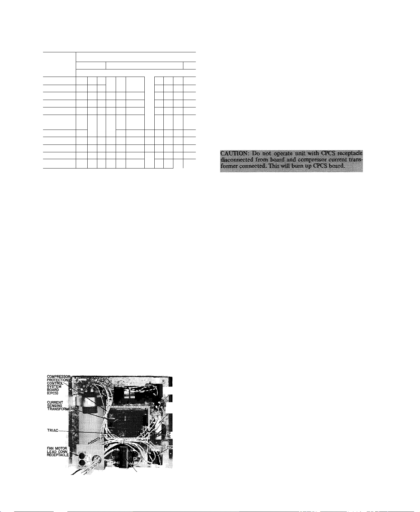
Table 8 — Chargemaster® Charging Chart
(38SE Capillary Tube or AccuRater^'^ Systems)
OUTDOOR
TEMP (F)
60
65
70
75 35
80
"To” '
95
100
105
32| 34136
60
4% 58 65
41 48 58
41 48 58 68
31 36 .42
!
-------
no
115
Example
High-Pressure Relief Valve is located in compressor when so
EVAPORATOR TEMP (F)
38 40 42 im 46 |48 50 52
Suction Line Temperature (F)
— -
68 70
50
44
w.
40w47
59.
42
m
69^
53 j 61
48 53
43 I 47
I 44
--
UNIT PROTECTION
—
82
■■¿9'
78“
59
67
52
58
48 53 60
49
—
79
68
54
50 62
75
65
54
88
104
80
69
equipped. Relief valve opens at a pressure differential of
approximately 450 — 550 psi between suction and discharge.
Valve permits pressure equalization at running condition
described above and during unit shutdown. A hissing sound
during pressure equalization does not indicate bad valves.
High Pressurestat is located on unit liquid line. High
pressurestat settings are; cutout, 425 ± 5 psig; cut-in, 320 ±
20 psig.
Low Pressurestat is located on unit suction line. Low
pressurestat settings are; cutout, 31 ± 4 psig, cut-in, 60
(+15,-0) psig.
Internal Temperature And/Or Current Sensitive Overloads
reset automatically when internal motor temperatures drop
to a safe level (overload may require up to 30 minutes to
reset). When internal overload is suspected of being open,
check by using an ohmmeter or continuity tester. If
necessary, refer to Carrier Standard Service Techniques
Manual, Chapter 2, for complete instructions.
Outdoor Fan Thermostat (38SE055 and 38GR units)
switches fan to high speed (Table 5) when outdoor
temperature reaches 90 F — maintains proper condensing
temperature at high outdoor air temperatures. Thermostat
is located on Control Panel, Fig. 7.
Filter-Drier is installed in liquid line.
FAN THERMOSTAT
«F SO EQUIPPED)
CONTROL
TRANSFORMER
(DUAL SECONDARY)
'CS
CEPTACLE
ITROL RELAY
CONTACTOR
Fig. 7 — Control Panel (Cover Removed)
Compressor Protection Control System (CPCS — Solid
State, Fig. 7) provides; compressor motor locked rotor
protection; compressor start winding protection; compres
sor motor running overload protection; compressor over
temperature protection; contactor anti-chatter protection.
The CPCS also provides for a 4- to 6-minute delay before
restarting compressor after shutdown for any reason. If
compressor loading was light at the moment compressor
was shut off, the delay will be approximately 4 minutes. If
loading was heavy, the delay will be approximately 6
minutes. The CPCS board is located on control panel
beneath a sheet metal protective cover. To troubleshoot the
CPCS, remove protective sheet metal cover, and use unit
label diagram or wiring booklet with Control Circuit
Troubleshooting Chart, page 9.
TROUBLESHOOTING CHART NOTES (Page 9);
1. Ensure thermostat calls for cooling before troubleshooring unit.
2. To disconnect plug from receptacle on CPCS board —
press in tabs located on the receptacle and pull plug
gently while holding tabs. Do not pull on wiring.
3. When performing troubleshooting checks, CPCS recep
tacle must be plugged into CPCS board,
4. Receptacle female connections, which do not grip the
male pin tightly, may be repaired with a small pen knife.
5. When taking meter readings at CPCS receptacle, bottom
meter probe into terminal hole to ensure good electrical
contact.
6. Replace CPCS board if electrical short circuit causes
compressor failure. An electrical short in compressor can
short the triac (electronic switch located on CPCS
board). Triac may fail in a closed (conducting) position
and not open the control circuit.
PUMPDOWN PROCEDURE
The 38GR,SE units may be pumped down in order to
make repairs on low side of system without losing complete
refrigerant charge.
1. Attach pressure gage to suction service valve gage port.
2. Frontseat the liquid line valve.
3. Jumper low-pressure switch.
4. Start unit and run until suction pressure reaches 5 psig
(see Caution).
5. Shut unit off and frontseat suction valve.
6. Vent remaining pressure to atmosphere.
CACTfC^' Thtf 58GR «fill -idd c»nly
suppii&l af
msv icaus« tiKtts 1« syde op pre^pf-
stsi by & djsdtejfgi pfissiiro a
sudifpti rtp? i>i AtOicin" fessfore stis.'ifoi!
reiscte ? ppit, ff sha «¿rctifa, abKi urti! >4i
fipataeat awtsstsi 'tslve vpiit fc-
COMPRESSOR SERVICE
Unit Single-Phase Compressors of the split capacitor (PSC)
type require an equalized system pressure to start. When
supply voltage is within 10% limit and compressor does not
start, give compressor a temporary capacitance boost. See
f
V-
Page 9
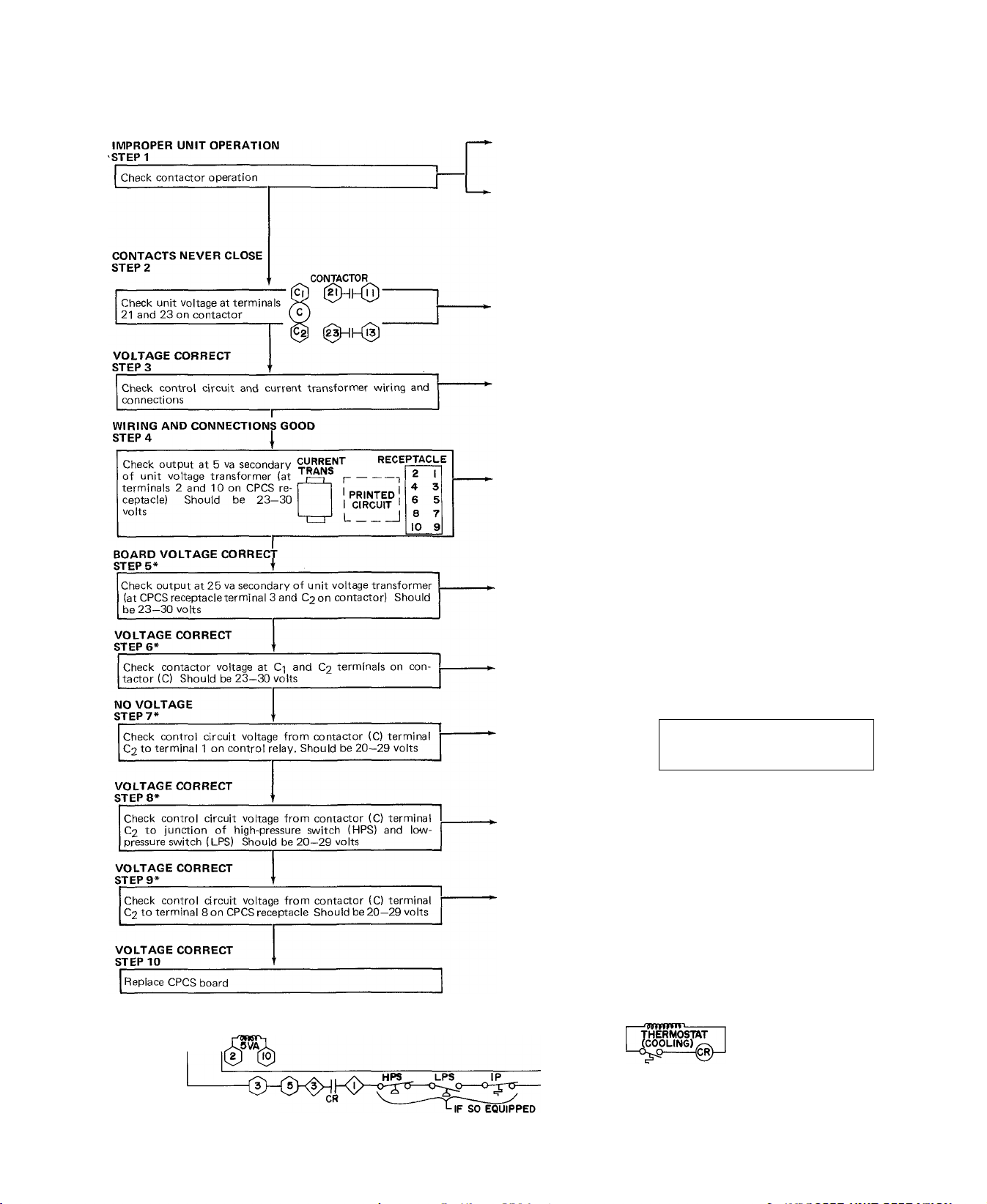
CONTROL CIRCUIT TROUBLESHOOTING CHART
fofs wvi<sa ommxiix^ |b«sC8!^ of isssancaof higff volisga).
sm^ag tssAs^ssrim- & ^ priJiesisiya «¡«tmi sys^era biw<S, Sb«'! ad fea-
Before attempting any corrective action, wait 8 minutes after power is supplied to permit CPCS time delay period to end. If control circuit is
broken and unit has no time delay (or if time deiay is over 8 minutes), repiace CPCS board.
CONTACTS CLOSE
iMMEDiATELY, UNiT
DOES NOT RUN
CONTACTS WON'T STAY
CLOSED. OR, CONTACTS
OPEN BEFORE ROOM ’
THERMOSTAT iS
SATiSFiED
VOLTAGE LOW OR_
NO VOLTAGE
LOOSE CONNECTIONS-
OR IMPROPER WIRING
VOLTAGE LOW OR.
NO VOLTAGE
----------
CPCS Board and control circuit func
►
tion Check compressor, run capacitor,
start gear and internal compressor
protection
Check system pressures and current
draw
Obtain correct voltage
Repair connection or correct wiring
Replace transformer
____ __________
VOLTAGE LOW OR
NO VOLTAGE
VOLTAGE CORRECT-
VOLTAGE IS LOWER.
THAN 20 VOLTSt
VOLTAGE IS LOWER.
THAN 20 VOLTSt
VOLTAGE IS LOWER
THAN 20 VOLTSt
Replace transformer
Replace contactor
Check indoor unit power. indoor
transformer, thermostat or
relay
System pressure too high or bad high-
pressure switch
System pressure too low, bad lowpressure switch or open internal pro
tector (IP)
control
L| L2
I—nfTWWOlWi
2SVA
----
1
TYPICAL CONTROL CIRCUIT
O CPCS Receptacle
o Component Connections
tVoltage reading less than 20 volts may result from feedback circuit.
INDOOR UNIT TRANSFORMER
0—^—0—
TRIAC
Page 10
Carrier Standard Service Techniques Manual, Chapter 2, for
details. Use a 130 mfd start capacitor. Connect wires with
insulated probes to each capacitor terminal. Touch probes
to each side of run capacitor or to compressor motor
terminals R and S. Start compressor; pull probes away after
3 seconds. Discharge start capacitor. Run compressor for 10
minutes, then shut off and allow system pressure to
equalize. Try restarting without boost capacitor. If after 2
attempts (without boost capacitor) the compressor does
not start, add an accessory start capacitor relay package.
Unit Single-Phase Compressors that are equipped with a
compressor start thermistor (PTC device). If compressor
will not start, check the thermistor with an ohmmeter as
follows;
1. Shut off all power to unit and wait 5 minutes for
thermistor to cool to outdoor temperature.
2. Measure resistance of thermistor with ohmmeter.
Normal resistance readings are 50 to 90 ohms at 75 F
outdoor temperature.
3. If ohmmeter resistance reading is 0 or much higher than
90 ohms, the thermistor is defective and must be
replaced.
If start thermistor (PTC device) is good and compressor
will not start, disconnect the thermistor from starting circuit
and give compressor a temporary capacitance boost as
described above. Run compressor for 10 minutes, then shut
off and allow system pressure to equalize. Reconnect start
thermistor and try restarting compressor without boost ca
pacitor. If after 2 attempts the compressor does not start,
remove thermistor and add an accessory start capacitor re
lay package.
Compressor Removal
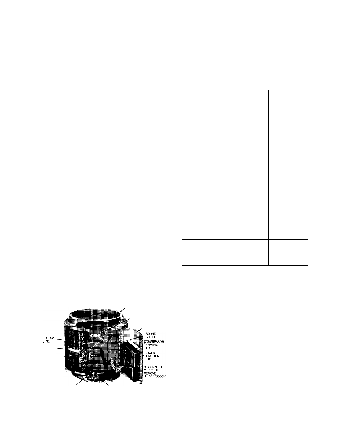
38GR; 38SE002,003,004 UNITS - See Table 9 for
compressor information and Fig. 8 for component location.
Shut off power to unit. Vent refrigerant to atmosphere or
use refrigerant removal methods shown in Carrier Standard
Service Techniques Manual, Chapter 1.
1. Remove unit top cover (grille). Open or remove service
door.
2. Disconnect fan motor leads from control panel located
on service door. See Fig. 7 and refer to Service Door on
page 3. Remove 6 screws holding fan motor orifice
assembly in place and lift assembly from unit.
3. Compressor outer sound shield is fastened to tube sheets
and to base pan. Loosen screws and remove sound shield
by sliding it straight up using tube sheets as guides.
4. (38SE only) — Warp top cover of inner compressor
sound shield upward to clear compressor process tube.
Carefully slide cover over the tubing.
.TOP GRILLE COVER
FAN MOTOR-ORIFICE
ASSEMBLY
SERVICE
DOOR
SUCTION
LINE
COMPRESSOR
JCONTROL
LIQUID VALVE
SERVICE PORT
SUCTION VALVE
SERVICE PORT
Fig. 8 — 38GR Condensing Unit with Service Door Open
»PANEL
COVER
5. (38SE only) — Slide inner compressor sound shield
terminal box cover upward and out.
6. Remove compressor terminal box cover, disconnect and
remove compressor power leads.
7. (38SE only) — Lift off inner compressor sound shield.
8. Unsweat suction and hot-gas lines.
9. Remove compressor hold-down bolts. Lift compressor
out thru top of unit.
Table 9 — Compressor Data
COND
UNIT
38GR002--38GR002320
38GR003--38GR0033I0
38GR004--38GR0043IO
38GR045--- PC4Ó26AD 76 0
38GR005--- PC5326AD 76.0
38GR006--- PC6725AB 76 0
38GR003--38GR0034Í0
38GR004--- RF3922CJ
38GR0044Í0
38GR045--38GR0£)5--38GR006--- PF6725AA 76 0
38GR003--- RG3522CJ
38GR0035I0
38GR004---
38GR0045Í0
38GR045---
38GR005---
38GR006---
38GR004---
38GR0046Í0
38GR045--- 460/3
38GR005---
38GR006---
38SE002---
38SE003--- MD2723CB
38SE004---
38SE045---
38SE055--- PC5326AD
shown italicized 000.
* Refer to Service Parts catalog for replacement compressor model
numbers. The 38GR.SE single-phase compressors include start
assist.
V/PH
230/1*
200/3
230/3
230/1 MC3423CB
PRODUCTION
COMPRESSOR*
38GL400324
MD2723CB
38GR400234 31.5
MC3423CB 43.2
38GC401564
MC4023CB 43.2
RF3522CJ
MF3423CB
MF4023CB
PF4626AD
PF5326AD
MG3423CB
RG3922CJ
MG4023CB
PG4626AD
PG5326AD 76 0
PG6725AA 76 0
RH3922CJ
MH4023CB
PH4626AD
PH5326AD
PH6725AA
MD2023CB
PC4Ó26AD 76 0
OIL RECHARGE
(oz)
40.5
43.2
45.0
50.4
43 2
50 4
43.2
76.0
76.0
50.4
43 2
50.4
43.2
76.0
50 4
43 2
76.0
76.0
76.0
43 2
43.2
43.2
76.0
38SE045,055 UNITS
1. Open and remove service door. See Fig. 7 and refer to
Service Door on page 3.
2. Disconnect fan motor leads and crankcase heater leads
from control panel located on service door.
3. Remove cover plate on compressor terminal box and
disconnect all leads.
4. Remove 4 screws holding compressor plastic sound
shield in place. Slide shield upward 6 to 10 inches.
5. Unsweat suction and hot-gas lines at compressor (dis
connect convenient connection at sight glass or filterdrier).
6. Remove 3 screws holding coil to base pan.
7. From front of unit (coil-emblem side) hft complete
disconnected coil-fan-top cover assembly off from
compressor-base pan assembly.
10
Page 11
8. Remove compressor from base pan and replace with new
compressor. Install crankcase heater (step 2) on new
compressor.
9. Replace coil-fan-top cover assembly on compressor-base
pan assembly; reconnect all joints and wiring; recharge
unit.
COMPATIBLE FITTING REPAIR
Leaking Mechanical Connection — Frontseat condensing
unit service valves and reheve refrigerant pressure in tubing.
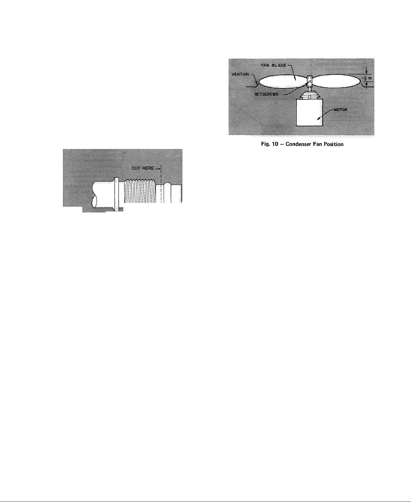
Back locknut off compatible fitting onto tube. Cut fitting
between threads and seal ring head as shown in Fig. 9.
Remove tubing section remaining in threaded portion of
fitting. Discard locknut.
Clean, flux, and insert new tube end into remaining por
tion of compatible fitting. Wrap valve base in wet rag. Heat
and apply low-temperature (450 F) solder.
Fig. 9 — Repair of Mechanical Connection
Metal Fan — Required fan position is shown in Fig. 10.
Adjust fan by loosening setscrew and moving fan blades up
or down.
Fan Motor Removal
1. Shut off power to unit.
2 Remove unit top cover (grille). Open or remove service
door. With door open, remove control panel cover.
3. Disconnect fan motor leads (3) from control panel
located on service door. See Fig. 7.
4. Remove fan from motor shaft by loosening setscrew and
pulling upward on fan hub.
5. Remove bolt holding fan motor to motor mounting
bracket. Remove motor with wiring thru top of unit. To
replace motor, place motor on self-positioning motor
mounting bracket and retighten bolt.
Before replacing metal fan, be sure moisture protectors
are in place on motor shaft.
Leaking Sweat Connection — Frontseat service valves and
relieve refrigerant pressure in tubing. Clean and flux area
around leak and apply low-temperature (450 F) solder.
Evacuate or purge evaporator coil and tubing system.
Add refrigerant charge (see charging instmctions).
CONDENSER
Coil Cleaning — Ensure power to unit is shut off. Clean the
condensing unit coil at the beginning of every cooling
season or more often if required. Use ordinary garden hose
at a pressure high enough to clean efficiently. For best
results, unscrew and remove unit top cover (grille). Insert
hose nozzle between fan blades and spray coil fins from
inside-to-outside the unit. If unit has a double-row coil,
loosen screws to separate coils, and flush dirt toward
outside of both coils. Flush dirt from base pan by spraying
water thru top of unit. Avoid splashing mud on coil or
water on the fan motor.
LUBRICATION
Fan Motor Bearings — OiUng holes are provided at each end
of condenser fan motor. Remove fan motor and lubricate
motor with 32 drops (16 drops per hole) of SAE-10
nondetergent oil at intervals described below
a. Annually, when environment is very dirty, ambient
temperature is higher than 105 F, and average unit
operating time exceeds 15 hours a day.
b. Every 3 years when environment is reasonably clean,
ambient temperature is less than 105 F and unit
operating time averages 8 to 15 hours a day.
c. Every 5 years when environment is clean, ambient
temperature is less than 105 F and unit operating time
averages less than 8 hours a day.
Compressor contains factory oil charge. When oil is lost, see
Table 9 for oil recharge and Carrier Standard Service
Techniques Manual, Chapter 1, page 1-21, for instructions.
Use Carrier PP33-1, Texaco Capella B or Suniso 3G oil.
11
Page 12
Condenser Fan On
Condenser Air Restricted
Condenser Air Recirculating
Noncondensables in System
Refrigerant Overcharge
Improper Line Voltage
Refrigerant System Restriction
Loose Electric Connections
Faulty Run Capacitor
Condenser Fan Off
Fan Slipping on Shaft
Loose Electric Connections
Fan Motor Overload Open
Fan Motor Bearings Stuck
Fan Motor Defective
Low Suction Pressure
Low Refrig Charge
High Suction Pressure
Low Head Pressure
Defective Compressor Valves
Slightly Low Suction Pressure
Dirty Filters
Partially Restricted Airflow
Coil Partially Iced
Slightly Low on Refrigerant
Duct Restricted
Dampers Partially Closed
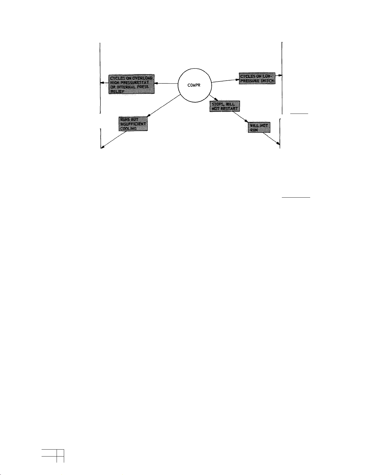
TROUBLESHOOTING CHART*
Evaporative Fan Running
Low Refrig Charge
Restricted Refrig Flow
Restricted Capillary
Defective TXV
Restricted Evaporator Air
Dirty or Iced Coil
Plugged Filter
Dampers Closed
Restricted Ductwork
Evaporator Fan Stopped
Defective Fan Relay
Loose Leads
Overload Open
Burned Out Motor
Broken Belt
Contactor Open
Dead Transformer
Thermostat Circuit Open
Faulty Control Relay
Overload Open
Contactor Coil Open
Loose Connection
Contactor Closed
Loose Leads at Compressor
Loose Leads at Contactor
Motor Windings Open
Internal Compr Overload Open
Contactor Closed, Then Opens
Overload Opens
Faulty CPCS Boord
_____________
Compressor Stuck
______________
*To troubleshoot control circuit, see Control Circuit Troubleshooting Chart, page 9.
For replacement items use Carrier Specified Parts.
Manufacturer reserves the right to discontinue, or change at any time, specifications or designs without notice and without incurring obligations.
Tab 4
Form 38SE-3S1 Supersedes 38GR-3SI, 38SE-2SI Printed in U S.A 1076
3-75 PC 101 Catalog No. 533-827
1 Book 1
3a
1 Tab
 Loading...