


38MFQ0123
Product Data
40MFC / 38MFC
40MFQ / 38MFQ
High---Wall Ductless Split System
Sizes 09 to 22
INDUSTRY LEADING
FEATURES / BENEFITS
A PERFECT BALANCE BETWEEN
BUDGET LIMITS, ENERGY SAVINGS AND
COMFORT.
The 38/40MFC(Q) series ductless split systems are a matched
combination of an outdoor condensing unit and an indoor fan coil
unit connected only by refrigerant tubing and wires.
The fan coil is mounted on the wall, near the ceiling. This
selection of fan coils permits creative solutions to design problems
such as:
S Add--ons to current space (an office or family room
addition)
S Special space requirements
S When changes in the load cannot be handled by the
existing system.
S When adding air conditioning to spaces that are heated
by hydronic or electric heat and have no ductwork.
S Historical renovations or any application where
preserving the look of the original structure is essential.
The ideal compliment to your ducted system when it is impractical
or prohibitively expensive to use ductwork.
These compact indoor fan coil units take up very little space in the
room and do not obstruct windows. The fan coils are attractively
styled to blend with most room decors. Advanced system
components incorporate innovative technology to provide reliable
cooling performance at low sound levels.

2
LOW SOUND LEVELS
When noise is a concern, the ductless split systems are the answer.
The indoor units are whisper quiet. There are no compressors
indoors, either in the conditioned space or directly over it, and
there is none of the noise usually generated by air being forced
through ductwork.
When sound ordinances and proximity to neighbors demand quiet
operation, the 38MFC,MFQ unit is the right choice: The advanced,
horizontal airflow design distributes air more evenly over the coil.
SECURE OPERATION
If security is an issue, outdoor and indoor units are connected only
by refrigerant piping and wiring to prevent intruders from crawling
through ductwork. In addition, since 38MFC,MFQ units can be
installed close to an outside wall, coils are protected from vandals
and severe weather.
FAST INSTALLATION
This compact ductless split system is simple to install. A mounting
bracket is standard with the indoor units and only wire and piping
need to be run between indoor and outdoor units. These units are
fast and easy to install ensuring minimal disruption to customers in
the home or workplace. This makes the 38/40MFC,MFQ ductless
split systems the equipment of choice, especially in retrofit
situations.
SIMPLE SERVICING AND
MAINTENANCE
Removing the top panel on outdoor units provides immediate
access to the control compartment, providing a service technician
access to check unit operation. In addition, the draw--thru design of
the outdoor section means that dirt accumulates on the outside
surface of the coil. Coils can be cleaned quickly from the inside
using a pressure hose and detergent.
On all indoor units, service and maintenance expense is reduced
due to easy--to--use cleanable filters. In addition, these high wall
systems have extensive self--diagnostics to assist in
troubleshooting.
BUILT--IN RELIABILITY
Ductless split system indoor and outdoor units are designed to
provide years of trouble--free operation.
The high wall indoor units include protection against freeze--up
and high evaporator temperatures on heat pumps.
The condensing units on heat pumps are protected by a three
minute time delay before the compressor will start the over--current
protection and the high temperature protection.
INDIVIDUAL ROOM COMFORT
Maximum comfort is provided because each space can be
controlled individually based on usage pattern. The air sweep
feature provided permits optimal room air mixing to eliminate hot
and cold spots for occupant comfort. In addition, year--round
comfort can be provided with heat pumps.
ECONOMICAL OPERATION
The ductless split system design allows individual room heating or
cooling when required. There is no need to run large supply--air
fans or chilled water pumps to handle a few spaces with unique
load patterns. In addition, because air is moved only in the space
required, no energy is wasted moving air through ducts.
EASY--TO--USE CONTROLS
The high-- wall units have microprocessor-- based controls to
provide the ultimate in comfort and efficiency. The user friendly
wireless remote control provides the interface between user and the
unit.
ACCESSORIES
Customizing these ductless split systems to your application is
easily accomplished.
Adding a condensate pump accessory to the high wall fan coil
provides installation flexibility.
OPTIONAL WIRED CONTROLLER
AGENCY LISTINGS
All systems are listed with AHRI (Air Conditioning, Heating &
Refrigeration Institute), and ETL.
3
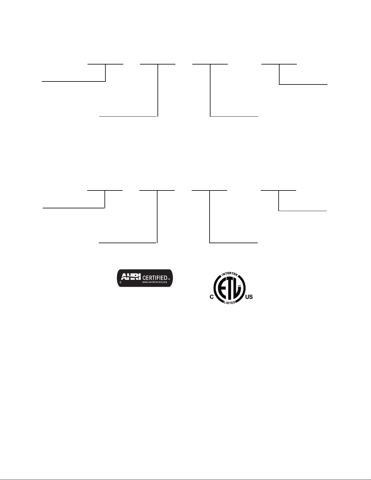
MODEL NUMBER NOMENCLATURE
OUTDOOR UNIT
38 MFC 1
--- --- ---
009
38 = Ai r --- C o o l e d C o n d e n s e r
Unit Type
MFC --- Coolin g O n l y
MFQ --- Hea t P u m p
Volt age
1--- 1 1 5 --- 1 --- 6 0
3--- 2 0 8 --- 2 3 0 --- 1 --- 6 0
INDOOR UNIT
40 MFC 1
--- --- ---
009
40= Fan Coil Un it
Unit Type
MFC --- Coolin g O n l y
MFQ --- Hea t P u m p
Volt age
1 --- 1 1 5 --- 1 --- 6 0
3 --- 2 0 8 --- 2 3 0 --- 1 --- 6 0
Nominal Capacity
009 --- 3/ 4 To n
012 --- 1 T o n
017 --- 1 --- 3/7 T o n (HP)
018 --- 1 --- 1/2 T o n (AC )
022 --- 1 --- 5/6 T o n s
Nominal Capacity
009 --- 3/ 4 To n
012 --- 1 T o n
017 --- 1 --- 3/7 T o n (HP)
018 --- 1 --- 1/2 T o n (AC )
022 --- 1 --- 5/6 T o n s
Use of the AHRI Certified
TM Mark indicates a
manufacturer’s
participation in the
program For verification
of certification for individual
products, go to
www.ahridirectory.org.
4
STANDARD FEATURES AND ACCESSORIES
Ease Of Installation
Mounting Brackets S
Low Voltage Controls S
Comfort Features
Microprocessor Controls S
Wired Remote Control A
Wireless Remote Control S
Automatic Horizontal Air Sweep S
Air Direction Control S
Auto Restart Function S
Cold Blow Protection On Heat Pumps S
Freeze Protection Mode On Heat Pumps S
Turb o Mode S
Silence Mode S
Auto Changeover On Heat Pumps S
Energy Saving Features
Sleep Mode S
Stop/Start Timer S
Safety And Reliability
3MinuteTimeDelayForCompressor S
Over Current Protection For Compressor S
Indoor Coil Freeze Protection S
Indoor Coil High Temp Protection in Heating Mode S
Condenser High Temp Protection in Cooling Mode S
Ease Of Service And Maintenance
Cleanable Filters S
Diagnostics S
Liquid Line Pressure Taps S
Application Flexibility
Condensate Pumps A
Crankcase Heater S
Legend
SStandard
A Accessory
INDOOR UNITS
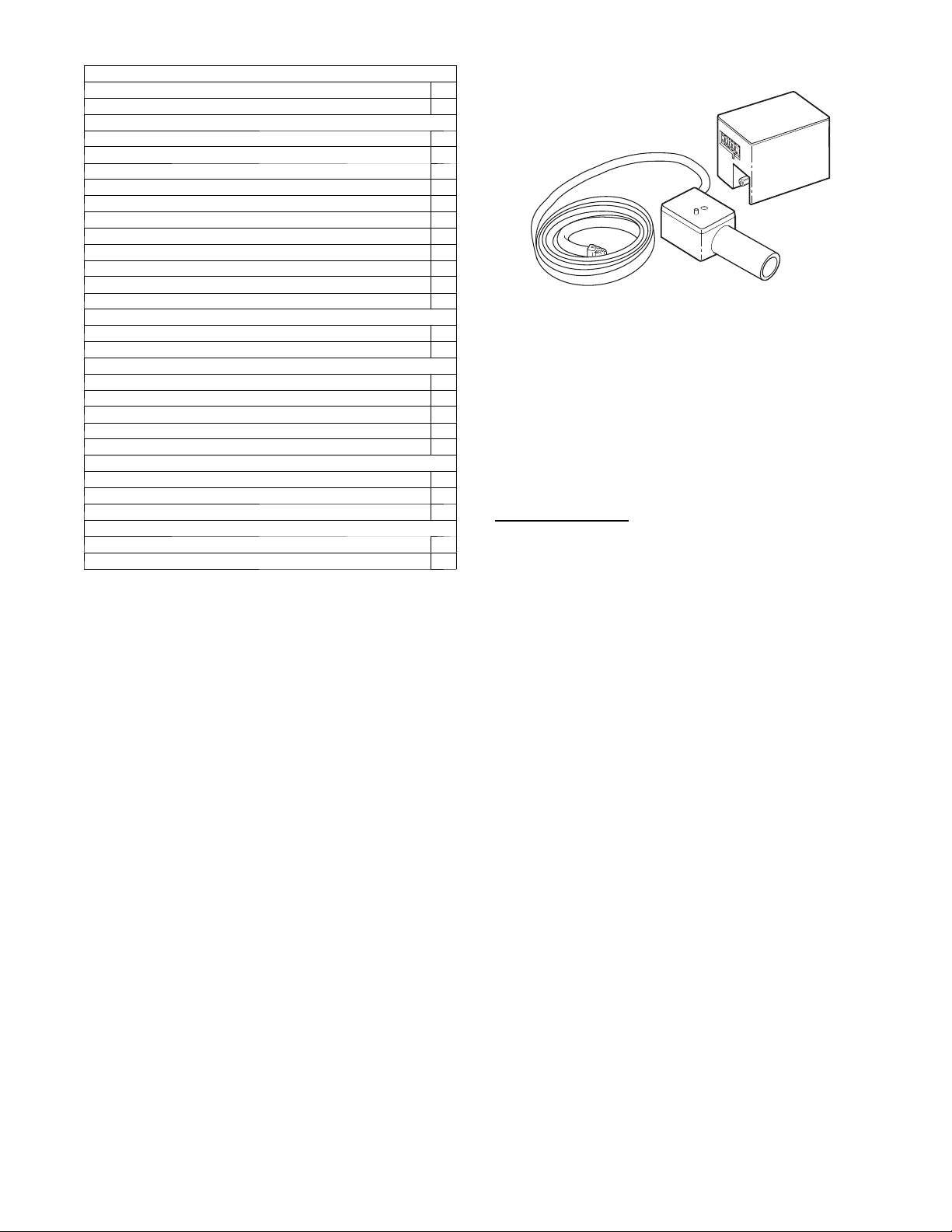
A07892
Fig. 1 – Condensate Pump Accessory
On high wall fan coils, the condensate pump has a lift capability of
12 ft (3.6 m) on the discharge side with the pump mounted in the
fan coil or 6 ft (1.8 m) on the suction side if the pump is remote
mounted. The pump is recommended when adequate drain line
pitch cannot be provided, or when the condensate must move up to
exit.
NOTE: An external 115v power source will be required to run the
pump on unit sizes 9k and 12k.
OUTDOOR UNITS
Crankcase Heater
Standard on all unit sizes. Heater clamps around compressor oil
stump.
5
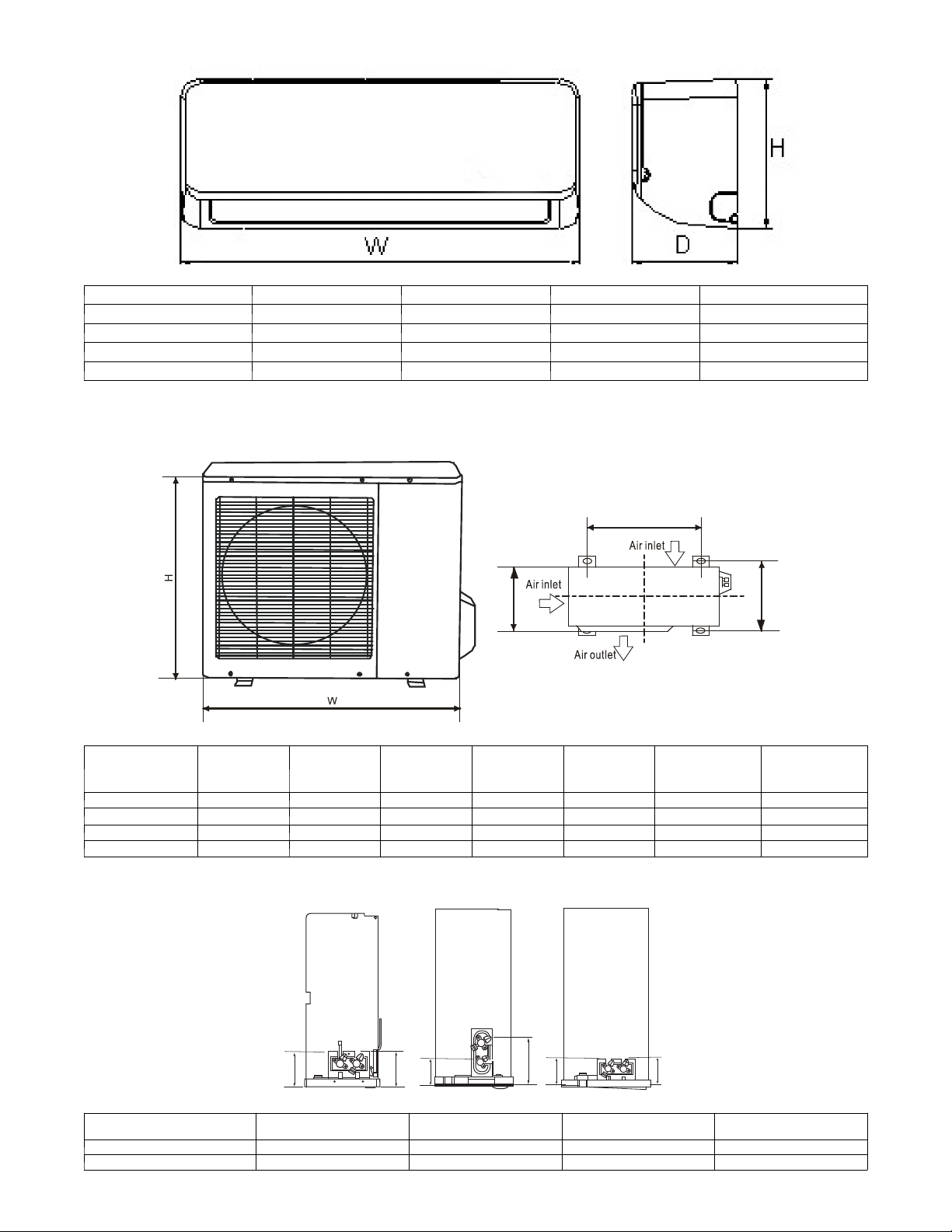
DIMENSIONS -- INDOOR
A14343
Unit Size W in (mm) D in (mm) H in (mm) Operating Weight lb (kg)
9K 26.8 (680) 7.0 (178) 10.0 (255) 15.4 (7)
12K 30.3 (770) 7.4 (188) 10.0 (255) 16.5 (7.5)
17K HP / 18K AC 35.6 (905) 7.8 (198) 10.8 (275) 19.8 (9)
22K 40.6 (1030) 8.6 (218) 12.4 (315) 26.4 (12)
DIMENSIONS -- OUTDOOR
L2
L1
D
A14344
Model W in (mm) D in (mm) H in (mm) L1 in (mm) L2 in (mm)
HP
Operating
Weight lb (kg)
AC
Operating
Weight lb (kg)
9K 30.7 (780) 9.8 (250) 21.2 (540) 21.6 (549) 10.9 (276) 70.5 (32.0) 58.4 (26.5)
12K 30.7 (780) 9.8 (250) 21.2 (540) 21.6 (549) 10.9 (276) 70.5 (32.0) 61.7 (28.0)
17K HP / 18K AC 29.9 (760) 11.2 (285) 23.2 (590) 20.9 (530) 11.4 (290) 82.7 (37.5) 76.0 (47.0)
22K 33.3 (845) 12.6 (320) 27.6 (700) 22.0 (560) 13.2 (335) 103.6 (47.0) 98.1 (44.5)
SERVICE VALVE LOCATIONS
J
K
9/12K
17/18K
22K
J
K
J
K
A14408
Service Valve Locations
9K
in. (mm)
12K
in. (mm)
18K
in. (mm)
22K
in. (mm)
J 4.37 (111) 4.37 (111) 4.09 (104) 4.13 ( 105)
K 4.61 (117) 4.61 (117) 6.34 (161) 4.13 (105)
6
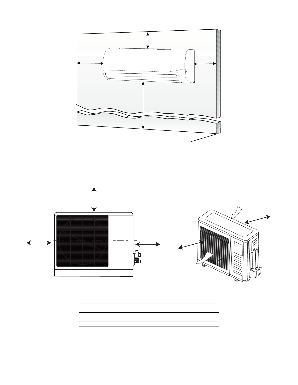
CLEARANCES -- INDOOR
6
"
(0.15m
)
min.
5
"
(0.13m)
min.
6'
5
"
(0.13m)
min.
(1.8m)
CEILING
FLOOR
A07891
Fig. 2 – Indoor Unit Clearance
CLEARANCES -- OUTDOOR
A
D
B
Air-outlet
Air-inlet
C
E
A07894
UNIT
Minimum Value
in. (mm)
A 24 (610)
B 24 (610)
C 80 (2032)
D 12 (305)
E 24 (610)
Fig. 3 – Outdoor Unit Clearance
 Loading...