


 Loading...
38MHRB
Outdoor Unit Single Zone Ductless System Sizes 09 to 24
Service Manual
TABLE OF CONTENTS
PAGE SAFETY CONSIDERATIONS . . . . . . . . . . . . . . . . . . . . . . . . . 1 INTRODUCTION . . . . . . . . . . . . . . . . . . . . . . . . . . . . . . . . . . . 1 MODEL/SERIAL NUMBER NOMENCLATURES . . . . . . . . . 2 SPECIFICATIONS . . . . . . . . . . . . . . . . . . . . . . . . . . . . . . . . . . . 3 DIMENSIONS . . . . . . . . . . . . . . . . . . . . . . . . . . . . . . . . . . . . . 5 CLEARANCES . . . . . . . . . . . . . . . . . . . . . . . . . . . . . . . . . . . . . 8 ELECTRICAL DATA . . . . . . . . . . . . . . . . . . . . . . . . . . . . . . . . 9 WIRING . . . . . . . . . . . . . . . . . . . . . . . . . . . . . . . . . . . . . . . . . . . 9 CONNECTION DIAGRAMS . . . . . . . . . . . . . . . . . . . . . . . . . 10 WIRING DIAGRAMS . . . . . . . . . . . . . . . . . . . . . . . . . . . . . . . 11 REFRIGERATION CYCLE DIAGRAMS . . . . . . . . . . . . . . . . 17 REFRIGERANT LINES . . . . . . . . . . . . . . . . . . . . . . . . . . . . . 18 SYSTEM EVACUATION AND CHARGING . . . . . . . . . . . . . 19 ELECTRONIC FUNCTIONS . . . . . . . . . . . . . . . . . . . . . . . . . 18 TROUBLESHOOTING . . . . . . . . . . . . . . . . . . . . . . . . . . . . . . 23 OUTDOOR UNIT DIAGNOSTIC GUIDES . . . . . . . . . . . . . . 24 PCB DIAGRAMS . . . . . . . . . . . . . . . . . . . . . . . . . . . . . . . . . . 25 DIAGNOSIS AND SOLUTION . . . . . . . . . . . . . . . . . . . . . . . 27 DISASSEMBLY INSTRUCTIONS . . . . . . . . . . . . . . . . . . . . . 48 APPENDIX . . . . . . . . . . . . . . . . . . . . . . . . . . . . . . . . . . . . . . . 71
SAFETY CONSIDERATIONS
Installing, starting up, and servicing air−conditioning equipment can be hazardous due to system pressures, electrical components, and equipment location (roofs, elevated structures, etc.).
Only trained, qualified installers and service mechanics should install, start−up, and service this equipment.
Untrained personnel can perform basic maintenance functions such as cleaning coils. All other operations should be performed by trained service personnel.
When working on the equipment, observe precautions in the literature and on tags, stickers, and labels attached to the equipment.
Follow all safety codes. Wear safety glasses and work gloves. Keep quenching cloth and fire extinguisher nearby when brazing. Use care in handling, rigging, and setting bulky equipment.
Read this manual thoroughly and follow all warnings or cautions included in literature and attached to the unit. Consult local building codes and National Electrical Code (NEC) for special requirements.
Recognize safety information. This is the safety−alert symbol !! . When you see this symbol on the unit and in instructions or manuals, be alert to the potential for personal injury. Understand these signal words: DANGER, WARNING, and CAUTION.
These words are used with the safety−alert symbol. DANGER identifies the most serious hazards which will result in severe personal injury or death. WARNING signifies hazards which could result in personal injury or death. CAUTION is used to identify unsafe practices which may result in minor personal injury or product and property damage. NOTE is used to highlight suggestions which will result in enhanced installation, reliability, or operation.
!WARNING
ELECTRICAL SHOCK HAZARD
Failure to follow this warning could result in personal injury or death.
Before installing, modifying, or servicing system, main electrical disconnect switch must be in the OFF position. There may be more than 1 disconnect switch. Lock out and tag switch with a suitable warning label.
!WARNING
EXPLOSION HAZARD
Failure to follow this warning could result in death, serious personal injury, and/or property damage.
Never use air or gases containing oxygen for leak testing or operating refrigerant compressors. Pressurized mixtures of air or gases containing oxygen can lead to an explosion.
!CAUTION
EQUIPMENT DAMAGE HAZARD
Failure to follow this caution may result in equipment damage or improper operation.
Do not bury more than 36 in. (914 mm) of refrigerant pipe in the ground. If any section of pipe is buried, there must be a 6 in. (152 mm) vertical rise to the valve connections on the outdoor units. If more than the recommended length is buried, refrigerant may migrate to the cooler buried section during extended periods of system shutdown. This causes refrigerant slugging and could possibly damage the compressor at start−up.
INTRODUCTION
This Service Manual provides the necessary information to service, repair, and maintain the outdoor units. Section 2 of this manual has an appendix with data required to perform troubleshooting. Use the Table of Contents to locate a desired topic.

MODEL/SERIAL NUMBER NOMENCLATURES
Table 1—Unit Sizes
|
SYSTEM TONS |
BTUh |
VOLTAGE - PHASE |
OUTDOOR MODEL |
|
1.00 |
12,000 |
115-1 |
38MHRBC12AA1 |
Cooling Only |
1.00 |
12,000 |
208/230-1 |
38MHRBC12AA3 |
|
1.50 |
18,000 |
208/230-1 |
38MHRBC18AA3 |
|
2.00 |
24,000 |
208/230-1 |
38MHRBC24AA3 |
|
1.00 |
12,000 |
115-1 |
38MHRBQ12AA1 |
|
0.75 |
9,000 |
208/230-1 |
38MHRBQ09AA3 |
Heat Pump |
1.00 |
12,000 |
208/230-1 |
38MHRBQ12AA3 |
|
1.50 |
18,000 |
208/230-1 |
38MHRBQ18AA3 |
|
2.00 |
24,000 |
208/230-1 |
38MHRBQ24AA3 |
OUTDOOR UNIT
38 |
MH |
R |
B |
Q |
38 = OUTDOOR UNIT
MH = MODEL
UNIT TYPE
R = OUTDOOR UNIT
MAJOR SERIES
SYSTEM TYPE
C = COOLING ONLY
Q = HEAT PUMP
01 18
Week of Manufacture
Year of Manufacture
09 |
A |
A |
3 |
VOLTAGE
1 =115-1-60
3 = 208/230-1-60
VARIATIONS
A = STANDARD
MAXIMUM NUMBER OF FAN COIL UNITS THAT
CAN BE CONNECTED TO THE OUTDOOR UNIT
A = 1:1
NOMINAL CAPACITY 09 - 3/4 TON
12 - 1 TON
18 - 1-1/2 TONS
24 - 2 TONS
V 10001
Sequential Serial Number
V = ALL MODELS
Use of the AHRI Certified TM Mark indicates a manufacturer’s participation in the program For verification
of certification for individual products, go to www.ahridirectory.org.
2

SPECIFICATIONS
Table 2—Specifications (Cooling Only)
System |
Size |
|
12 |
12 |
18 |
24 |
|
Outdoor Model |
|
38MHRBC12AA1 |
38MHRBC12AA3 |
38MHRBC18AA3 |
38MHRBC24AA3 |
||
|
|
||||||
|
Voltage, Phase, Cycle |
V/Ph/Hz |
115-1-60 |
208/230-1-60 |
208/230-1-60 |
208/230-1-60 |
|
Electrical |
MCA |
A. |
13 |
11 |
15 |
18 |
|
|
MOCP - Fuse Rating |
A. |
20 |
15 |
20 |
25 |
|
Operating |
Cooling Outdoor DB |
°F (°C) |
0~122 (-17~50) |
0~122 (-17~50) |
0~122 (-17~50) |
0~122 (-17~50) |
|
Range |
Min - Max |
||||||
|
|
|
|
|
|||
|
Total Piping Length |
ft (m) |
82 (25) |
82 (25) |
98 (30) |
164 (50) |
|
|
Piping Lift* |
ft (m) |
33 (10) |
33 (10) |
66 (20) |
66 (20) |
|
Piping |
Pipe Connection |
in (mm) |
1/4 (6.35) |
1/4 (6.35) |
1/4 (6.35) |
3/8 (9.52) |
|
Size - Liquid |
|||||||
|
|
|
|
|
|
||
|
Pipe Connection |
in (mm) |
1/2 (12.7) |
1/2 (12.7) |
1/2 (12.7) |
5/8 (16) |
|
|
Size - Suction |
||||||
|
|
|
|
|
|
||
|
Type |
|
R410A |
R410A |
R410A |
R410A |
|
Refrigerant |
Charge |
lbs (kg) |
1.30 (0.59) |
1.17 (0.53) |
1.98 (0.90) |
2.56 (1.16) |
|
|
Metering Device |
|
EEV |
EEV |
EEV |
EEV |
|
|
Face Area |
Sq. Ft. |
4.15 |
4.15 |
4.15 |
4.78 |
|
Outdoor Coil |
No. Rows |
|
1 |
1 |
2 |
2 |
|
Fins per inch |
|
22 |
22 |
22 |
22 |
||
|
Circuits |
|
2 |
2 |
4 |
6 |
|
|
Type |
|
Rotary Inverter |
Rotary Inverter |
Rotary Inverter |
Rotary Inverter |
|
|
Model |
|
ASN98D22UFZ |
ASK89D29UEZD |
ASN140D21UFZ |
ATN150D30UFZA |
|
Compressor |
Oil Type |
|
VG74 |
VG74 |
VG74 |
VG74 |
|
|
Oil Charge |
Fl. Oz. |
13.0 |
13.0 |
15.5 |
23.6 |
|
|
Rated Current |
RLA |
9.5 |
6.8 |
9.0 |
12.0 |
|
|
Unit Width |
in (mm) |
30.31 (770) |
30.31 (770) |
30.31 (770) |
33.27 (845) |
|
|
Unit Height |
in (mm) |
21.85 (555) |
21.85 (555) |
21.85 (555) |
27.64 (702) |
|
Outdoor |
Unit Depth |
in (mm) |
11.81 (300) |
11.81 (300) |
11.81 (300) |
14.29 (363) |
|
Net Weight |
lbs (kg) |
57.8 (26.2) |
53.8 (24.4) |
65.9 (29.9) |
88.6 (40.2) |
||
|
|||||||
|
Airflow |
CFM |
1,170 |
1,230 |
1,195 |
1,825 |
|
|
Sound Pressure |
dB(A) |
52.0 |
53.6 |
55.3 |
58.0 |
Compatibility
Table 3—Compatibility
|
Indoor Unit |
38MHRBC12AA1 38MHRBC12AA3 38MHRBC18AA3 38MHRBC24AA3 |
|||
|
|
|
|
|
|
|
40MHHC12---1 |
● |
|
|
|
High Wall |
40MHHC12---3 |
|
● |
|
|
40MHHC18---3 |
|
|
● |
|
|
|
|
|
|
||
|
40MHHC24---3 |
|
|
|
● |
|
|
|
|
|
|
Performance
Table 4—Performance
Indoor Model |
|
40MHHC12---1 40MHHC12---3 40MHHC18---3 40MHHC24---3 |
|||
Energy Star |
|
NO |
NO |
NO |
NO |
Cooling System Tons |
|
1.0 |
1.0 |
1.4 |
1.8 |
High Wall Cooling Rated Capacity |
Btu/h |
12,000 |
11,500 |
17,000 |
22,000 |
Cooling Cap. Range Min - Max |
Btu/h |
4,800~13,200 |
4,800~13,000 |
5,800~18,600 |
4,900~24,100 |
SEER |
|
17.3 |
19.0 |
19.0 |
18.5 |
EER |
|
10.7 |
11.2 |
10.3 |
11.1 |
3

SPECIFICATIONS (CONT)
Table 5—Specifications (Heat Pump)
System |
Size |
|
12 |
9 |
12 |
18 |
24 |
|
Outdoor Model |
|
38MHRBQ12AA1 38MHRBQ09AA3 38MHRBQ12AA3 38MHRBQ18AA3 38MHRBQ24AA3 |
||||||
|
|
|||||||
|
Voltage, Phase, Cycle |
V/Ph/Hz |
115-1-60 |
208/230-1-60 |
208/230-1-60 |
208/230-1-60 |
208/230-1-60 |
|
Electrical |
MCA |
A. |
13 |
8 |
10 |
15 |
18 |
|
|
MOCP - Fuse Rating |
A. |
20 |
15 |
15 |
20 |
25 |
|
|
Cooling Outdoor DB Min - Max |
° F (° C) |
0~122 |
0~122 |
0~122 |
0~122 |
0~122 |
|
Operating |
(-17~50) |
(-17~50) |
(-17~50) |
(-17~50) |
(-17~50) |
|||
|
|
|||||||
Range |
Heating Outdoor DB Min - Max |
° F (° C) |
0~86 |
0~86 |
0~86 |
0~86 |
0~86 |
|
|
(-17~30) |
(-17~30) |
(-17~30) |
(-17~30) |
(-17~30) |
|||
|
|
|
||||||
|
Total Piping Length |
ft (m) |
82 (25) |
82 (25) |
82 (25) |
98 (30) |
164 (50) |
|
Piping |
Piping Lift* |
ft (m) |
33 (10) |
33 (10) |
33 (10) |
66 (20) |
66 (20) |
|
Pipe Connection Size - Liquid |
in (mm) |
1/4 (6.35) |
1/4 (6.35) |
1/4 (6.35) |
1/4 (6.35) |
3/8 (9.52) |
||
|
||||||||
|
Pipe Connection Size - Suction |
in (mm) |
1/2 (12.7) |
3/8 (9.52) |
1/2 (12.7) |
1/2 (12.7) |
5/8 (16) |
|
|
Type |
|
R410A |
R410A |
R410A |
R410A |
R410A |
|
Refrigerant |
Charge |
lbs (kg) |
2.12 (0.96) |
1.76 (0.80) |
2.12 (0.96) |
2.82 (1.28) |
3.97 (1.80) |
|
|
Metering Device |
|
EEV |
EEV |
EEV |
EEV |
EEV |
|
|
Face Area |
Sq. Ft. |
4.1 |
4.1 |
4.1 |
4.7 |
5.3 |
|
Outdoor Coil |
No. Rows |
|
1.6 |
1 |
1.6 |
2 |
2 |
|
Fins per inch |
|
18 |
18 |
18 |
21 |
18 |
||
|
Circuits |
|
2 |
2 |
4 |
4 |
6 |
|
|
Type |
|
Rotary Inverter |
Rotary Inverter |
Rotary Inverter |
Rotary Inverter |
Rotary Inverter |
|
|
Model |
|
ASN98D22UFZ |
ASN98D22UFZ |
ASN98D22UFZ |
ASN140D21UFZ |
ATF235D22UMT |
|
Compressor |
Oil Type |
|
VG74 |
VG74 |
VG74 |
VG74 |
VG74 |
|
|
Oil Charge |
Fl. Oz. |
13.0 |
13.0 |
13.0 |
15.5 |
23.6 |
|
|
Rated Current |
RLA |
10.5 |
5.5 |
6.8 |
10.5 |
12.0 |
|
|
Unit Width |
in (mm) |
30.31 (770) |
30.31 (770) |
30.31 (770) |
31.50 (800) |
33.27 (845) |
|
|
Unit Height |
in (mm) |
21.85 (555) |
21.85 (555) |
21.85 (555) |
21.81 (554) |
27.64 (702) |
|
Outdoor |
Unit Depth |
in (mm) |
11.81 (300) |
11.81 (300) |
11.81 (300) |
13.11 (333) |
14.29 (363) |
|
Net Weight |
lbs (kg) |
69 (31.3) |
63 (28.6) |
65.5 (29.7) |
79.6 (36.1) |
114.2 (51.8) |
||
|
||||||||
|
Airflow |
CFM |
1,170 |
1,170 |
1,170 |
1,170 |
1,765 |
|
|
Sound Pressure |
dB(A) |
54.5 |
57.2 |
57.4 |
57.0 |
60.2 |
|
Compatibility
Table 6—Compatibility
|
Indoor Unit |
38MHRBQ12AA1 38MHRBQ09AA3 38MHRBQ12AA3 38MHRBQ18AA3 38MHRBQ24AA3 |
||||
|
40MHHQ12---1 |
|
|
|
|
|
|
● |
|
|
|
|
|
|
40MHHQ09---3 |
|
● |
|
|
|
High Wall |
40MHHQ12---3 |
|
|
● |
|
|
|
40MHHQ18---3 |
|
|
|
● |
|
|
40MHHQ24---3 |
|
|
|
|
● |
|
|
|
|
|
|
|
Performance
Table 7—Performance
Indoor Model |
|
40MHHQ12---1 40MHHQ09---3 |
40MHHQ12---3 40MHHQ18---3 40MHHQ24---3 |
|||
Energy Star |
|
NO |
NO |
NO |
NO |
NO |
Cooling System Tons |
|
1.0 |
0.8 |
1.0 |
1.5 |
2.0 |
Cooling Rated Capacity |
Btu/h |
12,000 |
9,000 |
12,000 |
18,000 |
24,000 |
Cooling Cap. Range Min - Max |
Btu/h |
3,700~13,000 |
3,400~10,500 |
3,700~13,000 |
5,500~19,000 |
8,987~26,585 |
SEER |
|
19.8 |
18.5 |
19.8 |
19.0 |
17.3 |
EER |
|
10 |
11.2 |
11.2 |
11.2 |
9.7 |
Heating Rated Capacity (47° F) |
Btu/h |
12,000 |
9,800 |
12,000 |
18,000 |
24,800 |
High Wall |
Btu/h |
8,000 |
7,500 |
9,230 |
11,600 |
18,000 |
Heating Rated Capacity (17° F) |
||||||
Heating Maximum Capacity (17° F) |
Btu/h |
8,200 |
7,850 |
9,500 |
11,800 |
18,300 |
Heating Maximum Capacity (5° F) |
Btu/h |
9,000 |
6,070 |
8,880 |
10,150 |
16,760 |
Heating Cap. Range Min - Max |
Btu/h |
3,500~13,500 |
2,800~11,500 |
3,500~13,500 |
6,200~19,000 |
8,371~25,350 |
HSPF |
|
10.6 |
10.0 |
9.6 |
10.6 |
9.6 |
COP (47° F) |
W/W |
2.93 |
3.27 |
3.22 |
3.26 |
3.13 |
COP (17° F) |
W/W |
2.58 |
2.58 |
2.64 |
2.64 |
2.49 |
COP (5° F) |
W/W |
1.60 |
1.60 |
1.60 |
1.50 |
1.40 |
4

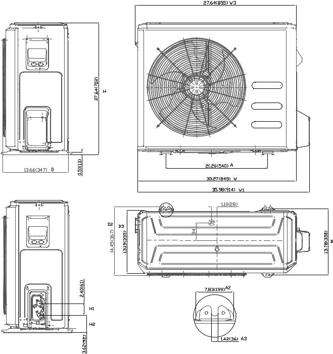
DIMENSIONS
Table 8—Dimensions
|
System Size |
Height (H) in. (mm) |
Width (W) in. (mm) |
Depth (D) in. (mm) |
Weight-Net lbs. (kg) |
||
|
12K |
(115V) |
21.85(555) |
30.31(770) |
11.81(300) |
57.8(26.2) |
|
Cooling |
12K |
(208/230V) |
21.85(555) |
30.31(770) |
11.81(300) |
53.8(24.4) |
|
Only |
|||||||
|
|
|
|
|
|
||
|
18K |
(208/230V) |
21.85 (555) |
30.31 (770) |
11.81 (300) |
65.9 (29.9) |
|
|
24K |
(208/230V) |
27.64(702) |
33.27(845) |
14.29(363) |
88.6(40.2) |
|
|
System Size |
Height (H) in. (mm) |
Width (W) in. (mm) |
Depth (D) in. (mm) |
Weight-Net lbs. (kg) |
||
|
12K |
(115V) |
21.85(555) |
30.31(770) |
11.81(300) |
69(31.3) |
|
Heat |
9K |
(208/230V) |
21.85(555) |
30.31(770) |
11.81(300) |
63(28.6) |
|
|
|
|
|
|
|
||
Pump |
12K |
(208/230V) |
21.85(555) |
30.31(770) |
11.81(300) |
65.5(29.7) |
|
|
18K |
(208/230V) |
21.81(554) |
31.50(800) |
13.11(333) |
79.6(36.1) |
|
|
24K |
(208/230V) |
27.64(702) |
33.27(845) |
14.29(363) |
114.2(51.8) |
|
30.66(779) W3
21.85(555) |
H |
|
|
0.47(12) |
|
11.81(300) D |
|
D2 13.07(322)
2.36(60)  H1
H1

 H2 3.66(93)
|
|
19.17(487) |
W1 |
|
|
|
|
30.31(770) W |
|
||
|
B2 |
0.98(25) |
|
2.76(70) W |
|
|
3.54(90) |
B1 |
|
||
D3 |
|
|
11.73(298) |
|
|
11.26(286) |
|
|
D1 |
||
|
|
|
|
|
|
|
2.42(61.5) |
A2 |
|
|
|
|
|
|
Unit: inch(mm) |
|
.24(6) |
0.47(12) |
A1 |
|
0 |
||||
R |
|
|
|
|
Fig. 1 – Sizes 9K and 12K Heat Pump and Size 18K Cooling Only
5

DIMENSIONS − OUTDOOR (CONT)
|
(554) |
H |
|
21.81 |
|
|
0.47 (1 2) |
|
13.11 |
(333) |
|
D |
|
|
|
|
|
|
|
|
|
|
|
|
|
|
(325) |
|
D2 |
|
|
|
|
|
|
|
|
|
|
|
|
|
||
|
|
|
|
|
|
|
|
|
|
|
|
|
||
|
|
|
|
|
|
|
|
|
|
|
|
|
||
|
|
|
|
|
|
|
|
|
|
|
|
|
||
|
|
|
|
|
|
|
|
|
|
|
|
|
||
|
|
|
|
|
|
|
|
|
|
|
|
|
||
|
|
|
|
|
|
|
|
|
|
|
|
12.80 |
|
|
|
|
|
|
|
|
|
|
|
|
|
(6 0) |
|
|
|
|
|
|
|
|
|
|
|
|
|
|
H1 |
|
|
|
|
|
|
|
|
|
|
|
|
2.36 |
|
|
|||
|
|
|
|
|
|
|
|
|
|
|
|
|||
|
|
|
|
|
|
|
|
|
|
|
|
|
|
|
|
|
|
|
|
|
|
|
|
|
|
|
|
|
|
|
|
|
|
|
|
|
|
|
|
|
|
|
|
|
12.24 (311)
D3
20.24 (514) |
W1 |
|
31.50 |
(800) |
2.76 (7 0) |
W |
|
W2 |
(1 06) |
B2 |
2.43 (6 1.8) |
4.17 |
|
B1 |
(340) |
D1 |
|
13.39 |
||
|
3.37 (8 5.5)
R |
|
|
0 |
|
|
. |
|
|
7 |
|
|
9 |
|
|
|
(R |
|
|
2 |
|
|
0 |
|
|
|
) |
H2
0.87 (2 2) |
|
|
|
) |
|
|
|
|
|
|
|
|
6 |
|
A1 |
|
.24 |
(R |
|
|
0 |
|
|
|
|
R |
|
|
|
2.43 (6 1.6) |
|
|
|
Unit: inch(mm) |
A2 |
|
|
|
|
Fig. 2 – Size 18K Heat Pump
6
DIMENSIONS − OUTDOOR (CONT)
Unit: inch (mm)
Fig. 3 – Size 24K
7
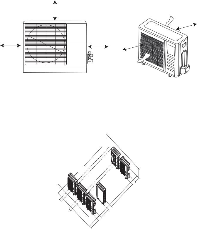
CLEARANCES
A
Air-inlet
E
D |
B |
C |
|
Air-outlet
Fig. 4 – Outdoor Unit Clearance
Table 9—Clearances
UNIT |
MINIMUM VALUE in. (mm) |
A |
24 (610) |
B |
24 (610) |
C |
24 (610) |
D |
4 (101) |
E |
4 (101) |
NOTE: The outdoor unit must be mounted at least 2in. (50mm) above the maximum anticipated snow depth.
9.8in (25cm) or more for proper airflow 24in (61cm) or more is recommended for service
9.8in (25cm) or more for proper airflow 24in (61cm) or more is recommended for service
19in (48cm) or more on a multiple parallel unit arrangement 4in (10cm) or more on a single parallel unit arrangement
118in (300cm) or more
59in (150cm) |
24in (60cm) |
or more on a |
or more |
multiple parallel |
|
unit arrangement |
|
24in (61cm) or more |
|
on a single parallel |
|
unit arrangement |
|
Fig. 5 – Clearances for Multiple Units
8

ELECTRICAL DATA
Table 10—Electrical Data (Cooling Only)
|
Outdoor Unit Size |
12K |
12K |
18K |
24K |
|
Cooling Only |
Volts-PH-Hz |
(115V) |
(208/230V) |
(208/230V) |
(208/230V) |
|
|
|
|
|
|
||
|
Max – Min* |
127-104 |
253-187 |
253-187 |
253-187 |
|
|
Oper. Voltage |
|||||
|
|
|
|
|
||
Power Supply |
MCA |
13 |
11 |
15 |
18 |
|
MOCP |
20 |
15 |
20 |
25 |
||
|
||||||
Compressor |
RLA |
9.5 |
6.8 |
9 |
12 |
|
|
FLA |
0.6 |
0.5 |
0.6 |
0.6 |
|
Outdoor Fan Motor |
Rated HP |
0.054 |
0.054 |
0.054 |
0.068 |
|
|
Output |
40 |
40 |
40 |
50 |
Table 11—Electrical Data (Heat Pump)
|
Outdoor Unit Size |
12K |
9K |
12K |
18K |
24K |
|
Heat Pump |
Volts-PH-Hz |
(115V) |
(208/230V) |
(208/230V) |
(208/230V) |
(208/230V) |
|
|
|
|
|
|
|
||
|
Max – Min* |
127-104 |
253-187 |
253-187 |
253-187 |
253-187 |
|
|
Oper. Voltage |
||||||
|
|
|
|
|
|
||
Power Supply |
MCA |
13 |
8 |
10 |
15 |
18 |
|
MOCP |
20 |
15 |
15 |
20 |
25 |
||
|
|||||||
Compressor |
RLA |
10.5 |
5.5 |
6.8 |
10.5 |
12 |
|
|
FLA |
0.6 |
0.4 |
0.4 |
0.5 |
0.6 |
|
Outdoor Fan Motor |
Rated HP |
0.054 |
0.054 |
0.054 |
0.054 |
0.068 |
|
|
Output |
40 |
40 |
40 |
40 |
50 |
*Permissible limits of the voltage range at which the unit will operate satisfactorily.
LEGEND
FLA - Full Load Amps
MCA - Minimum Circuit Amps
MOCP - Maximum Over-Current Protection
RLA - Rated Load Amps
WIRING
All wires must be sized per NEC (National Electrical Code) or CEC (Canadian Electrical Code) and local codes. Use Electrical Data table MCA (minimum circuit amps) and MOCP (maximum over current protection) to correctly size the wires and the disconnect fuse or breakers respectively.
Recommended Connection Method for Power and Communication Wiring:
The main power is supplied to the outdoor unit. The field supplied 14/3 stranded wire with ground with a 600 volt insulation rating, power/communication wiring from the outdoor unit to indoor unit consists of four (4) wires and provides the power for the indoor unit. Two wires are line voltage AC power, one is communication wiring (S) and the other is a ground wire. Wiring between indoor and outdoor unit is polarity sensitive. The use of BX wire is NOT recommended.
If installed in a high Electromagnetic field (EMF) area and communication issues exists, a 14/2 stranded shielded wire can be used to replace L2/N and (S) between outdoor unit and indoor unit landing the shield onto ground in the outdoor unit only.
!CAUTION
EQUIPMENT DAMAGE HAZARD
Failure to follow this caution may result in equipment damage or improper operation.
Wires should be sized based on NEC and local codes.
!CAUTION
EQUIPMENT DAMAGE HAZARD
Failure to follow this caution may result in equipment damage or improper operation.
SBe sure to comply with local codes while running wire from the indoor unit to the outdoor unit.
SEvery wire must be connected firmly. Loose wiring may cause the terminal to overheat or result in unit malfunction. A fire hazard may also exist. Ensure all wiring is tightly connected.
SNo wire should touch the refrigerant tubing, compressor or any moving parts.
SDisconnecting means must be provided and shall be located within sight and readily accessible from the air conditioner.
SConnecting cable with conduit shall be routed through the hole in the conduit panel.
9
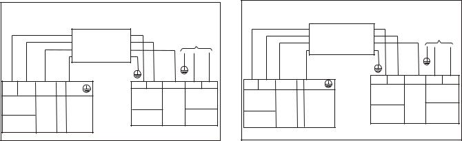
CONNECTION DIAGRAMS
|
|
|
|
|
|
115-1-60 |
|
|
|
|
|
CONNECTING CABLE |
|
|
FIELD POWER SUPPLY |
||
|
|
|
|
|
|
|
|
|
|
|
|
OUTDOOR TO INDOOR |
|
|
|
|
|
|
|
|
|
L |
N |
GND |
N |
|
L |
N |
S |
GND |
S |
L |
|||
Power to |
Indoor |
Main |
|
|||||
Indoor Unit |
Indoor |
|
|
|||||
Ground |
Indoor Unit Signal |
Power Supply |
||||||
Power Supply Signal |
115-1-60 |
High |
115-1-60 |
|||||
115-1-60 |
High |
|
Voltage |
|||||
Voltage |
|
|
|
|
|
|
||
|
|
|
|
|
|
208/230-1-60 |
|
|
|
|
|
CONNECTING CABLE |
|
|
FIELD POWER SUPPLY |
||
|
|
|
OUTDOOR TO INDOOR |
|
|
|
|
|
|
|
|
|
|
|
|
GND |
|
L1 |
L2 |
S |
GND |
L1 |
L2 |
S |
L1 |
L2 |
Power |
to |
Indoor |
Main |
|
||||
|
|
|
|
|||||
Indoor Unit |
Indoor |
Ground |
Indoor Unit Signal |
Power Supply |
||||
Power Supply Signal |
|
|
High |
|
|
|||
|
|
High |
|
|
|
|
|
|
|
|
|
208/230-1-60 Voltage 208/230-1-60 |
|||||
208/230-1-60 Voltage |
|
|||||||
|
|
|
|
|
|
|||
115V Indoor Unit |
115V Outdoor Unit |
230V Indoor Unit |
230V Outdoor Unit |
Fig. 6 – Connection Diagrams
Notes:
1.Do not use thermostat wire for any connection between indoor and outdoor units.
2.All connections between indoor and outdoor units must be as shown. The connections are sensitive to polarity and will result in a fault code.
10
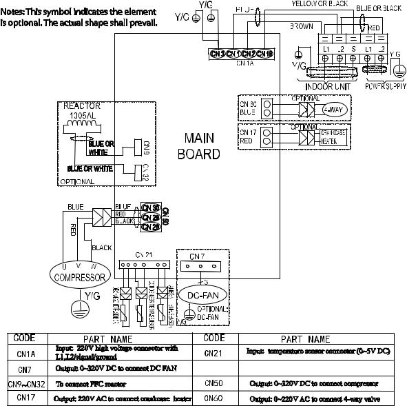
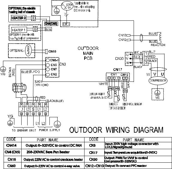
WIRING DIAGRAMS (COOLING ONLY)
Fig. 7 – Wiring Diagram Size − Cooling Only Size 12K (115V)
11
WIRING DIAGRAMS (COOLING ONLY (CONTINUED))
Fig. 8 – Wiring Diagram Cooling Only Size 12K (230V)
12

WIRING DIAGRAMS (COOLING ONLY (CONTINUED))
Fig. 9 – Wiring Diagram Cooling Only Sizes 18−24K
13

WIRING DIAGRAMS (HEAT PUMP)
Fig. 10 – Wiring Diagram Heat Pump Size 12K (115V)
14

WIRING DIAGRAMS (HEAT PUMP (CONTINUED))
Fig. 11 – Wiring Diagram Heat Pump Sizes 09, 12, 18 (230V)
15
WIRING DIAGRAMS (HEAT PUMP (CONTINUED))
Fig. 12 – Wiring Diagram Heat Pump Size 24 (230V)
16

REFRIGERATION CYCLE DIAGRAMS
INDOOR |
|
OUTDOOR |
|
LIQUID SIDE |
CHECK VALVE |
|
(Heating Model only) |
|
|
|
|
|
2−WAY VALVE |
|
|
|
CAPILIARY TUBE |
HEAT |
|
HEAT |
EXCHANGE |
|
EXCHANGE |
(EVAPORATOR) |
T1 Room temp. |
(CONDENSER) |
|
|
|
|
sensor |
|
T2 Evaporator 
temp. sensor
GAS SIDE 


 4−WAY VALVE
3−WAY VALVE
ACCUMULATOR
 COOLING
COMPRESSOR


 HEATING
Fig. 13 – Heat Pumps
17

REFRIGERANT LINES
General Refrigerant Line Sizing
1The outdoor units are shipped with a full charge of R410A refrigerant. All charges, line sizing, and capacities are based on runs of 25ft. (7.6 m). For runs over 25 ft. (7.6 m), consult the long−line applications section for the proper charge adjustments.
2The minimum refrigerant line length between the indoor and outdoor units is 10 ft. (3 m).
3Refrigerant lines should not be buried in the ground. If it is necessary to bury the lines, not more than 36 in (914 mm) should be buried. Provide a minimum 6in (152 mm) vertical rise to the service valves to prevent refrigerant migration.
Table 12 lists the maximum lengths allowed.
4 Both lines must be insulated. Use a minimum of 1/2in. (12.7 mm) thick insulation. Closed−cell insulation is recommended in all long−line applications.
5 Special consideration should be given to isolating interconnecting tubing from the building structure. Isolate the the tubing so vibration or noise is not transmitted into the structure.
IMPORTANT: Both refrigerant lines must be insulated separately.
Table 12—Piping and Refrigerant Information
|
System Size |
|
12K (115V) |
9K (208-230V) |
12K (208-230V) |
18K (208-230V) |
24K (208-230V) |
|
Min. Piping Length |
ft. (m) |
10(3) |
10(3) |
10(3) |
10(3) |
10(3) |
|
Standard Piping Length |
ft. (m) |
25(7.5) |
25(7.5) |
25(7.5) |
25(7.5) |
25(7.5) |
|
Max. outdoor-indoor |
|
|
|
|
|
|
|
height difference |
ft. (m) |
33(10) |
33(10) |
33(10) |
66(20) |
66(20) |
|
(OU higher than IU) |
|
|
|
|
|
|
|
Max. outdoor-indoor |
|
|
|
|
|
|
|
height difference |
ft. (m) |
33(10) |
33(10) |
33(10) |
66(20) |
66(20) |
|
(IU higher than OU) |
|
|
|
|
|
|
|
Max. Piping Length with |
|
|
|
|
|
|
|
no additional refrigerant |
ft. (m) |
25(7.5) |
25(7.5) |
25(7.5) |
25(7.5) |
25(7.5) |
|
charge per System |
||||||
|
|
|
|
|
|
|
|
Piping |
(Standard Piping length) |
|
|
|
|
|
|
|
Total Max. Piping |
ft. (m) |
82(25) |
82(25) |
82(25) |
98(30) |
164(50) |
|
Length per system |
||||||
|
|
|
|
|
|
|
|
|
Additional refrigerant |
|
|
|
|
|
|
|
charge (between Standard |
Oz/ft (g/m) |
0.161(15) |
0.161(15) |
0.161(15) |
0.161(15) |
0.322(30) |
|
– Max piping length) |
|
|
|
|
|
|
|
Suction Pipe |
In (mm) |
1/2(12.7) |
3/8(9.52) |
1/2(12.7) |
1/2(12.7) |
5/8(15.9) |
|
(size - connection type) |
||||||
|
|
|
|
|
|
|
|
|
Liquid Pipe |
In (mm) |
1/4(6.35) |
1/4(6.35) |
1/4(6.35) |
1/4(6.35) |
3/8(9.52) |
|
(size - connection type) |
||||||
|
|
|
|
|
|
|
|
|
Refrigerant Type |
Type |
R410A |
R410A |
R410A |
R410A |
R410A |
|
Cooling Only Models |
Lbs (kg) |
1.30(0.59) |
N/A |
1.17 (0.53) |
1.98 (0.9) |
2.56 (1.16) |
|
Charge Amount |
||||||
Refrigerant |
|
|
|
|
|
|
|
Heat Pump Models |
|
|
|
|
|
|
|
|
Lbs (kg) |
2.12(0.96) |
1.76(0.8) |
2.12(0.96) |
2.82 (1.28) |
3.97 (1.8) |
|
|
Charge Amount |
||||||
|
|
|
|
|
|
|
Long Line Applications,:
1No change in line sizing is required.
2Add refrigerant per Table 12.
18
SYSTEM EVACUATION AND CHARGING
!CAUTION
UNIT DAMAGE HAZARD
Failure to follow this caution may result in equipment damage or improper operation.
Never use the system compressor as a vacuum pump.
Refrigerant tubes and indoor coil should be evacuated using the recommended deep vacuum method of 500 microns. Always break a vacuum with dry nitrogen.
System Vacuum and Charge
Using Vacuum Pump
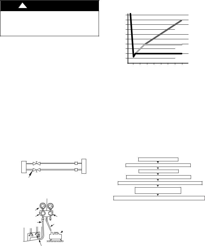
1Completely tighten all flare nuts and connect manifold gage charge hose to a charge port of the low side service valve (see Fig. 14).
2Connect the charge hose to the vacuum pump.
3Fully open the low side of manifold gage (see Fig. 15).
4Start the vacuum pump
5Evacuate using the triple evacuation method.
6After evacuation is complete, fully close the low side of manifold gage and stop the vacuum pump operation.
7The factory charge contained in the outdoor unit is good for up to 25 ft. (8 m) of line length. For refrigerant lines longer than 25 ft. (8 m), add refrigerant as specified in the
ADDITIONAL REFRIGERANT CHARGE table in this document.
8Disconnect the charge hose from the charge connection of the low side service valve.
9Fully open service valves B and A.
10Securely tighten the service valves caps.
Outdoor Unit |
Refrigerant |
Indoor Unit |
A |
Low Side |
C |
B |
High Side |
D |
|
||
Service Valve |
|
|
Fig. 14 – Service Valve |
|
|
Manifold Gage |
|
|
500 microns |
|
|
Low side valve |
High side valve |
|
Charge hose |
Charge hose |
|
|
|
|
 Vacuum pump
Low side valve
Fig. 15 – Manifold
Deep Vacuum Method
The deep vacuum method requires a vacuum pump capable of pulling a vacuum of 500 microns and a vacuum gage capable of accurately measuring this vacuum depth. The deep vacuum method is the most positive way of assuring a system is free of air and liquid water (see Fig. 16).
5000 |
|
|
|
|
|
|
|
4500 |
|
|
|
|
|
|
|
4000 |
|
|
|
|
|
LEAK IN |
|
3500 |
|
|
|
|
|
||
|
|
|
|
|
SYSTEM |
||
3000 |
|
|
|
|
|
||
|
|
|
|
|
|
|
|
2500 |
|
|
|
|
|
|
|
MICRONS2000 |
|
|
|
|
|
VACUUM TIGHT |
|
1500 |
|
|
|
|
|
||
|
|
|
|
|
TOO WET |
||
1000 |
|
|
|
|
|
||
|
|
|
|
|
TIGHT |
||
500 |
|
|
|
|
|
||
|
|
|
|
|
DRY SYSTEM |
||
|
|
|
|
|
|
||
0 |
1 |
2 |
3 |
4 |
5 |
6 |
7 |
|
|
|
MINUTES |
|
|
|
|
Fig. 16 – Deep Vacuum Graph
Triple Evacuation Method
The triple evacuation method should be used. Refer to Fig. 17 and proceed as follows:
1Pump the system down to 1500 microns and allow the pump to continue operating for an additional 15 minutes.
2Close the service valves and shut off the vacuum pump.
3Connect a dry nitrogen cylinder and regulator to the system and break vacuum until the system reaches 2 psig.
4Close the service valve and allow the system to stand for 1hr. During this time, the dry nitrogen can diffuse throughout the system absorbing moisture.
5Pump the system down to 1000 microns.
6Break the vacuum with dry nitrogen (2 psig).
7Pump the system down to 500 microns.
8Perform the hold test for 30 minutes.
EVACUATE TO 1500 MICRONS
BREAK VACUUM WITH DRY NITROGEN TO 2 PSIG
EVACUATE TO 1000 MICRONS
BREAK VACUUM WITH DRY NITROGEN TO 2 PSIG
EVACUATE TO 500 MICRONS MINIMUM (HOLD FOR 30 MINUTES)
CHECK FOR TIGHT, DRY SYSTEM (IF IT HOLDS DEEP VACUUM)
RELEASE CHARGE INTO SYSTEM BY OPENING VALVES COMPLETELY
Fig. 17 – Triple Evacuation Method
Final Tubing Check
IMPORTANT: Check to be certain factory tubing on both indoor and outdoor unit has not shifted during shipment. Ensure tubes are not rubbing against each other or any sheet metal. Pay close attention to feeder tubes, making sure wire ties on feeder tubes are secure and tight.
19

Operation Modes and Functions
FAN Mode
1Outdoor fan and compressor stop
2Temperature setting function is disabled, and no setting temperature is displayed.
3Indoor fan can be set to high/med/low/auto
4The louver operates the same in the COOLING mode.
5Auto fan
Fig. 18 – Auto Fan
COOLING Mode
Compressor Running Rules:
SWhen T1*Ts < 28.4_F(*2_C), the compressor stops.
SWhen T1*TS > 31.1_F(*0.5_C), the compressor activates.
SWhen the AC runs in the mute mode, the compressor runs with low frequency.
SWhen the current is more than setting value, the current protection function activates, and the compressor stops.
Outdoor Fan Running Rules:
The outdoor unit runs at a different fan speed according to T4. For different outdoor units, the fan speeds differ.
Fig. 19 – Outdoor Fan Running Rules
The auto fan adheres to the following rules.
Fig. 20 – Auto Fan
Fig. 21 – Compressor Temperature Protection
When the condenser temperature temperature is higher than the setting value, the compressor stops.
Compressor Running Rules
When T1−Ts>− T, the compressor stops, when T1−TS< T−1.5 the compressor will be on. T is the
programmed parameter of temperature compensation. When the AC run in mute mode, the compressor runs with low frequency.
When the current is more than setting value, the current protection function is activated and the compressor stops.
Outdoor Fan Running Rules
The outdoor unit runs at different fan speed according to T4. For different outdoor units, the fan speeds are different.
Fig. 22 – Outdoor Fan Running Rules
20
Auto Fan Action in HEATING Mode
T1
a
b
c  d
d  e
e
Fig. 23 – Auto Fan Action in HEATING Mode DEFROST Mode
The air conditioner enters the DEFROST mode according to the T3 temperature value and the T3 temperature change value range plus the compressor running time.
During the DEFROST mode, the compressor continues to runs, the indoor and outdoor motors stop, and the indoor unit defrost
lamp illuminates and  appears.
If any one of the following items is satisfied, the defrosting finishes and the machine reverts to the normal heating mode.
−−−−T3 rises to be higher than TCDE1_C.
−−−−T3 keeps to be higher than TCDE2_C for 80 seconds.
−−−−The machine has run for 15 minutes in defrosting mode.
Evaporator Coil Temperature Protection
T2
Off
TEstop
Decrease
TEdown
Hold
TEH2
Resume
Fig. 24 – Evaporator Coil Temperature Protection
NOTE: The following applies to Fig. 24:
SOff: Compressor stops
SDecrease: Decrease the running frequency to the lower level
SHold: Keep the current frequency
SResume: No limitation for frequency
When the evaporator temperature is higher than the setting protection value, the compressor stops.
Auto−Mode
This mode can be chosen with the remote controller and the setting temperature can be changed between 62.6_F(17_C)~86_F(30_C).
In the AUTO mode, the machine chooses the COOLING, HEATING or FAN−ONLY mode according to T ( T =T1−Ts).
Table 13—Auto Mode
ΔT=T1-Ts |
Running mode |
ΔT 2_C |
Cooling |
-2≤ΔT≤2_C |
Fan-only |
ΔT<-2_C |
Heating |
The indoor fan runs under auto fan in the relevant mode. The louver operates the same in the relevant mode. If the machine switches modes between HEATING and COOLING, the compressor stops for 15 minutes and then chooses the mode according to T1−Ts. If the setting temperature is modified, the machine chooses the running function again.
DRY mode
Indoor fan speed is fixed at breeze and can not be changed.
The louver angle is the same as in the cooling mode.
Low indoor room temperature protection
In the DRYING mode, if the room temperature is lower than 50_F (10_C), the compressor stops and does not resume until the room temperature exceeds 53.6_F (12_C).
Evaporator anti*freezing protection, condenser high temperature protection and outdoor unit frequency limit are active and are the same as that in the cooling mode. The outdoor fan operates the same as in cooling mode.
Forced Operation Function
SEnter forced operation function: When the machine is off, press Touch to engage the the Forced Auto Mode. Press Touch again, within 5 seconds, to engage the
Forced Cooling Mode. In Forced Auto, forced cooling or any other operation mode, press the touch button to turn off the unit. In the forced operation mode, all general protections and remote control are available.
Operation rules:
SForced Cooling Mode: The compressor runs at the F2 frequency and the indoor fan runs as a breeze. After running for 30 minutes, the unit enters the auto mode as 75.2_F (24_C) setting temperature.
SForced Auto Mode: The forced auto mode is the same as the normal auto mode with a 75.2_F (24_C) setting temperature.
AUTO−RESTART Function
The indoor unit is equipped with the AUTO−RESTART function, which is carried out through an auto−restart module. In the event of a sudden power failure, the module memorizes the setting conditions prior to the power failure. The unit resumes the previous operation setting (not including the SWING function) automatically three (3) minutes after the power returns.
If the memorization condition is the FORCED COOLING mode, the unit will run in the COOLING mode for 30 minutes and turn to the AUTO mode at the 75.2_F(24_C) setting temperature.
If the air conditioner is off before the power turns off and the air conditioner is required to start up, the compressor delays start up for 1 minute before powering on. In other instances, the compressor waits three (3) minutes before restarts.
Refrigerant Leak Detection
With this new technology, the display area displays “EC” when the outdoor unit detects a refrigerant leak. This function is only active in cooling mode. It can better prevent the compressor being damaged by refrigerant leakage or compressor overload.
Open Condition: When the compressor is active, the value of the Coil temperature of evaporator T2 has no change or very little change.
46_F (8_C) Heating
When the compressor is running, the indoor fan motor runs without the ANTI−COLD air function. When the compressor is off, the indoor fan motor is off.
21

Point Check Function
Press the remote controller’s LED DISPLAY or LED or MUTE button three times, and then press the AIR DIRECTION or SWING button three times in ten seconds, the buzzer rings for two seconds. The air conditioner enters into the information enquiry status.
Press the LED DISPLAY or AIR DIRECTION button to check the next or front item’s information.
When the air conditioner enters the information enquiry status, it displays the code name in 2 seconds (see Table 14).
Table 14—Information Enquiry
ENQUIRY INFORMATION |
DISPLAYING CODE |
MEANING |
T1 |
T1 |
T1 temp. |
T2 |
T2 |
T2 temp. |
T3 |
T3 |
T3 temp. |
T4 |
T4 |
T4 temp. |
T2B |
Tb |
T2B temp. |
TP |
TP |
TP temp. |
TH |
TH |
TH temp. |
Targeted Frequency |
FT |
Targeted Frequency |
Actual Frequency |
Fr |
Actual Frequency |
Indoor Fan Speed |
IF |
Indoor fan speed |
Outdoor Fan Speed |
OF |
Outdoor fan speed |
EXV Opening Angle |
LA |
EXV opening angle |
Compressor continuous running time |
CT |
Compressor continuous running time |
Compressor stop causes |
ST |
Compressor stop causes |
Reserve |
A0 |
|
Reserve |
A1 |
|
Reserve |
b0 |
|
Reserve |
b1 |
|
Reserve |
b2 |
|
Reserve |
b3 |
|
Reserve |
b4 |
|
Reserve |
b5 |
|
Reserve |
b6 |
|
Reserve |
dL |
|
Reserve |
Ac |
|
Reserve |
Uo |
|
Reserve |
Td |
|
When the air conditioner enters the information enquiry status, it displays the code value for 25 seconds (see Table 15).
Table 15—Information Enquiry
ENQUIRY |
DISPLAY VALUE |
MEANING |
REMARK |
|
INFORMATION |
||||
|
|
|
||
|
-1F,-1E,-1d,-1c, |
-25,-24,-23,-22,-21,-20 |
|
|
|
-1b,-1A |
|
||
|
|
1. The displaying temperature is the actual value. |
||
|
|
|
||
|
-19—99 |
-19—99 |
_ |
|
T1,T2,T3,T4, |
|
|
2. The temperature is C no matter what kind of remote |
|
A0,A1,…A9 |
100,101,…109 |
controller is used. |
||
T2B,TP,TH, |
||||
Targeted |
b0,b1,…b9 |
110,111,…119 |
3. T1,T2,T3,T4,T2B display range:-25~70, TP display |
|
Frequency, |
range:-20~130. |
|||
c0,c1,…c9 |
120,121,…129 |
|||
Actual |
4. Frequency display range: 0~159HZ. |
|||
|
|
|||
Frequency |
d0,d1,…d9 |
130,131,…139 |
5. If the actual value exceeds the range, it displays the |
|
|
|
|
||
|
E0,E1,…E9 |
140,141,…149 |
maximum value or minimum value. |
|
|
F0,F1,…F9 |
150,151,…159 |
|
|
|
0 |
OFF |
|
|
|
1,2,3,4 |
Low speed, Medium speed, High |
For some big capacity motors. |
|
Indoor fan speed |
speed, Turbo |
|||
|
|
|||
/Outdoor fan speed |
|
Actual fan speed = Display value |
For some small capacity motors, the display value is from 14-FF |
|
|
|
|||
|
14-FF |
turns to decimal value and then |
(hexadecimal), the corresponding fan speed range |
|
|
|
multiply 10. The unit is RPM. |
is from 200-2550 RPM. |
|
|
|
Actual EXV opening value = |
|
|
EXV opening angle |
0-FF |
Display value turns to decimal |
|
|
|
|
value and then multiply 2. |
|
|
Compressor |
|
|
If the actual value exceeds the range, it displays the |
|
continuous running |
0-FF |
0-255 minutes |
||
maximum value or minimum value. |
||||
time |
|
|
||
|
|
|
||
Compressor stop |
0-99 |
For the detailed meaning, please |
Decimal display |
|
causes |
consult with engineer |
|||
|
|
|||
Reserve |
0-FF |
|
|
22

TROUBLESHOOTING
Safety
Electricity power is kept in capacitors even if the power supply is shut off.
NOTE: Remember to discharge the electricity power in capacitor.
Electrolytic Capacitors
(HIGH VOLTAGE! CAUTION!)
Fig. 25 – Electrolytic Capacitors
For other models, please connect discharge resistance (approximately 100Ω 40W) or a soldering iron (plug) between the +, − terminals of the electrolytic capacitor on the contrary side of the outdoor PCB.
Fig. 26 – Discharge Position
NOTE: Fig. 26 is for reference only. The plug on your unit may differ.
23
Loading...