


38VTA060
CARRIER 38VTA060, 38VTA050, 38VTA040, 42XQA060, 42XQA050 User Manual [ru]
...
OWNER’S MANUAL
42XQ/XQA
®
UNDERCEILING
CONSOLE
42XQ 42XQA
42XQ : Cooling only direct expansion Fan Coil Unit (Wireless Control)
42XQA : Cooling only direct expansion Fan Coil Unit (Wired Control)

Thank you for choosing Carrier!
You can be sure that you’ve made a wise choice, because the same
pride we take in manufacturing the Carrier equipment installed in the
Astrodome in Texas, in the Sistine Chapel, in the Capitol – the seat of
the US Congress – and in thousands of other installations worldwide,
is embodied in the design of the unit you have just purchased.
One of the greatest benefits to await you when using your air conditioner
is that, in addition to maintaining a pleasant temperature in the area
where it is installed, the ambient air is also filtered and dehumidified,
thus improving the quality of the air you breathe.
This manual has been created to familiarize you with all of the
technological features and benefits which this air conditioner unit can
offer.
This manual also contains important information regarding the
maintenance of your new air conditioner, servicing the unit and, above
all, running it in an economical way . Set aside a few minutes to carefully
read through the contents of this manual and learn to optimize the use
of your new Carrier device in terms of personal comfort and economy
of operation.

CONTENTS
PRECAUTIONS.................................................................................................. 3
Safety considerations 3
DISPLAYS OF THE INDOOR UNIT, LED INDICATORS & CONTROLS............ 6
Error codes 6
Emergency operation 7
REMOTE CONTROL.......................................................................................... 8
Using the selected functions 10
Using the wireless remote control 11
Using the wired remote control 17
Setting the operating mode 19
INFORMATION ABOUT FILTERS.................................................................... 21
CARE AND MAINTENANCE............................................................................ 22
Operating conditions 22
Operation during power outages 22
PRACTICAL TIPS............................................................................................. 23
Cleaning the Indoor Unit 24
Cleaning the Outdoor Unit 24
Cleaning the filters 25
PRECAUTIONS
Safety considerations
The installation, servicing and maintenance
of air conditioning equipment may be
hazardous due to the pressure which the
refrigerant gas exerts on the interior, and
its electrical components. Only specialized
and professionally qualified personnel may
install, repair or perform servicing work on
air conditioning equipment. Non-specialized
people may only perform basic
maintenance work such as: cleaning the
coils and cleaning and/or replacing the
filters.
All other types of maintenance work may
only be performed by specialized
personnel. To perform such work, the
installer must follow the safety standards
applicable, and must wear safety goggles,
clothing and gloves suitable for this
purpose. Appropriate protection must be
used during welding work; a fire
extinguisher must always be kept close to
hand.
For your safety, read these instructions
through carefully and respect all of the
labels marked WARNING below.
WARNING
WARNING or CAUTION contained in this
manual or attached to the housing of the
unit.
Consult your local regulations applicable
with respect to electrical installations for
special requirements.
Recognize the safety information
The symbol “ ” indicates a safety alert.
When you see this symbol, it is because
there is a potential risk of material damage
or personal injury . Understand the meaning
of the words DANGER, WARNING AND
CAUTION. These words are used in
conjunction with the alert symbol.
DANGER means situations with a severe
risk to injury to people, including the risk of
death. The word WARNING means
situations which could result in personal
injury, including death. The word CAUTION
indicates unsafe practices which could
result in minor personal injury or material
damage.
• Do not attempt to interconnect units
from different manufacturers without
first consulting your Carrier
representative or an engineer
specializing in air conditioning. The
incompatibility between the indoor
and outdoor unit and its control
devices could cause serious problems
for both units and invalidate the
manufacturers’ warranty coverage.
Carrier accepts no liability and will
cancel the product warranty if these
installation instructions are not
followed as indicated, or if the wiring
is changed. Consult your preferred
Carrier representative for further
details.
3
• Before installing, modifying or performing
servicing work on the system, check
that the electrical power supply to the
unit has been switched off. Check that
there is not more than one power
switch. Check and label each switch
present with the appropriate wording.
Electric shocks can cause personal
injury, and even death. If the power
supply cable is damaged, it must be
replaced only with an authorized
Carrier spare part by its network of
authorized dealers.
CAUTION
DISCONNECTING THE UNIT FROM
THE MAIN POWER SUPPLY
These units must be connected to the
main electrical power supply through a
circuit-breaker or switch fuse with an
appropriate capacity and with a minimum
separation between the contacts of 3mm.
If this is not possible, a contact/container
combination equipped with an active
earth wire must be used. The contact
must have easy access after installation.
The contact must be disconnected from
the receptacle to ensure that no electrical
power gets to the unit. It is vitally
important to follow the safety standards
in force at the connection location and
also to check that the electrical power
supply is actively equipped with an earth
cable.
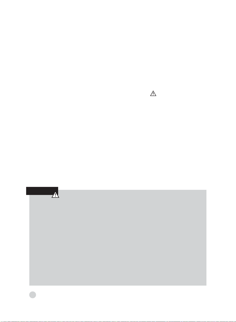
1) Do not spray flammable aerosols near
to the unit. The unit may be damaged if it
comes into contact with gasoline, solvents,
benzene, insecticides or other chemical
substances.
2) T o prevent electric shocks, never splash
water into either the indoor or outdoor
units.
WARNING
Do not attempt to disconnect the unit
at the main power switch. Always use
the unit’s control when you want to
disconnect the system.
3) Do not insert your hands or fingers, or place
objects inside the air discharge grille of the
outdoor unit, because the fan rotates at
very high speeds, which may cause
serious personal injury.
4
4) Use only a circuit-breaker with a suitable
capacity.
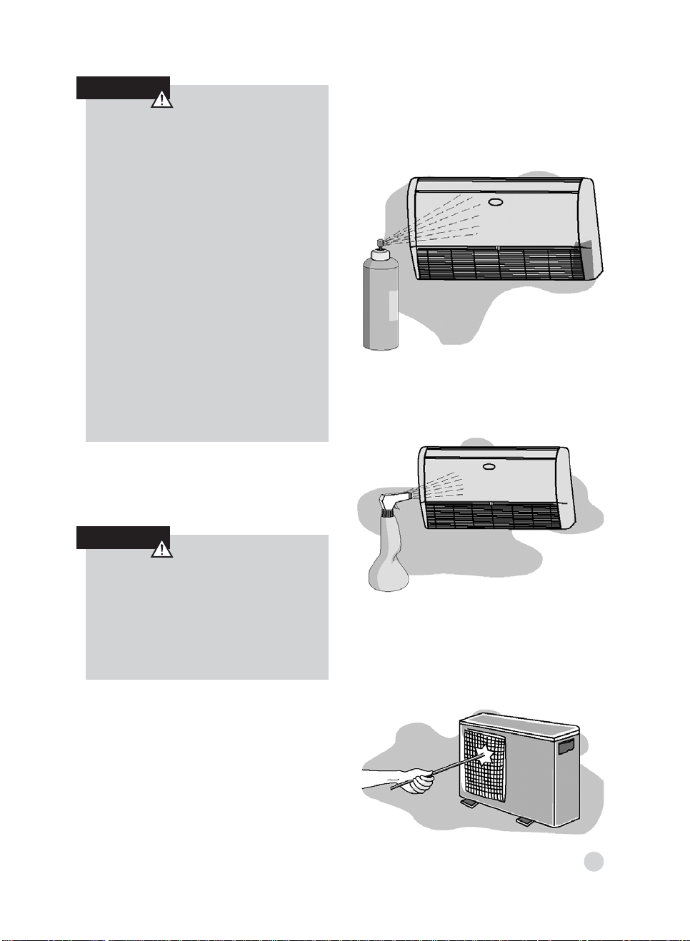
Keep the unit away from heat sources.
High temperatures may cause physical
damage to the unit.
5) Do not obstruct the air discharge of any
of the indoor and outdoor unit. Doing
so, blocks the airflow, reducing the
cooling capacity and causing the unit
to malfunction.
6) The manufacturer accepts no liability in the
event of damage caused by: mistakes
or changes when establishing the
electrical connections or refrigerant gas
connections, during installation or due to
the inappropriate use of the equipment.
Failure to observe these instructions will
immediately invalidate the warranty of
your unit.
This unit will only operate correctly if it is
installed and tested by personnel
professionally qualified and trained for
such work.
7) In summer, prevent sunlight from entering
the air-conditioned area as far as
possible. You can do this by using
curtains or blinds on the windows.
8) Use the voltage indicated on the unit’s
data plate. Using a voltage different from
the specified voltage may cause very
serious damage to the unit.
5
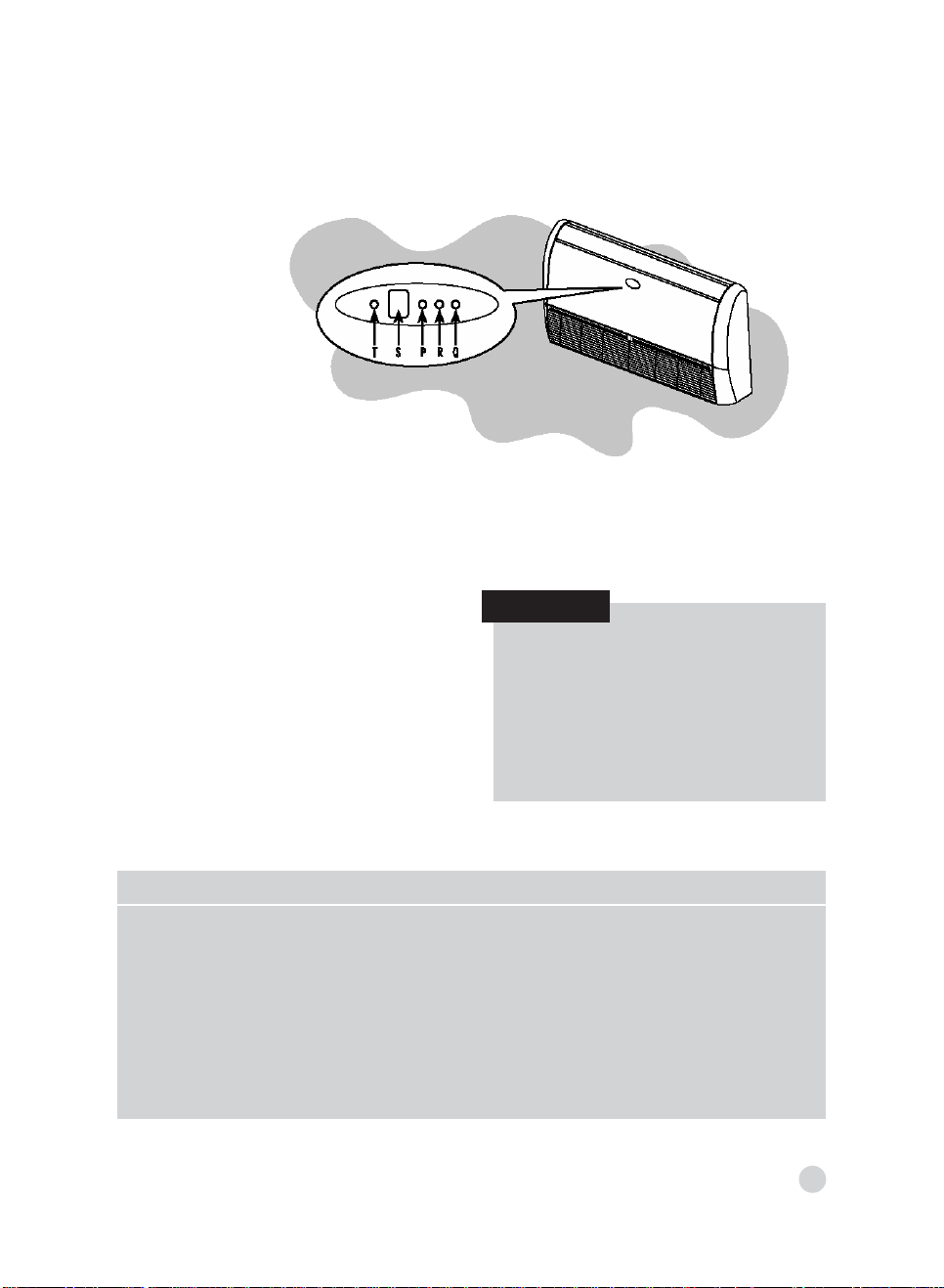
DISPLAYS OF THE INDOOR UNIT,
LED INDICATORS AND CONTROLS
T : EMERGENCY and RESET button
S : Receiver of remote control signal
P : Green LED
R : Yellow LED
Q : Red LED
Indoor Unit LEDs
Information about the operating mode of the
indoor unit is given by the 3 LEDs
(light-emitting diodes) on the unit.
THE GREEN LED (P) indicates the
followings:
• Error diagnosis.
• During normal operation, the LED is
illuminated.
ERROR CODE DESCRIPTION
3 Ambient temperature sensor error
4 Indoor unit coil sensor error
7 Outdoor unit error
10 EEPROM malfunction
11 Corrupted serial number
12 Incomplete address/zone information
13 Gas flow distribution error
NOTE
• When the unit is disconnected or in
Standby mode (waiting), the LED
remains switched off. If a breakdown
occurs, the LED flashes at 5-second
intervals. The error code is shown by
the number of times the LED flashes.
A pause of 5 seconds occurs between
the luminous signal cycles.
6

THE RED LED (Q) indicates the following
information
• During normal operation, the LED is
switched off.
• During defrosting, the LED is
illuminated.
• During the testing of the electrical
connections, the LED flashes at 1
second intervals.
THE YELLOW LED (R) indicates that the
unit is operating in timer mode. During this
operating mode, the LED is illuminated. If
timer mode is active and the unit is reset
immediately after a stop, this LED flashes
after receiving a new signal from the unit.
NOTE
• Positioning of the selector key: the
units leave the factory configured for
the underceiling position.
CONSOLE : Position 1
UNDERCEILING : Position 0
If in doubt, refer the Installation and
Start-up Instructions’ Manual.
“EMERGENCY button” (T)
This may be used when the remote control
is not working or has been lost.
Emergency Operation
When the unit is in OFF mode
(disconnected) and you press the
emergency button for 5 seconds, the unit
starts operating as follows:
• Automatic mode
• Temperature at 22
o
C
• Automatic fan speed
• The air deflectors are positioned
automatically according to the operating
mode – see note
• Timer deactivated during cleaning or
replacement of filter
NOTE
• According to the signal received via the
remote control, the unit starts operating
according to the command selected.
“RESET” (T)
This button must be pressed for one second
to revert to normal operation of the unit after
cleaning work or replacing the filter.
7
REMOTE CONTROL
The remote control works with 1.5 V
batteries. When the battery icon appears
on the display of the remote control, it’s time
to replace the old batteries.
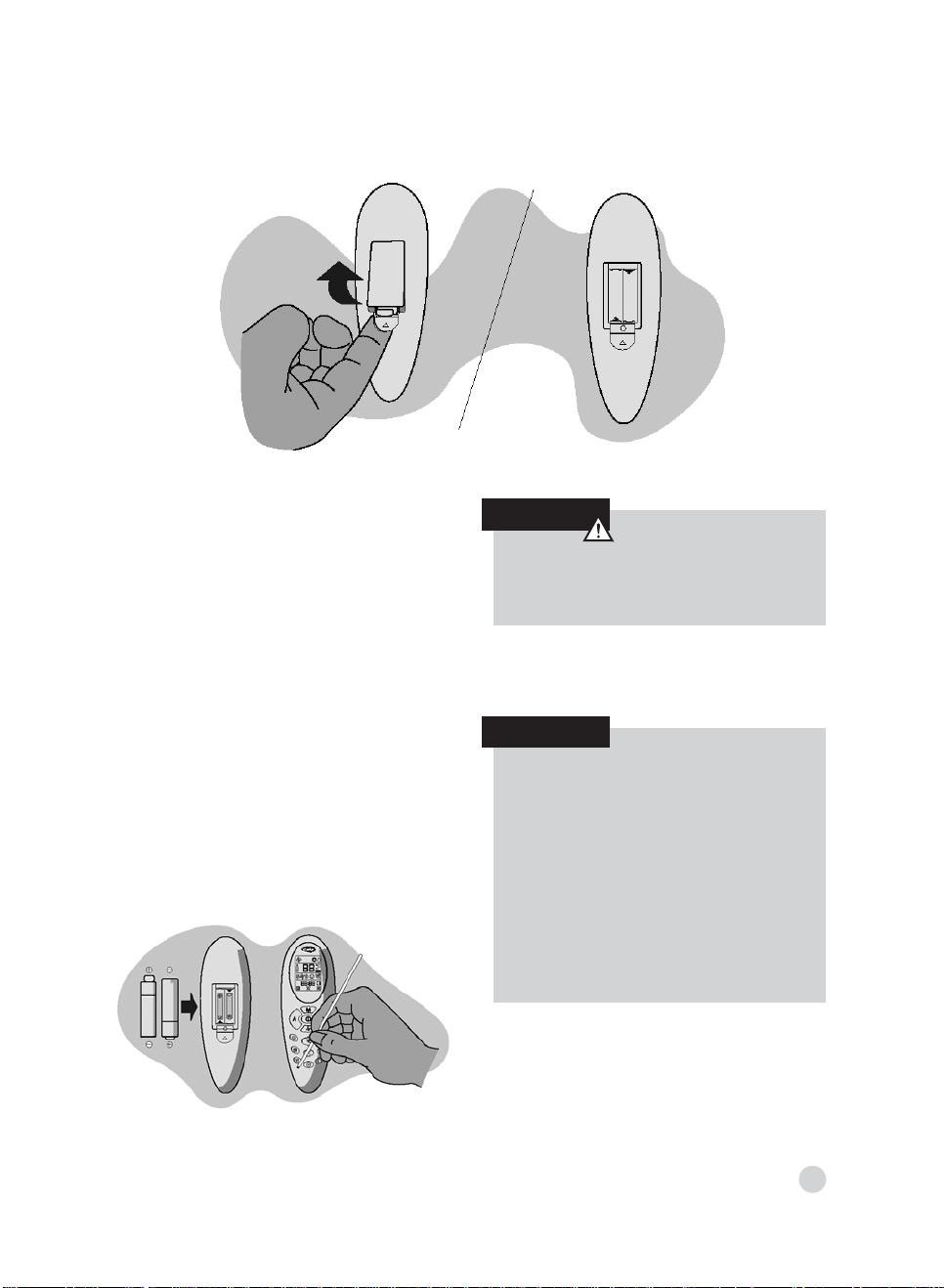
Inserting the batteries
• Open the battery compartment on the
back of the remote control. To remove
the small cover, press down the small
tab in the direction indicated by the
arrow in the diagram.
• Remove the old batteries and insert new
ones. The remote control requires two
batteries (1.5V type AAA).
• Press the “o” button with a sharppointed object to reset the remote
control.
CAUTION
Before replacing the batteries, the device
must be disconnected.
NOTE
• The average life of the batteries under
normal conditions of use is
approximately one year.
• If the air conditioner does not function
as normal after the remote control
batteries have been replaced, remove
the batteries again, reinsert them and
press the “o” button again after 5
seconds.
8
 Loading...