


OWNER’S MANUAL
High-Wall Fan Coil Unit
CONTENTS
Page
GENERAL. . . . . . . . . . . . . . . . . . . . . . . . . . . . . . . . . . . . . . .2,3 OPERATING MODES . . . . . . . . . . . . . . . . . . . . . . . . . . . . 2 REMOTE CONTROL. . . . . . . . . . . . . . . . . . . . . . . . . . . . . 2
OPERATION . . . . . . . . . . . . . . . . . . . . . . . . . . . . . . . . . . . 3-9 REMOTE CONTROL OPERATION . . . . . . . . . . . . . . . . 3 INDOOR UNIT DISPLAY . . . . . . . . . . . . . . . . . . . . . . . . . 5 EMERGENCY OPERATION . . . . . . . . . . . . . . . . . . . . . . 5 PRESSING THE ON/OFF BUTTON. . . . . . . . . . . . . . . . 5 SELECTING AN OPERATING MODE. . . . . . . . . . . . . . . 6 SETTING THE TEMPERATURE SET POINT . . . . . . . 6 SELECTING THE DIRECTION
OF LOUVER POSITION. . . . . . . . . . . . . . . . . . . . . . . . 6 SELECTING THE FAN SPEED . . . . . . . . . . . . . . . . . . . . 7 USING THE TURBO SETTING . . . . . . . . . . . . . . . . . . . 7 USING THE ECONOMICAL SETTING . . . . . . . . . . . . 7 SETTING THE ON TIMER. . . . . . . . . . . . . . . . . . . . . . . . 7 SETTING THE OFF TIMER. . . . . . . . . . . . . . . . . . . . . . . 8 SETTING THE DAILY TIMER . . . . . . . . . . . . . . . . . . . . 8 SETTING THE SLEEP TIMER . . . . . . . . . . . . . . . . . . . . 8 USING THE IONIZER FUNCTION . . . . . . . . . . . . . . . . 9 REMOTE CONTROL ADDRESS SELECTION . . . . . 9
Page RESETTING THE REMOTE CONTROL . . . . . . . . . . . 9 OPERATING CONDITIONS . . . . . . . . . . . . . . . . . . . . . . 9 TIME DELAY . . . . . . . . . . . . . . . . . . . . . . . . . . . . . . . . . . . 9 MINIMUM OPERATION TIME . . . . . . . . . . . . . . . . . . . 9 HEATING FEATURES. . . . . . . . . . . . . . . . . . . . . . . . . . . . 9 DEFROST OPERATION . . . . . . . . . . . . . . . . . . . . . . . . . . 9 AUTO RECOVERY . . . . . . . . . . . . . . . . . . . . . . . . . . . . . . 9 INDOOR UNIT FROST PREVENTION IN
COOLING AND DEHUMIDIFICATION
MODE. . . . . . . . . . . . . . . . . . . . . . . . . . . . . . . . . . . . . . . . 9
CLEANING, MAINTENANCE AND TROUBLESHOOTING . . . . . . . . . . . . . . . . . . . . . . . . . .9-11
PERIODIC MAINTENANCE. . . . . . . . . . . . . . . . . . . . . . 9 CLEANING THE COIL . . . . . . . . . . . . . . . . . . . . . . . . . . . 9 AIR FILTERS. . . . . . . . . . . . . . . . . . . . . . . . . . . . . . . . . . . 10 IONIZER . . . . . . . . . . . . . . . . . . . . . . . . . . . . . . . . . . . . . . . 10 INDOOR UNIT FRONT PANEL . . . . . . . . . . . . . . . . . . 10 PREPARING FOR A LONG SHUTDOWN PERIOD. . 10 SYSTEM OPERATION CHECK LIST . . . . . . . . . . . . . 10 ENERGY SAVING RECOMMENDATIONS. . . . . . . . 10 TROUBLESHOOTING . . . . . . . . . . . . . . . . . . . . . . . . . . . 10
Manufacturer reserves the right to discontinue, or change at any time, specifications or designs without notice and without incurring obligations.
Catalog No. OM38-40-7 |
Printed in U.S.A. |
Pg 1 |
Edition date: 3-08 |
Replaces: OM38/40-6 |

GENERAL
The high wall fan coil unit provides quiet, maximum comfort. In addition to cooling and/or heating, the high wall fan coil unit matched with an outdoor condensing unit will filter and dehumidify the air in the room to provide maximum comfort. See Fig. 1.
IMPORTANT: The high wall fan coil unit should be installed by authorized personnel only, using approved tubing and accessories. If technical assistance, service or repair is needed, contact the installer or call 1-800-227-7437.
The high wall fan coil unit can be set up and operated from the remote control (provided). See Fig. 2. If the remote is misplaced, the system can be operated from the “Auto” setting on the unit.
Operating Modes — The high wall fan coil unit has 5 operating modes:
•Fan only
•Auto (heat pump models only)
•Heating (heat pump models only)
•Cooling
•Dehumidification
FAN ONLY — In Fan Only mode, the system filters and circulates room air without changing room air temperature.
1 |
2 |
3 |
4 |
AUTO — In Auto mode, the system will automatically cool or heat the room according to the user selected set point.
If the room temperature is 2° F lower than the set point, the system will operate in Heating mode. If the room temperature is 2° F higher than the set point, the system will operate in Cooling mode.
HEATING — In Heating mode, the system heats and filters room air.
COOLING — In Cooling mode, the system cools, dries and filters room air.
DEHUMIDIFICATION — In Dehumidification mode, the system dries, filters and slightly cools room air temperature. This mode does not take the place of a dehumidifier.
NOTE: Two settings are available for use with selected modes. The Turbo setting provides maximum capacity. The Economical setting provides quiet, energy saving operation. Cooling and Heating modes can be operated in either the Turbo or the Economical setting. The Dehumidification mode can be operated in the Turbo setting, and the Auto mode can be operated in the Economical setting. See the Using the Turbo Setting or Using the Economical Setting sections for more information.
Remote Control (Fig. 2-6) — The remote control transmits commands to set up and operate the system. The controller has a window display panel that shows the current system status. The controller can be secured to a surface when used with the mounting rack provided. See Fig. 2.
5
LEGEND
A— Outdoor Unit
B— Indoor Unit
1— Automatic Swinging Louver
2— Air Filters
3— Remote Control Signal Receiver
4— Unit Operating Status Indicators
5— Interconnecting Tubing
6— Condensate Drain
6
Fig. 1 — Indoor and Outdoor Unit Components
2
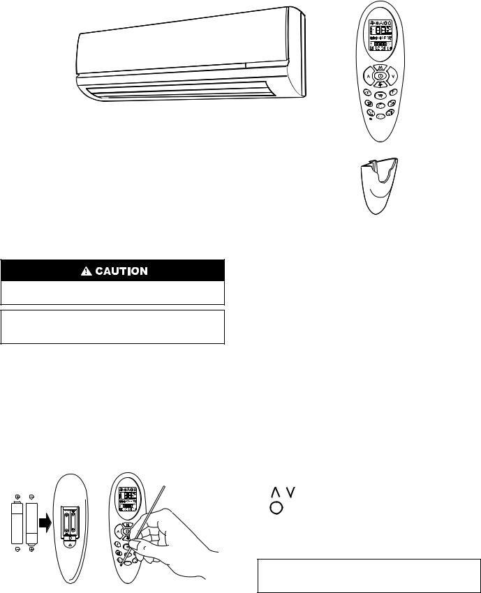
Fig. 2 — High Wall Fan Coil Unit and Remote Control
Handle the controller with care and avoid getting the controller wet. Damage to the device may result.
IMPORTANT: The remote control can operate the unit from a distance of up to 16 ft as long as there are not any obstructions.
The remote control can perform the following functions:
•Turn the system ON and OFF
•Select operating mode
•Adjust room air temperature set point and fan speed
•Set time periods for automatic system operation
BATTERY INSTALLATION — Two AAA 1.5-v alkaline batteries (included) are required for operation of the remote control. See Fig. 3 for battery location.
After new batteries have been inserted, press the reset button with a paper clip or the tip of a pen. Do not use old batteries or batteries of different types, as this may cause the
Fig. 3 — Location of Batteries on Remote Control
unit to malfunction. Batteries should only be changed after turning the unit off. The average battery life during normal use is approximately one year. If the air conditioner does not operate normally after replacing the batteries, refit the batteries and press the reset button again after 5 seconds.
To install batteries:
1.Remove battery compartment cover by pushing the tab up and removing it from the remote.
2.Insert batteries being sure to follow polarity markings inside battery compartment.
3.Replace battery compartment cover.
NOTE: Replace batteries whenever “Low battery” indicator appears on remote control display panel. See Fig. 4.
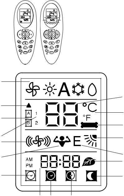
DISPLAY SCREEN — There are five operating mode indicators that appear on the remote control display screen. See Fig. 4.
OPERATION
Remote Control Operation — The remote control has 3 buttons (see Fig. 5) used for operating and controlling the system:
• — changes operating mode
• — adjust temperature
• |
|
— turns the system on or off. |
|
NOTE: When transmitting a command from the remote control to the unit, be sure to point the controller toward the right side of the unit. See Fig. 6. The unit will confirm receipt of a command by sounding an audible beep.
IMPORTANT: If no changes are made within 10 seconds, the remote control will return to its previous setting.
3
SETTING THE TIME ON THE REMOTE CONTROL (Current Time Adjusting C and Reset Buttons) — Press current time adjusting button C to adjust the current time. Press the reset button with the tip of a pen or a paperclip if the remote control is not operating properly or after replacing the batteries.
1. With the remote control ON or OFF, press C for at least 5 seconds.
2. The current hour flashes. Press either  or
or  to set the current hour. Press C again to move to set the minutes.
3. Once the current time is set, press C to confirm it.
FAN SPEED — To select the Fan mode and change the Fan Speed, follow the steps below:
1.Press the Mode button to select the Fan mode.
2.Press the Fan Speed button to select desired fan speed.
NOTE: If unit is operating in Dehumidification mode the fan will only operate in low speed and cannot be changed.
TEMPERATURE SETTINGS — The temperature set point can be easily changed by pointing the controller toward the unit and pressing the increase/decrease temperature set point buttons until the desired temperature appears on screen.
AIRFLOW DIRECTION — The louvers can be manually operated by pressing the Louver button to change airflow direction. Refer to Table 1 for louver positions.
1 |
|
|
|
|
3 |
2 |
|
|
|
|
5 |
4 |
|
|
|
|
7 |
6 |
|
8 |
9 |
|
|
|
|
|
10 |
|
11 |
|
17 |
|
|
|
|
12 |
|
13 |
15 |
16 |
14 |
1.Operating mode (from left to right)  Fan only
 Heating (heat pump models only)
 Automatic (heat pump models only)
 Cooling
 Dehumidification
2.Signal transmission symbol
3.Temperature set point selected
4.Address selected
5.Temperature unit of measurement (°C or °F)
6.Unit configuration
7.Low Battery indicator
8.Louver position
9.Fan speed
10.Turbo setting
11.Economical setting
12.ON timer selected
13.Night timer active
14.DAILY timer active (Everyday)
15.ON timer and OFF timer or current time
16.OFF timer selected
17.Ionizer active
Fig. 4 — Remote Control Display Icons
4
 Loading...