


38HDL018-060 Light Commercial Condensing Units
Installation, Start-Up and
Service Instructions
CONTENTS
Page
SAFETY CONSIDERATIONS . . . . . . . . . . . . . . . . . . . 1
INSTALLATION . . . . . . . . . . . . . . . . . . . . . . . . . . . . . . 1-7
Step 1 Ð Complete Pre-Installation
Checks . . . . . . . . . . . . . . . . . . . . . . . . . . . . . . . . . . . . 1
·UNPACK UNIT
·INSPECT SHIPMENT
·CONSIDER SYSTEM REQUIREMENTS
Step 2 Ð Rig and Mount Unit . . . . . . . . . . . . . . . . . 3
·MOUNTING ON GROUND
·MOUNTING ON ROOF
·RIGGING
Step 3 Ð Complete Refrigerant Piping
Connections . . . . . . . . . . . . . . . . . . . . . . . . . . . . . . . 3
·CHECK ACCURATERt CONTROL
·MAKE PIPING SWEAT CONNECTIONS
·PROVIDE SAFETY RELIEF
Step 4 Ð Make Electrical Connections . . . . . . . . 4
·POWER WIRING
·CONTROL CIRCUIT WIRING
·CONNECTIONS TO DUCT-FREE FAN COIL UNITS
Step 5 Ð Accessory Installation . . . . . . . . . . . . . . 4
START-UP . . . . . . . . . . . . . . . . . . . . . . . . . . . . . . . . . . . 7 SERVICE . . . . . . . . . . . . . . . . . . . . . . . . . . . . . . . . . . . 7-9 MAINTENANCE . . . . . . . . . . . . . . . . . . . . . . . . . . . . . 10 TROUBLESHOOTING . . . . . . . . . . . . . . . . . . . . . . . . 11
SAFETY CONSIDERATIONS
Install and servicing air-conditioning equipment can be hazardous due to system pressure and electrical components. Only trained and quali®ed service personnel should install or service air-conditioning equipment
Untrained personnel may perform basic maintenance such as cleaning and replacing ®lters. All other operations should be performed by trained service personnel. When working on air-conditioning equipment, observe safety precautions in literature, and on tags and labels attached to unit.
Follow all safety codes. Wear safety glasses and work gloves. Use quenching cloth for brazing operations. Have a ®re extinguisher available. Read these instructions thoroughly. Consult local building codes and National Electrical Code (NEC, U.S.A. Standard) for special installation requirements.
COOLING
Fig. 1 Ð 38HDL Condensing Unit
Before installing or servicing system, always turn off main power to system. There may be more than one disconnect switch. Turn off accessory heater power if applicable. Electrical shock can cause personal injury.
Step 1 Ð Complete Pre-Installation Checks
UNPACK UNIT Ð Move unit to ®nal location. Remove carton from unit, being careful not to damage service valves or grilles.
INSPECT SHIPMENT Ð File claim with shipping company if shipment is damaged or incomplete. Check unit nameplate to ensure unit matches job requirements.
CONSIDER SYSTEM REQUIREMENTS Ð Consult local building codes and NEC for special installation requirements.
Allow sufficient space for air¯ow clearance, wiring, refrigerant piping, and servicing unit. See Fig. 1 and 2. Unit can be mounted on a level pad directly on base legs or mounted on raised pads at support points. See Fig. 2 for center of gravity.
Manufacturer reserves the right to discontinue, or change at any time, speci®cations or designs without notice and without incurring obligations.
Book |
1 |
4 |
|
PC 111 |
Catalog No. 563-899 |
Printed in U.S.A. |
Form 38HDL-1SI |
Pg 1 |
9-98 |
Replaces: New |
Tab |
3a |
2a |
|
|
|
|
|
|
|
|
|
|
|
|
|
|
|
|
|
|
|

UNIT |
A |
|
B |
|
C |
|
D |
|
E |
|
F |
|
|
G |
H |
|
J |
|
|
K |
|
L |
|
|
M |
OPERATING |
|||||||||||
SIZE |
|
|
|
|
|
|
|
|
|
|
|
|
|
|
|
|
|
|
|
|
|
|
|
|
|
|
|
|
|
|
|
|
|
|
|
WEIGHT |
|
38HDL |
ft-in. |
|
mm |
ft-in. |
|
mm |
ft-in. |
|
mm |
ft-in. |
|
mm |
ft-in. |
mm |
ft-in. |
|
mm |
ft-in. |
|
mm |
ft-in. |
|
mm |
ft-in. |
mm |
ft-in. |
|
mm |
ft-in. |
|
mm |
ft-in. |
mm |
lb |
kg |
||
018 |
2-11¤8 |
|
638.2 |
3-015¤16 |
|
938.2 |
1-29¤16 |
|
369.9 |
1-4 |
|
406.4 |
1-117¤16 |
595.3 |
1-53¤16 |
|
436.6 |
1-51¤2 |
|
444.5 |
1-81¤8 |
|
511.2 |
1-1 |
330.2 |
0-65¤8 |
|
168.3 |
0-111¤4 |
|
285.8 |
0-05¤8 |
|
15.88 |
130 |
58.9 |
|
024 |
2-11¤8 |
|
638.2 |
3-015¤16 |
|
938.2 |
1-29¤16 |
|
369.9 |
1-4 |
|
406.4 |
1-117¤16 |
595.3 |
1-53¤16 |
|
436.6 |
1-51¤2 |
|
444.5 |
1-81¤8 |
|
511.2 |
1-1 |
330.2 |
0-63¤4 |
|
171.5 |
0-115¤8 |
|
295.3 |
0-05¤8 |
|
15.88 |
136 |
61.6 |
|
030 |
2-11¤8 |
|
638.2 |
3-015¤16 |
|
938.2 |
1-29¤16 |
|
369.9 |
1-4 |
|
406.4 |
1-117¤16 |
595.3 |
1-53¤16 |
|
436.6 |
1-51¤2 |
|
444.5 |
1-81¤8 |
|
511.2 |
1-1 |
330.2 |
0-63¤4 |
|
171.5 |
0-115¤8 |
|
295.3 |
0-03¤4 |
|
19.05 |
161 |
73.0 |
|
036 |
2-11¤8 |
|
638.2 |
3-015¤16 |
|
938.2 |
1-29¤16 |
369.9 |
1-4 |
|
406.4 |
1-117¤16 |
595.3 |
1-53¤16 |
|
436.6 |
1-51¤2 |
|
444.5 |
1-81¤8 |
|
511.2 |
1-1 |
330.2 |
0-63¤4 |
|
171.5 |
0-115¤8 |
|
295.3 |
0-03¤4 |
|
19.05 |
185 |
83.9 |
||
048 |
3-13¤16 |
|
944.6 |
3-89¤16 |
|
1131.9 |
1-51¤16 |
433.4 |
1-67¤16 |
|
468.3 |
2- 61¤2 |
774.7 |
1-75¤8 |
|
498.5 |
2-55¤8 |
|
752.5 |
2-83¤16 |
|
817.6 |
1-17¤8 |
352.4 |
0-81¤4 |
|
209.5 |
0- |
4 |
|
406.4 |
0-07¤8 |
|
22.22 |
222 |
100.5 |
|
060 |
3-13¤16 |
|
944.6 |
3-89¤16 |
|
1131.9 |
1-51¤16 |
|
433.4 |
1-67¤16 |
|
468.3 |
2- 61¤2 |
774.7 |
1-75¤8 |
|
498.5 |
2-55¤8 |
|
752.5 |
2-83¤16 |
|
817.6 |
1-111¤16 |
347.7 |
0-81¤8 |
|
206.4 |
0- |
37¤8 |
|
403.2 |
0-07¤8 |
|
22.22 |
249 |
112.9 |
PAD DIMENSIONS
|
|
|
|
Stand |
Ice Stand |
|
|
|
|
|
mm |
ft-in. |
mm |
|
|
|
|
660.4 x 1066.8 |
2-2 x 3-6 |
660.4 x 1066.8 |
|
|
|
|
|
|
|
|
|
|
|
711.2 x 1270.0 |
2-2 x 4-2 |
660.4 x 1270.0 |
|
|
|
|
|
|
|
.4 mm) minimum clearance on coil side and compressor end and fan side. With fan facing and coil end, and 3 ft (914.4 mm) minimum -unit application, arrange units so discharge of
2
Fig. 2 Ð 38HDL018-060 Ð Dimensional Drawing
Step 2 Ð Rig and Mount Unit
MOUNTING ON GROUND Ð Mount unit on a solid, level concrete pad. Position unit so water or ice from roof does not fall directly into unit. Field-fabricated stacking kits can be used when units are to be stacked. If conditions or local codes require unit to be fastened to a pad, 6 ®eld-supplied tiedown bolts should be used and fastened through slots provided in unit mounting feet.
MOUNTING ON ROOF Ð Mount unit on level platform or frame at least 6 in. (154 mm) above roof surface. Isolate unit and tubing from structure.
RIGGING
Be sure unit panels are securely in place prior to rigging.
Keep unit upright. Lift unit using sling. Use cardboard or padding under sling, and spreader bars to prevent sling damage to unit. See Fig. 3. See Fig. 2 for center of gravity reference. Install unit so coil does not face into prevailing winds. If this is not possible and constant winds above 25 mph are expected, use ®eld-fabricated wind baffle.
NOTE: Field-fabricated wind baffles should be used on all units with accessory low-ambient control.
Field-fabricated snow stand may be used to raise unit when operation will be required during the winter. Units may also be wall mounted using the accessory wall mounting kit.
Step 3 Ð Complete Refrigerant Piping Connec-
tions Ð Outdoor units may be connected to indoor units using ®eld-supplied tubing of refrigerant grade and condition. See Tables 1A and 1B for correct line sizes. Do not use less than 10 ft (3 m) of interconnecting tubing.
DO NOT BURY MORE THAN 36 IN. (922 mm) OF REFRIGERANT PIPE IN THE GROUND. If any section of pipe is buried, there must be a 6 in. (154 m) vertical rise to the valve connections on the outdoor unit. If more than the recommended length is buried, refrigerant may migrate to the cooler, buried section during extended periods of system shutdown. This causes refrigerant slugging and could damage compressor at start-up.
When more than 50 ft (15.2 m) of interconnecting tubing and more than 30 ft (9.1 m) of vertical lift is used, refer to Part 3 of the Carrier System Design Manual for design details, or contact your local distributor.
If either refrigerant tubing or indoor coil is exposed to atmospheric conditions for longer than 5 minutes, it must be evacuated to 1000 microns to eliminate contamination and moisture in the system.
Run refrigerant tubes as directly as possible, avoiding unnecessary turns and bends. Suspend refrigerant tubes so they do not damage insulation on vapor tube and do not transmit vibration to the structure. Also, when passing refrigerant tubes through the wall, seal opening so that vibration is not transmitted to structure. Leave some slack in refrigerant tubes between structure and outdoor unit to absorb vibration. Refer to separate indoor unit installation instructions for additional information.
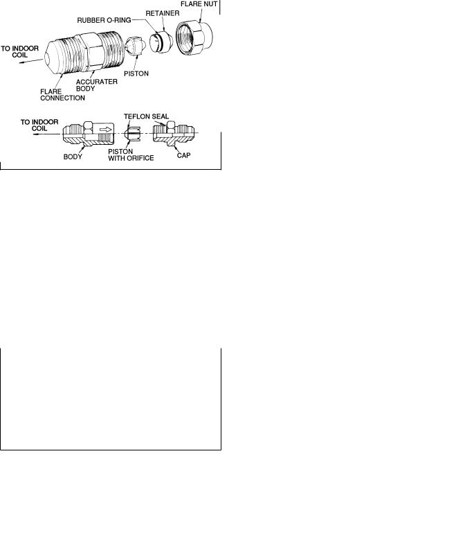
CHECK ACCURATERt CONTROL Ð The correct AccuRater (bypass type) refrigerant control is required for cooling system capacity optimization. An AccuRater device
Fig. 3 Ð Lifting Unit with Sling
with ®eld-replaceable piston should be supplied with the indoor unit. Refer to AccuRater metering device table in separate indoor unit installation instructions to determine the correct AccuRater piston size required for the condenser/evaporator system being installed.
Note that one of 2 types of the AccuRater devices can be found on the indoor unit. See Fig. 4. Do not interchange components between AccuRater device types. Matching of outdoor unit with indoor unit may require ®eld replacement of piston. Replace piston, if required, before connecting refrigerant lines. Piston replacement instructions are included in the indoor unit installation instructions. After system installation is complete, see Refrigerant charging section on page 8 to check and/or adjust refrigerant charge.
The 38HDL018-060 units may also be installed with units using a thermostatic expansion valve (TXV). If a TXV is used, be sure to remove the piston from the indoor coil. See installation instructions shipped with the TXV for proper positioning and adjustment.
TYPE A (BYPASS TYPE)
TYPE B
NOTE: Arrow on AccuRater body points in free-¯ow direction, away from the indoor coil.
Fig. 4 Ð AccuRater Metering Device Components
MAKE PIPING SWEAT CONNECTIONS Ð Remove plastic caps from liquid and suction service valves. Use refrigerant grade tubing. Service valves are closed from the factory and ready for brazing. After wrapping the service valve
3
with a wet cloth, the tubing set can be brazed to the service valve using either silver bearing or non-silver bearing brazing material. Consult local code requirements. Refrigerant tubing and indoor coil are ready for leak testing.
NOTE: Unit is shipped with R-22 full factory charge indicated on nameplate.
Pass nitrogen or other inert gas through piping while brazing to prevent formation of copper oxide.
To avoid damage while brazing, service valves should be wrapped in a heat-sinking material such as a wet cloth.
When brazing tubing sets to the service valves, a brazing shield must be used to prevent damage to the painted unit surface.
PROVIDE SAFETY RELIEF Ð A fusible plug is located in unit suction line; do not cap this plug. If local code requires additional safety devices, install as directed.
Step 4 Ð Make Electrical Connections
Unit cabinet must have an uninterrupted, unbroken electrical ground to minimize the possibility of personal injury if an electrical fault should occur. This ground may consist of electrical wire connected to the unit ground lug in control compartment, or conduit approved for electrical ground when installed in accordance with NEC, ANSI/NFPA (American National Standards Institute/National Fire Protection Association) 70 (U.S.A. Standards), and local electrical codes. Failure to follow this warning could result in the installer being liable for personal injury to others.
Unit failure as a result of operation on improper line voltage or excessive phase imbalance constitutes abuse and may cause damage to electrical components. Such operation will invalidate any applicable Carrier warranty.
POWER WIRING Ð Unit is factory-wired for voltage shown on nameplate. Provide adequate, fused disconnect switch within sight of unit, readily accessible but out of reach of children. Provision for locking the switch open (off) is advisable to prevent power from being turned on while unit is being serviced. Disconnect switch, fuses, and ®eld wiring must be
in compliance with NEC (U.S.A. Standard) and applicable local codes. Use minimum 60 C wire for ®eld power connection.
Route power wires through opening in the unit side panel and connect in unit control box as shown on unit label diagram and Fig. 5 and 6. Unit must be grounded.
CONTROL CIRCUIT WIRING Ð Control voltage is 24 v. See Fig. 5 and unit label diagram for ®eld-supplied wiring details. Route control wire through opening in the unit side panel to connection in unit control box.
NOTE: For wire runs up to 50 ft (15 m), use no. 18 AWG (American Wire Gage) insulated wire (35 C minimum). For 50 to 75 ft (15 to 23 m), use no. 16 AWG insulated wire. For more than 75 ft (23 m), use no. 14 AWG insulated wire. See Table 2 for conversion to European wire sizes.
NOTE: Operation of unit on improper line voltage constitutes abuse and could affect Carrier warranty. See Table 3. Do not install unit in system where voltage may ¯uctuate above or below permissible limits.
See Table 3 for recommended fuse sizes. When making electrical connections, provide clearance at unit for refrigerant piping connections.
Use indoor unit transformer as 24-v (40-va minimum) supply for system as shown in Fig. 5 or use accessory transformer.
Before performing service or maintenance, be sure the indoor unit main power switch is off and indoor blower has completely stopped. Failure to do so may result in electrical shock or injury from rotating fan blades.
CONNECTIONS TO DUCT-FREE FAN COIL UNITS Ð The 38HDL units are designed for easy match-up to 40QAB, 40QKB, and 40QNB018,024 duct-free fan coils. These units provide 24-v power for the outdoor unit from the fan coil. Connect the Y and C terminals of the indoor unit to the blue and brown wires of the outdoor unit with 20 gage (minimum) thermostat wire.
Step 5 Ð Accessory Installation Ð Install all unit accessories per accessory installation instructions prior to start-up.
Do not use accessory Time Guardt II device when combining a 38HDL unit with 40QNB indoor units.
When ambient temperature will fall below 55 F (13 C), accessory low ambient controller (part no. 53DS900060) is required. When accessory low ambient kit is used, unit should also be equipped with accessory winter start kit and ®eldfabricated wind baffles.
4
 Loading...