


38GJ
Owner's Manual & Installation Instructions
TABLE OF CONTENTS
SAFETY CONSIDERATIONS ......................... 2
SYSTEM REQUIREMENTS .......................... 2
Preface ............................................. 3
2 Product Introduction ................................ 4
2.1 Name of Main Parts ............................... 4
2.2 Combinations for outdoor and indoor traits ............ 5
2.3 Rated working condition ........................... 6
2.4 The range of production working temperature ........... 6
3 Preparation before Installation .......................... 7
3.1 Standard parts ................................... 7
3.2 Selecting installation site ........................... 7
3.3 Piping Connection ................................ 8
4 Installation ........................................ 9
4.1 Outline and dimension of the outdoor unit ............. 9
4.2 Installation of the Connection Pipe ................. 10
4.3 Air Purgingand Refrigerant Charge .................. 14
4.4 Electric Wiring .................................. 15
5 Troubleshooting .................................... 17
6 The conditions listed below are not classified into errors ..... 18
NOTE: Read the entire instruction manual before starting the
installation.
7 Troubleshooting .................................... 20
8 Maintenance ...................................... 21
PAGE
NOTE TO EQUIPMENT OWNER:
Please read this Owner's Information Manual carefully before installing and using this appliance
and keep this manual for future reference.
For your convenience, please record the model and serial numbers of your new equipment in the
spaces provided. This information, along with the installation data and dealer contact information,
will be helpful should your system require maintenance or service.
UNIT INFORMATION
Model #
Serial #
INSTALLATION INFORMATION
Date Installed
DEALERSHIP CONTACT INFORMATION
Company Name:
Address:
Phone Number:
Technician Name:
SAFETY CONSIDERATIONS
Installing, starting up, and servicing air-conditioning equipment
can be hazardous due to system pressures, electrical components,
and equipment location (roofs, elevated structures, etc.).
Only trained, qualified installers and service mechanics should
install, start-up, and service this equipment.
Untrained personnel can perform basic maintenance flmctions such
as cleaning coils. All other operations should be performed by
trained service personnel.
When working on the equipment, observe precautions in the
literature and on tags, stickers, and labels attached to the
equipment.
Follow all safety codes. Wear safety glasses and work gloves. Keep
quenching cloth and fire extinguisher nearby when brazing. Use
care in handling, rigging, and setting bulky equipment.
Read these instructions thoroughly and follow all warnings or
cautions included in literature and attached to the unit. Consult
local building codes and National Electrical Code (NEC) for
special requirements. Recognize safety information. This is the
safety-alert symbol/}k When you see this symbol on the unit and
in instructions or manuals, be alert to the potential for personal
injury.Understand these signal words: DANGER, WARNING, and
CAUTION. These words are used with the safety-alert symbol.
DANGER identifies the most serious hazards which will result in
severe personal injury or death. WARNING signifies hazards
which could result in personal injury or death. CAUTION is used
to identify unsafe practices which may result in nfinor personal
injury or product and property damage. NOTE is used to highlight
suggestions which will result in enhanced installation, reliability, or
operation.
ELECTRICALSHOCK HAZARD
Failure to follow this warning could result in personal
injury or death.
Before installing, modifying, or servicing system, main
electrical disconnect switch must be in the OFF
position. There may be more than 1 disconnect switch.
Lock out and tag switch with a suitable warning label.
EXPLOSION HAZARD
Failure to follow this warning could
result in death, serious personal injury,
and/or property damage.
Never use air or gases containing
oxygen for leak testing or operating
refrigerant compressors. Pressurized
nfixtures of air or gases containing
oxygen can lead to an explosion.
EQUIPMENT DAMAGE HAZARD
Failure to follow this caution may result in equipment
damage or improper operation.
Do not bury more than 36 in. (914 ram) of refrigerant pipe
in the ground. If any section of pipe is buried, there must be
a 6 in. (152 ram) vertical rise to the valve connections on
the outdoor units. If more than the recommended length is
buried, refrigerant may nfigrate to the cooler buried section
during extended periods of system shutdown. This causes
refrigerant slugging and could possibly damage the
compressor at start-up.
SYSTEM REQUIREMENTS
Allow sufficient space for airflow and servicing unit. See
minimum required distances between unit and walls or
ceilings,
Recommended Connection Method for Power and Communi-
cation Wiring (To minimize communication wiring interfer-
ence)
Power Wiring:
The main power is supplied to the outdoor unit. The field supplied
connecting cable from the outdoor unit to indoor unit consists of
three (3) wires and provides the power for the indoor unit. Two
wires are high voltage AC power and one is a ground wire.
Consult your local building codes and the NEC (National
Electrical Code) or CEC (Canadian Electrical Code) for special
requirements.
All wires must be sized per NEC or CEC and local codes. Use
Electrical Data table MCA (minimum circuit amps) and MOCP
(maximum over current protection) to correctly size the wires and
the disconnect fuse or breakers respectively.
Per caution note, only copper conductors with a minimum 300 volt
rating and 2/64-inch thick insulation must be used.
Communication Wiring:
A separate shielded copper conductor only, with a minimum 300
volt rating and 2/64-inch thick insulation, must be used as the
communication wire from the outdoor unit to the indoor unit.
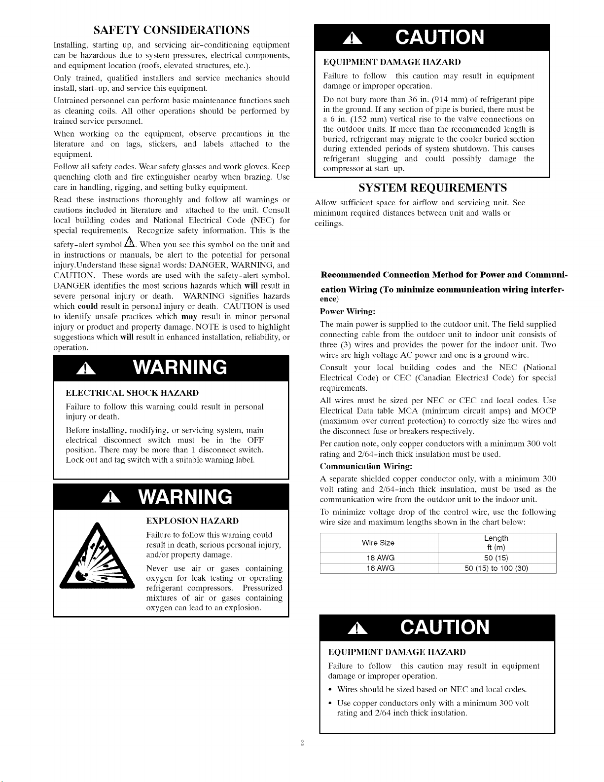
To nfininfize voltage drop of the control wire, use the following
wire size and maximum lengths shown in the chart below:
Wire Size Length
18 AWG 50 (15)
16 AWG 50 (15) to 100 (30)
ft (m)
EQUIPMENT DAMAGE HAZARD
Failure to follow this caution may result in equipment
damage or improper operation.
• Wires should be sized based on NEC and local codes.
• Use copper conductors only with a minimum 300 volt
rating and 2/64 inch thick insulation.
Preface
Please carefully read the instructions in this manual before installation and operation.
(1) This unit measures onthe base of UL1995.
(2) Multi-zone air conditioning units confirm to des ign s tandard: AHRI 210240- 2008.
(3) For personal safety, please follow the instructions provided in this manual.
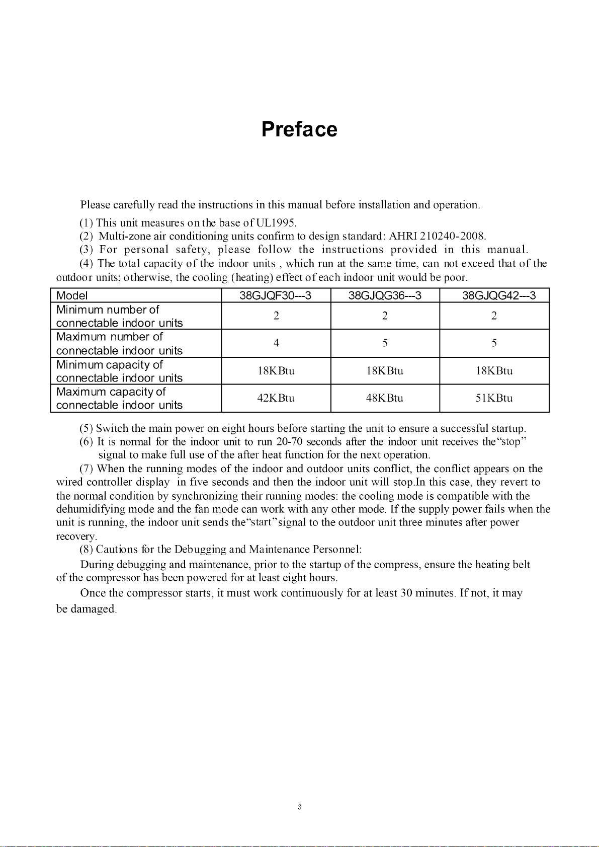
(4) The total capacity of the indoor units , which run at the same time, can not exceed that of the
outdoor units; otherwise, the cooling (heating) effect of each indoor unit would be poor.
Model 38GJQF30--3 38GJQG36--3 38GJQG42--3
Minimum number of
connectable indoor units
Maximum number of
connectable indoor units
Minimum capacity of
connectable indoor units
Maxim um capacity of 42KBtu 48KBtu 51KBtu
connectable indoor units
2 2 2
4 5 5
18KBtu 18KBtu 18KBtu
(5) Switch the main power on eight hours before starting the unit to ensure a successful startup.
(6) It is normal for the indoor unit to run 20-70 seconds after the indoor unit receives the"stop"
signal to make full use of the after heat function for the next operation.
(7) When the running modes of the indoor and outdoor units conflict, the conflict appears on the
wired controller display in five seconds and then the indoor unit will stop.In this case, they revert to
the normal condition by synchronizing their running modes: the cooling mode is compatible with the
dehumidifying mode and the fan mode can work with any other mode. If the supply power fails when the
unit is running, the indoor unit sends the"start'signal to the outdoor unit three minutes after power
recovery.
(8) Cautions for the Debugging and Maintenance Personnel:
During debugging and maintenance, prior to the startup of the compress, ensure the heating belt
of the compressor has been powered for at least eight hours.
Once the compressor starts, it must work continuously for at least 30 minutes. If not, it may
be damaged.
2 Product Introduction
The 38GJ system adopts inverter compressor technology. According to change displacement of
compressor, stepless capacity regulation within range of 15%-120% can be realized. Various product lineup is
provided with capacity range from 30KBtu to 42KBtu, which can be widely used in a boarding house, a working area
and especially applicable in a location with a variable load change.
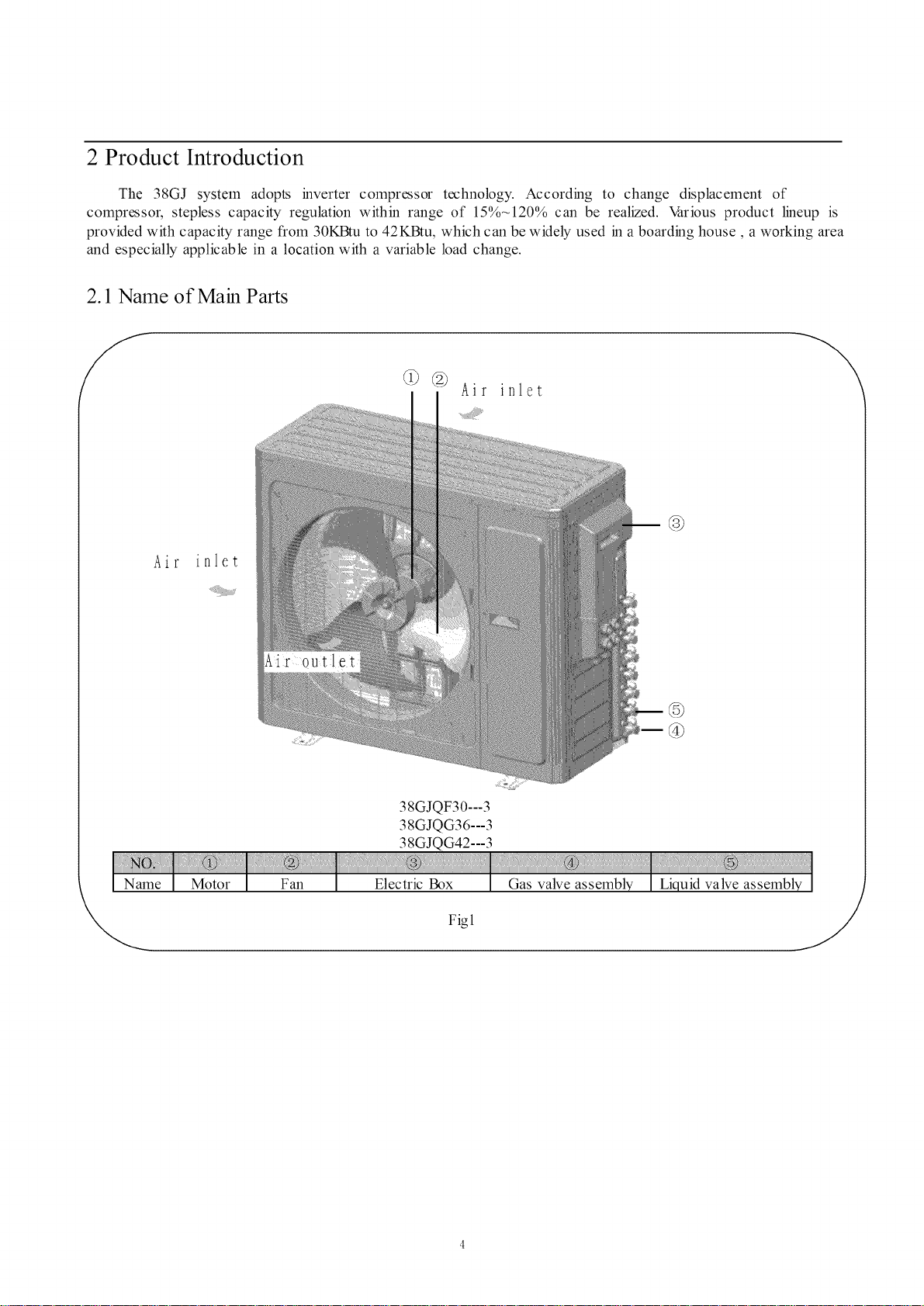
2.1 Name of Main Parts
@ @ Air inlet
@
Air
\
@
38GJQF30---3
38 GJQ G36 --- 3
38GJQG42---3
Fig1
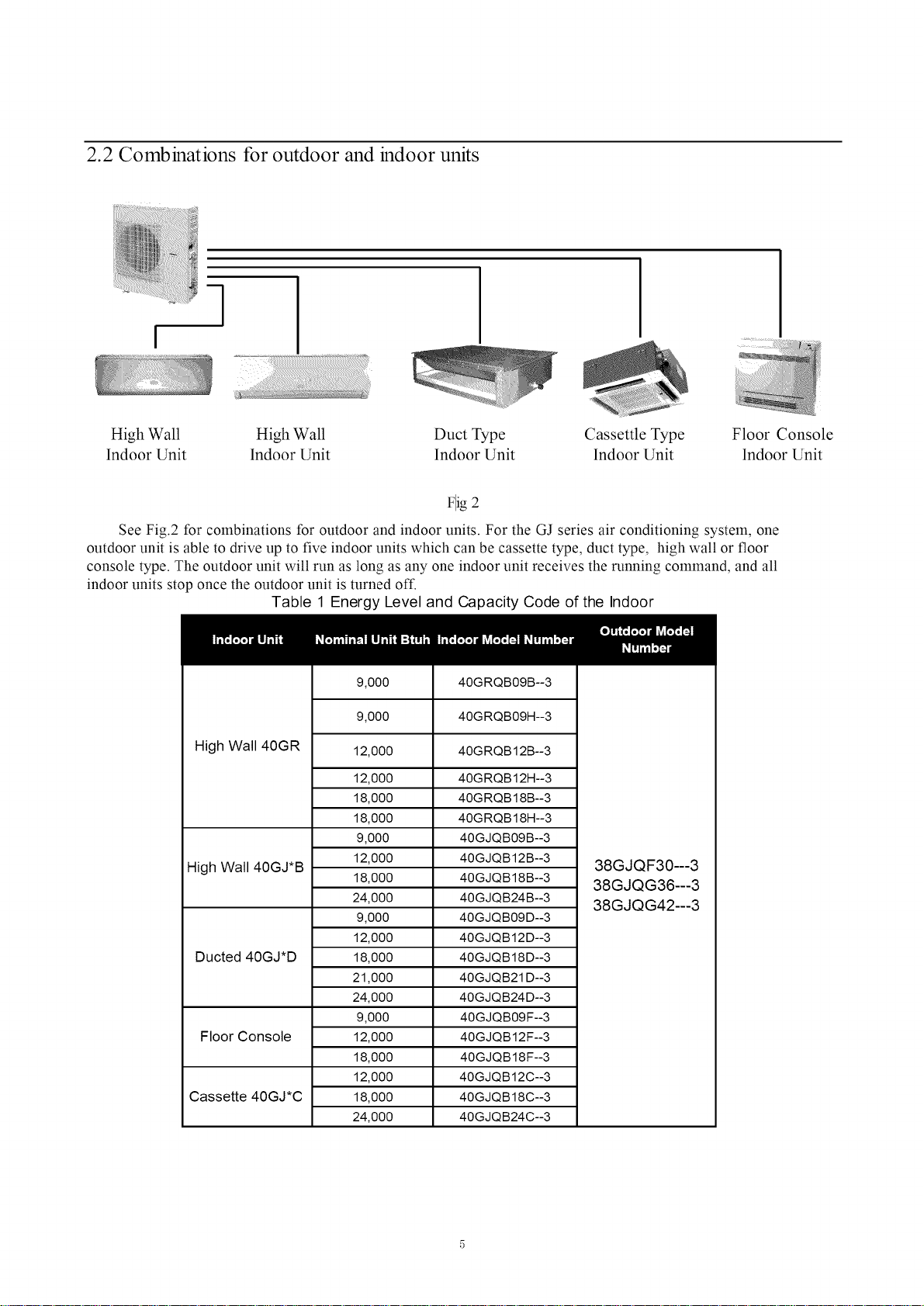
2.2 Combinations for outdoor and indoor units
q
High Wall High Wall Duct Type Cassettle Type Floor Console
lndoor Unit lndoor Unit lndoor Unit lndoor Unit lndoor Unit
Flig 2
See Fig.2 for combinations for outdoor and indoor units. For the GJ series air conditioning system, one
outdoor unit is able to drive up to five indoor units which can be cassette type, duct type, high wall or floor
console type. The outdoor unit will run as long as any one indoor unit receives the running command, and all
indoor units stop once the outdoor unit is turned off.
Table 1 Energy Level and Capacity Code of the Indoor
High Wall 40GR
High Wall 40GJ*B
Ducted 40GJ*D
Floor Console
Cassette 40GJ*C
9,000
9,000
12,000
12,000
18,000
18,000
9,000
12,000
18,000
24,000
9,000
12,000
18,000
21,000
24,000
9,000
12,000
18,000
12,000
18,000
24,000
40GRQB09B--3
40GRQB09H--3
40GRQB12B--3
40GRQB12H--3
40GRQB18B--3
40GRQB18H--3
40GJQB09B--3
40GJQB12B--3
40GJQB18B--3
40GJQB24B--3
40GJQB09D--3
40GJQB12D--3
40GJQB18D--3
40GJQB21 D--3
40GJQB24D--3
40GJQB09F--3
40GJQB12F--3
40GJQB18F--3
40GJQB12C--3
40GJQB18C--3
40GJQB24C--3
38GJQF30---3
38GJQG36---3
38GJQG42---3
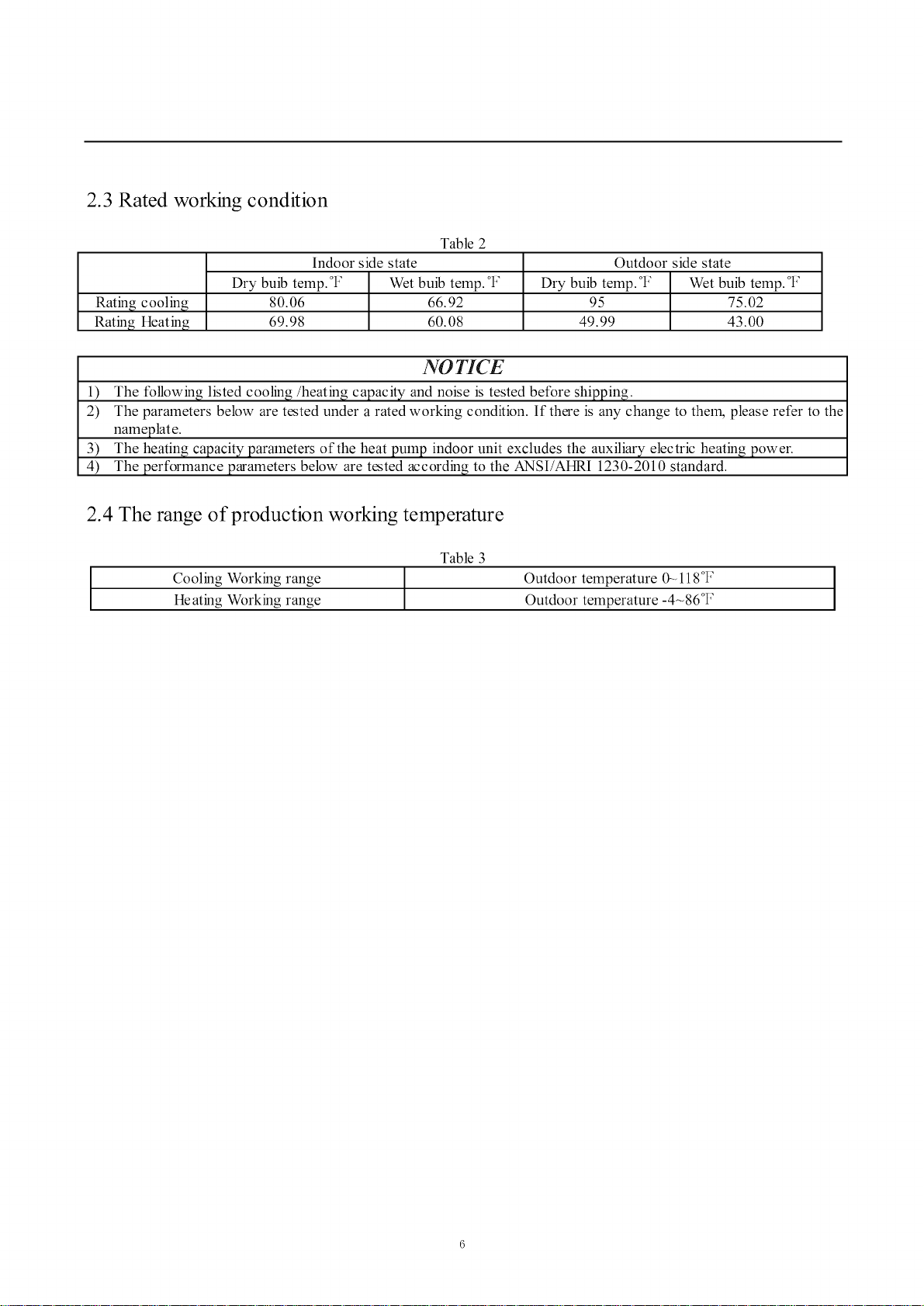
2.3 Rated working condition
Table 2
Rating cooling
Rating Heating
Indoor side state
Dry buib temp. °t: Wet buib temp. °t:
80.06 66.92
69.98 60.08
Dry buib temp. °F Wet buib temp. °F
Outdoor side state
95 75.02
49.99 43.00
NO TICE
1) The following listed cooling/heating capacity and noise is tested before shipping.
2) The parameters below are tested under a rated working condition. If there is any change to thel_ please refer to the
nameplate.
3) The heating capacity parameters of the heat pump indoor unit excludes the auxiliary electric heating power.
4) The performance parameters below are tested according to the ANSI/AHRI 1230-2010 standard.
2.4 The range of production working temperature
Table 3
Cooling Working range Outdoor temperature 0_ 118°F ]
Heating Working range Outdoor temperature -4-86°F
I
3 Preparation before Installation
3.1 Standard parts
Please use the following standard parts included with the air conditioning units.
Table 4
Outdoor Unit Parts
Number Name Picture
.......................Z47_::oo:o
Owner's manual
;_.;$, :v:,:::v,a..........................
Tube connector
subassy
3.2 Selecting the installation site
Quantity
Remark
WARNING
1) Install the unit in a location that can withstand the weight of the unit and make sure the unit does not
shake or fall off.
2) Never expose the unit to direct sunshine and rainfall. Install the unit at a place
free of dust, typhoons and earthquakes.
3) Try to keep the unit away from combustible, inflammable and corrosive or exhaust gases.
4) Leave some space for heat exchanging and servising to guarantee the unit's normal operation.
5) Keep the indoor and outdoor units close to each other to shorten the pipe length and minimize
the number of pipe bends.
6) Never allow children to approach the unit and prevent them from touching the unit.
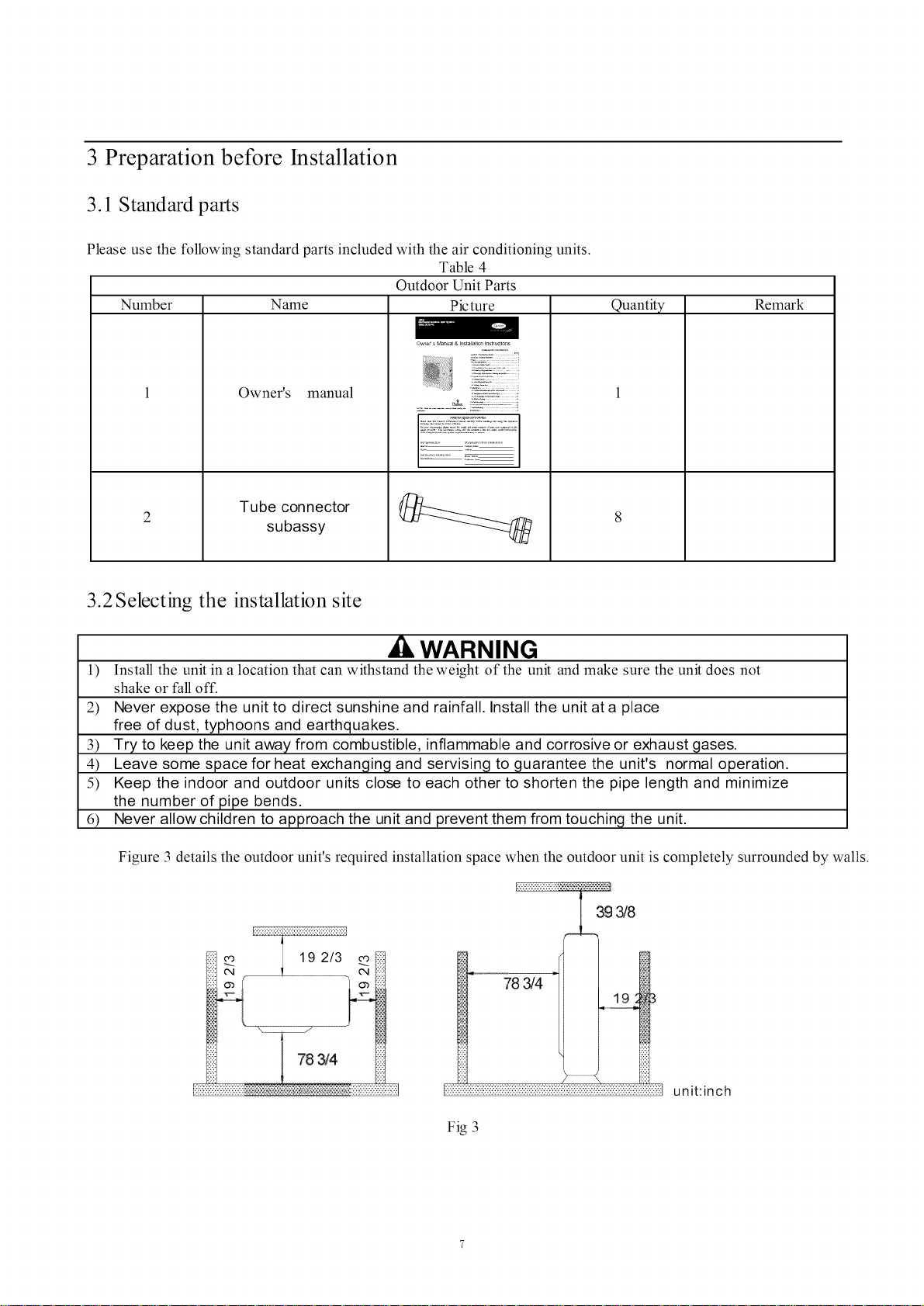
Figure 3 details the outdoor unit's required installation space when the outdoor unit is completely surrounded by walls.
3g 3/8
78 _4
unit:inch
Fig 3
 Loading...