


30GX090
Carrier 30GX090, 30HXA086, 30GX105, 30GX106, 30GX115 Controls, Start-up, Operation, Service, And Troubleshooting
...
Controls, Start-Up, Operation,
Service, and Troubleshooting
SAFETY CONSIDERATIONS
Installing, starting up, and servicing this equipment can
be hazardous due to system pressures, electrical components, and equipment location (roof, elevated structures, etc.).
Only trained, qualified installers and servicemechanicsshould
install, start up, and service this equipment.
When working on this equipment, observe precautions in
the literature, and on tags, stickers, and labels attached to the
equipment, and any other safety precautions that apply. Follow all safety codes. Wear safety glasses and work gloves.
Use care in handling, rigging, and setting this equipment,
and in handling all electrical components.
Electrical shock can cause personal injury and death.
Shut off all power to this equipment during installation
and service. There may be more than one disconnect
switch. Tag all disconnect locations to alert others not
to restore power until work is completed.
This unit uses a microprocessor-based electronic control system. Do not use jumpers or other tools to short
out components, or to bypass or otherwise depart from
recommended procedures. Any short-to-ground of the
control board or accompanying wiring may destroy the
electronic modules or electrical components.
To prevent potential damage to heat exchanger tubes always run fluid through heat exchangers when adding or
removing refrigerant charge.
DO NOT VENT refrigerant relief valves within a building. Outlet from relief valves must be vented outdoors
in accordance with the latest edition of ANSI/ASHRAE
(American National Standards Institute/American Society of Heating, Refrigeration and Air Conditioning Engineers) 15 (Safety Code for Mechanical Refrigeration).
The accumulation of refrigerant in an enclosed space
can displace oxygen and cause asphyxiation. Provide adequate ventilation in enclosed or low overhead areas.
Inhalation of high concentrations of vapor is harmful
and may cause heart irregularities, unconsciousness or
death. Misuse can be fatal. Vapor is heavier than air and
reduces the amount of oxygen available for breathing.
Product causes eye and skin irritation. Decomposition
products are hazardous.
DO NOT attempt to unbraze factory joints when servicing this equipment. Compressor oil is flammable and
there is no way to detect how much oil may be in any
of the refrigerant lines. Cut lines with a tubing cutter as
required when performing service. Use a pan to catch
any oil that may come out of the lines and as a gage for
how much oil to add to system. DO NOT re-use compressor oil.
CONTENTS
Page
SAFETY CONSIDERATIONS ...................1
GENERAL ...................................2
MAJOR SYSTEM COMPONENTS ..............3
Processor Module (PSIO-1) ...................3
DSIO-HV Relay Module .......................3
Electronic Expansion Device Module .........3
Compressor Protection Module (CPM) .........3
PSIO-2 (8052) Module ........................3
Keypad and Display Module
(Also Called HSIO-II) .......................3
Control (LOR) Switch .........................3
OPERATION DATA ..........................3-42
Electronic Expansion Device (EXD) ...........3
• EXV OPERATION
• ECONOMIZER OPERATION
Oil Pumps ...................................4
Motor Cooling ...............................4
Back Pressure Valve (30GX and 30HXA only) ..4
Sensors .....................................4
Compressor Protection Module (CPM) .........4
• OUTPUTS
• INPUTS
Wye-Delta vs Across-the-Line (XL)
Starting Option ............................5
Capacity Control .............................6
• MINUTES LEFT FOR START
• MINUTES OFF TIME
• LOADING SEQUENCE
• CLOSE CONTROL
• LEAD/LAG DETERMINATION
• CAPACITY SEQUENCE DETERMINATION
• MINIMUM LOAD VALVE
• CAPACITY CONTROL OVERRIDES
Head Pressure Control .......................8
• GENERAL
• AIR COOLED UNITS (30GX)
• WATER COOLED UNITS (30HX)
• ADJUSTING PID ROUTINES
Cooler and Condenser (30HXC)
Pump Control .............................10
30GX080-265
30HXA,HXC076-271
ECOLOGIC™ Air-Cooled and Fluid Cooled Chillers
50/60Hz
Manufacturer reserves the right to discontinue, or change at any time, specifications or designs without notice and without incurring obligations.
Book 2
Tab 5c
PC 903 Catalog No. 533-062 Printed in U.S.A. Form 30G,H-3T Pg 1 1-98 Replaces: 30G,H-2T
Series 0,1,2

CONTENTS (cont)
Page
• COOLER PUMP CONTROL
• CONDENSER PUMP CONTROL
Cooler Heater Control .......................13
Keypad and Display Module
(Also Called HSIO-II) ......................13
• ACCESSING FUNCTIONS
AND SUBFUNCTIONS.......................13
• AUTOMATIC DEFAULT DISPLAY.............13
• STATUS FUNCTION .........................16
• TEST FUNCTION ...........................25
• HISTORY FUNCTION........................25
• SET POINT FUNCTION ......................25
• SERVICE FUNCTION ........................30
• SCHEDULE FUNCTION......................37
Temperature Reset ..........................39
• EXTERNAL TEMPERATURE RESET
• EXTERNALLY POWERED RESET
• RETURN FLUID TEMPERATURE RESET
Demand Limit ...............................39
• DEMAND LIMIT
• EXTERNALLY POWERED DEMAND LIMIT
• DEMAND LIMIT (CCN Loadshed Controlled)
TROUBLESHOOTING ......................43-52
Checking Display Codes ....................43
Unit Shutoff ................................43
Complete Unit Stoppage .....................43
Single Circuit Stoppage .....................43
Restart Procedure ...........................43
• POWER FAILURE EXTERNAL TO THE UNIT
Alarms and Alerts ...........................43
Compressor Alarm/Alert Circuit ..............43
EXD Troubleshooting Procedure .............50
• INSPECTING/OPENING ELECTRONIC
EXPANSION VALVES
• INSPECTING/OPENING ECONOMIZERS
SERVICE ..................................52-66
Servicing Coolers and Condensers ..........52
• TUBE PLUGGING
• RETUBING
• TIGHTENING COOLER/CONDENSER
HEAD BOLTS
Inspecting/Cleaning Heat Exchangers ........53
• COOLERS
• CONDENSERS (30HX Only)
Water Treatment ............................53
Condenser Coils (30GX Only) ................53
• COIL CLEANING
Condenser Fans (30GX Only) ................54
Refrigerant Charging/Adding Charge .........54
Oil Charging/Low Oil Recharging ............55
Oil Filter Maintenance .......................56
• REPLACING THE EXTERNAL OIL FILTER
• REPLACING THE INTERNAL OIL FILTER
Compressor Changeout Sequence ...........56
• BURNOUT CLEAN-UP PROCEDURE
Moisture-Liquid Indicator ....................58
Filter Drier ..................................58
Liquid Line Service Valve ....................58
Thermistors ................................58
• LOCATION
• THERMISTOR REPLACEMENT
Pressure Transducers .......................59
• PRESSURE TRANSDUCER CALIBRATION
• TROUBLESHOOTING
Safety Devices ..............................62
• COMPRESSOR PROTECTION
• OIL SEPARATOR HEATERS (30GX)
• COOLER PROTECTION
Relief Devices ..............................62
• PRESSURE RELIEF VALVES
Control Modules ............................64
• PROCESSOR MODULE (PSIO-1), HIGH VOLTAGE
RELAY MODULE (DSIO-HV), AND EXV DRIVER
MODULE (DSIO-EXV), 12/6 MODULE (PSIO-2)
• RED LED
• GREEN LED
Carrier Comfort Network (CCN) Interface .....64
• PROCESSOR MODULE (PSIO-1)
• HIGH VOLTAGE RELAY MODULE (DSIO-HV)
Replacing Defective Processor Module .......66
Winter Shutdown Preparation ................66
PRE-START-UP PROCEDURE ................67
START-UP AND OPERATION .................67
FIELD WIRING ............................68-73
APPENDIX A
(Compressor Must Trip Amps) ...........74-76
APPENDIX B
(Capacity Loading Sequence) ............77-79
APPENDIX C (Available Accessories) .........80
APPENDIX D (CPM Configurations) .........81-85
APPENDIX E (Cooler and
Condenser Pressure Drop) ...............86-88
APPENDIX F
(Typical System Components) ............89,90
INDEX ......................................91
START-UP CHECKLIST ..............CL-1 to CL-8
GENERAL
IMPORTANT: The 30GX/HX units use refrigerant
R-134a. Compressor oil used with R-134a is Polyolester oil.
This publication contains Start-Up, Service, Controls,
Operation and Troubleshooting data for the 30GX080-265
and 30HXA,C076-271 screw chillers.
Circuits are identified as circuits A and B, and compressors are identified as A1 or A2 in circuit A, and B1 in
circuit B.
The 30GX/HX Series chillers feature microprocessorbased electronic controls and electronic expansion devices
(EXD) in each refrigeration circuit.
The control system cycles compressor loaders and/or compressors to maintain the selected leaving fluid temperature
set point. The system automatically positions the EXD to
maintain the specified refrigerant level in the cooler.Thesystem also has capabilities to control a condenser water valve
to maintain suitable leaving-water temperature for the30HXC
unit. Safeties are continuously monitored to prevent the unit
from operating under unsafe conditions. A scheduling function can be programmed by the user to control the unit’s occupied and unoccupied schedules. The control also operates
a test function and a manual control function that allows the
operator to check output signals and ensure components are
operable.
The control system consists of a processor module
(PSIO-1), an EXD driver module (DSIO-EXV), a high voltage relay module on 30GX units (DSIO-HV), 2 six-pack relay boards, a keypad and display module (also called HSIOII), 2 electronic expansion devices (EXDs), 1 compressor
protection module (CPM) per compressor, a PSIO-2 module, 6 thermistors, and 8 transducers. Aremoteenhanceddisplay is available as an accessory.
2

MAJOR SYSTEM COMPONENTS
Processor Module (PSIO-1) —
This module is an
upgrade to the original PSIO (8088) module, with superior
electrical noise immunity capability. It contains the operating software and controls the operation of the machine. It
has 12 input channels and 6 output channels.
The PSIO-1 continuously monitors input/output channel
information received from all the modules and controls all
output signals for all output channels. It also controls the
relays on the six-pack relay board. The processor module
also controls the EXD driver module (as required), commanding it to open or close each EXD in order to maintain
the proper cooler level. Information is transmitted between
the processor module, CPM modules, the EXD driver module, and the HSIO-II standarddisplaymodulethrougha3-wire
communications bus called COMM3. The remote enhanced
display (accessory) is connectedtothePSIO-1modulethrough
a 3-wire communications bus, but uses a different communication bus called COMM1. The COMM1 bus is also used
to communicate to other CCN (Carrier Comfort Network)
devices when the unit is installed in a network application.
DSIO-HV Relay Module — The DSIO-HV module has
4 inputs and 8 outputs and is installed on 30GX units only.
The module communicates the status of the inputs with the
PSIO-1 module and operates the oil heater, outdoor fan, and
minimum load control outputs.
Electronic Expansion Device Module — The elec-
tronic expansion device module has 4 inputs and 2 outputs.
It receives signals from the PSIO-1 module and operates the
electronic expansion devices. The electronic expansion device module also sends the PSIO-1 module the status of its
4 input channels.
CompressorProtectionModule(CPM)— The com-
pressor protection module monitors several of the compressor safeties and controls 4 of the outputs used to control each
compressor. The CPM monitors compressor current, compressor voltage, high pressure switch status, and compressor
motor temperature. The CPM controls the compressor contactors, oil solenoid, and motor cooling solenoid. Each CPM
sends the PSIO-1 its circuit’s motor temperature, alarm status of the module, and the compressor relay status.
PSIO-2 (8052) Module — This module is used as an
input/output module only,as there is no unit software loaded
in the module. This module has 12 input channels and 6 output channels.
Keypad and Display Module (Also Called
HSIO-II) —
This device consists of a keypad with 8 function keys, 4 operative keys, 12 numeric keys, and a 2-line
24-character alphanumeric LCD (liquid crystal display). Key
usage is explained in the Accessing Functions and Subfunctions section on page 13.
Control (LOR) Switch — Control of the chiller is de-
fined by the position of the LOCAL/OFF/REMOTE (LOR)
switch. This is a 3-position manual switch that allows the
chiller to be put under the control of its own controls (LOCAL), manually stopped (OFF), or controlled through a set
of remote contacts (REMOTE). This switch is different than
the switch that is used in the Flotronic™ II controls configuration. The CCN control is enabled through the HSIO-II.
The switch allows unit operation as shown in Table 1.
In the LOCAL position, the chiller is allowed to operate
and respond to the scheduling configuration, CCN configuration, and set point data. In the remote position, the unit
operates similarly to the LOCAL position, except the remote
contacts must be closed for the unit to operate.
Table 1 — Unit Mode from LOR Switch
and CCN State
SWITCH
POSITION
REMOTE
CONTACTS
CCN
CONFIGURATION
CCN
STATE
UNIT
MODE
OFF NR NR NR LOCAL OFF
LOCAL NR
DISABLE NR LOCAL ON
ENABLE
RUN CCN ON
STOP CCN OFF
REMOTE
OPEN NR NR LOCAL OFF
CLOSED
DISABLE NR LOCAL ON
ENABLE
RUN CCN ON
STOP CCN OFF
LEGEND
CCN — Carrier Comfort Network
NR — Input Not Read by Processor
NOTE: Iftheunit is configured for aclock,then the unit isunderclock
control if it is in an ON mode.
OPERATION DATA
Electronic Expansion Device (EXD) —
The microprocessor controls the EXD through the EXD driver module. The EXD will either be an EXV (electronic expansion
valve) or an economizer. Inside both these devices is a linear
actuator stepper motor.
EXV OPERATION — High-pressure liquid refrigerant enters the valve through the bottom. Aseriesof calibrated slots
are located inside the orifice assembly. As refrigerant passes
through the orifice, the pressure drops and the refrigerant
changes to a 2-phase condition (liquid and vapor). To control refrigerant flow for different operating conditions, the
sleeve moves up and down over the orifice, thereby changing orifice size. The sleeve is moved by a linear stepper motor.The stepper motor moves in increments and is controlled
directly by the processor module. As the stepper motor rotates, motion is transferred into linear movement by the lead
screw. Through the stepper motor and lead screw, 1500 discrete steps of motion are obtained. The large number of steps
and long stroke result in very accurate control of refrigerant
flow.
Each circuit has a liquid level sensor mounted vertically
in the top of the cooler shell. The level sensor consists of a
small electric resistance heater and 3 thermistors wired in
series, positioned at different heights inside the body of the
well. The heater is designed so that the thermistors read approximately 200 F (93.3 C) in dry air.Astherefrigerantlevel
rises (falls) in the cooler, the resistance of the closest thermistor(s) will increase (decrease) as it is cooled by the rising
liquid refrigerant (heated by the heater). This large resistance difference allows the control to accurately maintain a
specified level.
The level sensor monitors the refrigerant liquid level in
the cooler and sends this information to the PSIO-1. At initial start-up, the EXV position is at zero.After that, the microprocessor keeps accurate track of the valve position in order
to use this information as input for the other control functions. The processor does this by initializing the EXVs at
start-up. The processor sends out enough closing pulses to
the valve to move it from fully open to fully closed, then
resets the position counter to zero. From this point on, until
the next initialization, the processor counts the total number
of open and closed steps it has sent to each valve.
3

ECONOMIZER OPERATION — Economizers are factory
installed on 30GX105-265 units and 30HXA,C161-271 units.
All other sizes use standard EXVs. The economizer improves both the chiller capacity and efficiency as well as providing compressor motor cooling. Inside the economizer are
both a linear stepper motor (same as standard EXV motor)
and a float valve. The stepper motor is controlled by the processor to maintain the desired liquid level in the cooler (as
is done for chillers without economizers). The float valve
maintains a liquid level in the bottom of the economizer.
Liquid refrigerant is supplied from the condenser through
the end to the bottom of the economizer.Abubbler tube supplies a small amount of discharge gas to ensure that the float
will be able to workproperly. As the refrigerantpassesthrough
the EXD, its pressure is reduced to an intermediate level of
about 75 psig (517 kPag). This pressure is maintained inside
the economizer shell. Next, the refrigerant flows through the
float valve where its pressure is further reduced to slightly
above the pressure in the cooler.
The increase in performance is achieved when some of
the refrigerant passing through the EXD flashes to vapor,
further subcooling the liquid that is maintained at the bottom
of the economizer. This increase in subcooling provides additional capacity. Also, since the additional power required
to accomplish this is minimal, the efficiency of the machine
improves. The vapor that flashes rises to the top of the economizer where it passes to the compressor and is used to provide motor cooling. After passing over the motor windings,
the refrigerant reenters the cycle at an intermediate port in
the compression cycle.
Oil Pumps — The 30GX/HX screw chillers use one ex-
ternally mounted prelubricating oil pump per circuit. This
pump is operated as part of the start-up sequence. On 30GX
units, the pumps are mounted to the base rails on the oil separator side of the unit. The pumps are mounted to a bracket
on the condensers of 30HXC units and to the oil separator
on 30HXA units.
When a circuit is required to start, the controls energize
the oil pump first and read the oil pressure transducer reading. The pump is operated for a period of 20 seconds, after
which the oil solenoid is energized to open the oil inlet valve
at the compressor. The control again reads the pressure from
the oil pressure transducer. If the pump has built up sufficient oil pressure, the compressor is allowed to start.
Once the compressor has started, the oil pump is turned
off within 10 seconds and is not used again until the next
start-up. If the pump is not able to build up enough oil pressure, the pump is turned off. Within 3 seconds, the pump is
re-energized and makes one additional attempt to build oil
pressure. The control generates an alarm if the second attempt fails.
Motor Cooling — Compressor motor winding tempera-
tures are controlled to a set point of 200 F (93.3 C).
The control accomplishes this by cycling the motor cooling
olenoid valve to allow liquid refrigerant to flow across the
motor windings as needed. On units equipped with economizers, flash gas leaves the top of the economizer and continually flows to the motor windings. All refrigerant used for
motor cooling re-enters the rotors through a port located midway along the compression cycle and is compressed to discharge pressure.
Back Pressure Valve (30GX and 30HXA only)
—
This valve is located on the oil separator outlet on 30GX
units and mounted on the oil separator shell of 30HXAunits.
The valve’s function is to ensure that there is sufficient system differential pressure to allow for oil to be driven back to
the compressor. A small copper line (economizer pressure)
is connected to the top of the valve, which contains an internal spring that closes a piston if the pressure in the oil
separator is not at least 15 psig greater than the economizer
pressure.
Sensors — The 30GX,HX control system (based on the
Flotronic™ II chiller control system)gathersinformationfrom
sensors to control the operation of the chiller. The units use
up to 9 standard pressure transducers, 7 standard thermistors
(including 3 motor temperature thermistors), and 2liquidlevel
thermistors to monitor and control system operation. The sensors are listed in Table 2.
Compressor Protection Module (CPM) — Each
compressor has its own CPM. The CPM provides the following functions:
• compressor main contactor control
• Wye-Delta contactor transition
• compressor ground current protection
• motor temperature reading
• high-pressure protection
• reverse rotation protection
• voltage imbalance protection
• current imbalance protection
• compressor oil solenoid control
• motor cooling solenoid control
• sensor bus communications
• starting and running overcurrent protection
The CPM has the following 4 output relays and 4 inputs:
OUTPUTS:
• compressor contactor
• compressor oil solenoid
• compressor motor cooling solenoid
• Wye-Delta transition relay
INPUTS:
• motor temperature
• three-phase voltage
• three-phase current
• high-pressure switch
Adiagram of the CPM board is shown in Fig. 1. There are
line voltage inputs at L1, L2, and L3. Below these inputs are
the current toroid inputs at Plug 1. Below Plug 1 are the 3
COMM3 communication terminals. In the lower left corner
of the board are the inputs for motor winding temperature.
The address DIP (dual-in-line package) switch and compressor must-trip amps header are factory set. For compressor A1, switches 2 and 4 should be set. For compressor A2
(30HXA,C206-271AND 30GX205-265), switches 2, 3, and
4 should be set. For compressor B1, switches 1 and 4 should
be set.
T overifypropermusttripampsheaderconfiguration,press
and use the up arrow key on the HSIO to locate the
must trip amp values. Press the reset button on the HSIO/
fuse panel to update these values. See Appendix A. If the
values do not match those in Appendix A, verify with Appendix D that the configuration headers have been properly
punched out.
4

Table 2 — Thermistor and Transducer Locations
THERMISTORS
Sensor Description Location Connection Terminals
T1 Cooler Leaving Fluid Temp Cooler Head Leaving Fluid Side PSIO-2, J7 pins 2,3
T2 Cooler Entering Fluid Temp Cooler Head Entering Fluid Side PSIO-2, J7 pins 5,6
Motor Temp A1 Motor Temperature A1 Compressor A1 Junction Box CPM-A1, T terminals
Motor Temp A2* Motor Temperature A2 Compressor A2 Junction Box CPM-A2, T terminals
Motor Temp B1 Motor Temperature B1 Compressor B1 Junction Box CPM-B1, T terminals
T5 Discharge Gas TempA Top of Condenser Circuit A (30HXC Only) PSIO-2, J7 pins 8,9
Top of Oil Separator Circuit A (All Other Units)
T6 Discharge Gas Temp B Top of Condenser Circuit B (30HXC Only) PSIO-2, J7 pins 11,12
Top of Oil Separator Circuit B (All Other Units)
LL-A (T3) Liquid Level Circuit A Top of Cooler Circuit A PSIO-1, J7 pins 5,6
LL-B (T4) Liquid Level Circuit B Top of Cooler Circuit B PSIO-1, J7 pins 8,9
T7 (optional)† Outdoor Air Thermistor Outside Air Stream PSIO-2, J7 pins 20,21
STP (optional)† Space Temperature Conditioned Space PSIO-2, J7 pins 23,24
T8 (optional)† Condenser Entering Water Temp Condenser Entering Fluid Line PSIO-2, J7 pins 14,15
T9 (optional)† Condenser Leaving Water Temp Condenser Leaving Fluid Line PSIO-2, J7 pins 17,18
PRESSURE TRANSDUCERS
Sensor Description Location Connection Terminals
DPT-A Discharge Pressure Circuit A Top of Condenser Circuit A (30HXC Only) PSIO-1, J7 pin 22
Top of Oil Separator Circuit A (All Other Units)
SPT-A Suction Pressure Circuit A Top of Cooler Circuit A PSIO-1, J7 pin 19
EPT-A Economizer Pressure Circuit A Economizer Line Entering Comp A PSIO-1, J7 pin 10
OPT-A1 Oil Pressure Compressor A1 Compressor A1 Oil Connection PSIO-1, J7 pin 25
OPT-A2* Oil Pressure Compressor A2 Compressor A2 Oil Connection PSIO-1, J7 Pin 1
DPT-B Discharge Pressure Circuit B Top of Condenser Circuit B (30HXC Only) PSIO-1, J7 pin 16
Top of Oil Separator Circuit B (All Other Units)
SPT-B Suction Pressure Circuit B Top of Cooler Circuit B PSIO-1, J7 pin 31
EPT-B Economizer Pressure Circuit B Economizer Line Entering Comp B PSIO-1, J7 pin 13
OPT-B Oil Pressure Compressor B Compressor B1 Oil Connection PSIO-1, J7 pin 28
*30HX206-271 only.
†Sensors are available as accessories for field installation.
The CPM communicates on the COMM3 communication
bus to the PSIO-1 module. Proper operation of theCPMboard
can be verified by observing the 3 LEDs (light-emitting diodes) located on the board. The top LED is red and blinks
at a rate of once every 1 to 2 seconds. This indicates that the
module is powered and operating correctly.ThemiddleLED
is yellow and blinks when there is an automatic reset alarm
condition. The yellow LED remains on and does not blink
for manual reset alarm conditions. The bottom LED is green
and blinks when the module is satisfactorily communicating
with the PSIO-1 module. The CPM communicates the status
of its inputs and outputs, and reports 18 different alarm conditions to the PSIO-1. The alarms are listed in Table 3.
The CPM module has many features that are specifically designed to protect the compressor, including reverse rotation protection. Do not attempt to bypass or
alter any of the factory wiring. Any compressor operation in the reverse direction will result in a compressor
failure that will require compressor replacement.
The PSIO-1 will generate an alert when it receives an alarm
input from the CPM. The alert will be generated in a y.xx
format, where ‘‘y’’ refers to the compressor and ‘‘xx’’ to the
alarm value in Table 3 (decimal point removed). For example, the HSIO might displayAlarm 1.70 for a voltage phase
reversal occurring on compressor A1. Similarly, the display
would read 5.85 for a motor overtemperature condition on
compressor B1.AlertsforcompressorsA2 and B2 (if present)
would be generated as ‘‘2.xx’’and ‘‘6.xx,’’respectively. Alarm
codes 3 and 4 would not be used. Ending zeros are not
displayed.
The high-pressure switch is wired in series with the relay
coils of the 4 relays on the CPM. If this switch opens during
operation, all relays on the CPM are deenergized and the
compressor is stopped. The failure is reported to the PSIO-1
and the processor module locks off the compressor from restarting until the alarm is manually reset.
Table 3 — Compressor Protection Module
Feedback Codes
ALARM CONDITION VALUE
High Pressure Switch Trip 1.0
No Motor Current 2.0
Current Imbalance Alarm 10% 2.5
Current Imbalance Warning 10% 2.7
Current Imbalance 18% 3.0
Single Phase Current Loss 3.5
High Motor Current 4.0
Ground Fault 5.0
Voltage Imbalance Alarm 3% 5.5
Voltage Imbalance Warning 3% 5.7
Voltage Imbalance 7% 6.0
Voltage Phase Reversal 7.0
Contactor Failure 7.5
Current Phase Reversal 8.0
Motor Overtemperature 8.5
Open Thermistor 9.0
Configuration Header Fault 9.5
Shorted Thermistor 10.0
No Error 0
Wye-Delta vs Across-the-line (XL) Starting
Option —
All 30GX,HX chillers operating at voltages of
208/230-3-60 or 230-3-50 (5 or 8 at Position 12 in model
number) are supplied with factory installed Wye-Deltastarters. All other voltage options can be ordered with either
Wye-Delta or XL starting options. The XL starting method
is the most cost effective and simply starts the compressor
motor in a Delta configuration (the motors are designed for
continuous operation in this configuration) using a single contactor. See Fig. 2. This is the simplest starting method to use
and is ideal where starting current does not require limiting.
5

Where current limitations exist, the Wye-Deltaoptionmay
be used. See Fig. 3. This option uses a factory-installed starter
assembly for each compressor, which consists of 3 contactors labelled 1M, 2M, and S. As the compressor is started,
the CPM module energizes contactors 1M and S, which connects and energizes the motor windings in a Wye configuration. The starting current required will be approximately
60% less than that required for an XL start due to the higher
impedance of the motor windings when Wye connected. The
compressor will attain about 100% of its normal operating
speed (approximately 3 to 6 seconds) before the CPM module deenergizes the S contactor and energizes the 2M contactor, switching the compressor windings to a Delta wiring
configuration. The S and 2M contactors in the starter assembly are both mechanically and electrically interlocked so that
they will not both be energized at the same time.
Do not alter the factory-installed power wiring from the
control box terminal block to the compressor junction block.
Doing so will cause permanent damage to the compressor
and will require that the compressor be replaced.
Capacity Control — The control system cycles com-
pressors, loaders, and minimum load control valves to maintain the user-configured leaving chilled fluid temperature set
point. Entering fluid temperature is used by the microprocessor to determine the temperature drop across the cooler and
is used in determining the optimum time to add or subtract
capacity stages. The chilled fluid temperature set point can
be automatically reset by the return temperature reset or space
and outdoor-air temperature reset features. It can also be reset from an external 4 to 20 mA signal (requires fieldsupplied 500-ohm,1⁄2watt resistor), or from a network signal.
The capacity routine runs every 30 seconds. The routine
attempts to maintain the Control Point at the desired set point.
Each time it runs, the control reads the entering and leaving
fluid temperatures. The control determines the rate at which
conditions are changing and calculates 2 variables based on
these conditions. Next, a capacity ratio (Load/Unload Fac-
tor under ) is calculated using the 2 variables to
determine whether or not to make any changes to the current
stages of capacity. This ratio value ranges from − 100 to
+ 100%. If the next stage of capacity is a compressor, the
control starts (stops) a compressor when the ratio reaches
+ 100% (− 100%). If the next stage of capacity is a loader,
the control energizes (deenergizes) a loader when the ratio
reaches + 60% (− 60%). Loaders are allowed to cycle faster
than compressors, to minimize the number of starts and stops
on each compressor.Adelay of 90 seconds occurs after each
capacity step change.
MINUTES LEFT FOR START — This value is displayed in
the Status subfunction and represents the amount of time to
elapse before the unit is started. This value can be zero without the machine running in many situations. This can include being unoccupied, LOR switch in the OFF position,
CCN not allowing unit to start, Demand Limit in effect, no
call for cooling due to no load, and alarm or alert conditions
present. If the machine should be running and none of the
above are true, a minimum off time may be in effect. The
machine should start normally once the time limit has
expired.
MINUTES OFF TIME ( ) — This user configurable time period is used by the control to determine how
long unit operation is delayed after power is applied/
restored to the unit. It is also used to delay compressor restarts after the unit has shut off its lowest stage of capacity.
Typically, this time period is configured when multiple machines are located on a single site. For example, this gives
the user the ability to prevent all the units from restarting at
once after a power failure. A value of zero for this variable
does not mean that the unit should be running.
LOADING SEQUENCE — The 30GX,HX chiller efficiency is greatest at full load. Therefore, the following sequence list applies to capacity control.
1. Thenextcompressor is not started until all others are running at 100%.
2. The second unloading stage is only used during initial
capacity staging of the unit at start-up.
3. Whenever a compressor is started in a circuit, the loaders
in the circuit are deenergized for 15 seconds before the
compressor is started. The loaders are energized 90 seconds after the compressor is started.
L1
L2
L3
CURRENT TOROID
INPUT PLUG
1
2
3
T
T
TEMPERATURE
ADDRESS DIP
SWITCH
COMM3
24/115/230 VAC
INPUTS/OUTPUTS
COMPRESSOR PROTECTION MODULE (CPM)
COMPRESSOR
MUST TRIP
AMPS HEADER
1
2
RED LED
YELLOW LED
GREEN LED
MOTOR INPUT
PUSH THIS SIDE OF SWITCH
DOWN TO SET ADDRESS
1234
ROCKER DOWN
1
0
2
3
4
5
Fig. 1 — Compressor Protection Module
LED — Light-Emitting Diode
NOTES:
1. The red LED blinks continuously when the module
is operating properly.
2. The yellowLEDblinks during automaticreset alarm,
and is continuously lit when the manual reset alarm
is active.
3. The green LID blinks continuously when communicating properly with PSIO-1.
6

CLOSE CONTROL( ) — When configured for Close
Control, the control is allowed to use any loading/capacity
control devices required to maintain better leaving fluid temperature regulation.Allstagesofunloadingareavailable.See
Appendix B for an example.
LEAD/LAG DETERMINATION ( ) — This is a configurable choice and is factory set to be automatic. The value
can be changed to Circuit A or Circuit B leading, as desired.
Set at automatic, the control will sum the current number of
logged circuit starts and one-quarter (Version 3.0 and later)
of the current operating hours for each circuit. The circuit
with the lowest sum is started first. Changes to which circuit
is the lead circuit and which is the lag are made when shutting off compressors.
On 30HX206-271 and 30GX205-265 units set for staged
loading, the control fully loads the lead circuit before starting the lag circuit and unloads the lag circuit first. When these
units are set for equal loading, the control maintains nearly
equal capacities in each circuit when the chiller is loading
and unloading.
CAPACITY SEQUENCE DETERMINATION ( ) —
This is configurable as equal circuit loading or staged circuit
loading with the default set at staged. The control determines the order in which the steps of capacity for each circuit are changed. This control choice does NOT have any
impact on machines with only 2 compressors.
MINIMUM LOAD VALVE ( ) — When this option
is installed and configured, the first stage of capacity is initiated by energizing the Minimum Load valve relay.The control energizes loaders as needed thereafter. Similarly, the
Minimum Load valve relay will be energized forthelaststage
of capacity to be used before the circuit is shut down.
CAPACITY CONTROLOVERRIDES—The following overrides will modify the normal operation of the routine.
Deadband Multiplier — The user configurableDeadbandMultiplier ( ) has a default value of 1.0. The range is from
1.0 to 4.0. When set to other than 1.0, this factor is applied
to the capacity Load/Unload Factor. The larger this value is
set, the longer the control will delay between adding or removing stages of capacity. Figure 4 shows how compressor
starts can be reduced over time if the leaving water temperature is allowed to drift a larger amount above and below the
set point. This value should be set in the range of 3.0 to 4.0
for systems with small loop volumes.
First Stage Override — If the current capacity stage is zero,
the control will modify the routine with a 1.2 factor on adding the first stage to reduce cycling. This factor is also applied when the control is attempting to remove the last stage
of capacity.
L1
L2
L3
T1
T1
T3
3
2
1
1
2
3
4
6
5
COMPRESSOR JUNCTION BOX
JUMPER BARS
COMPRESSOR CONTACTOR
1
2
3
21
22
23
TERMINAL BLOCK
Fig. 2 — Across-the-Line (XL) Compressor Wiring
1
2
3
4
5
6
1
2
3
T1
T1
T1
T2
T2
T2
T3
T3
T3
S
2M
1M
L3
L3
L3
L2
L2
L2
L1
L1
L1
1
2
3
22
21
23
TERMINAL BLOCK
COMPRESSOR STARTER ASSEMBLY
COMPRESSOR JUNCTION BOX
21
22
23
4
6
5
Fig.3—Wye-Delta Compressor Wiring
7

Slow Change Override —The control prevents the capacity
stages from being changed when the leaving fluid temperature is close to the set point (within an adjustable deadband)
and moving towards the set point.
Ramp Loading ( ) —Limitstherate of change of leaving fluid temperature. If the unit is in a cooling mode and
configured for Ramp Loading, the control makes 2 comparisons before deciding to change stages of capacity. The control calculates a temperature difference between the control
point and leaving fluid temperature. If the differenceisgreater
than 4° F (2.2° C) and the rate of change (°F or °Cperminute)
is less than the configured Cooling Ramp Loading value
( ), the control does not allow any changes to the
current stage of capacity.
Low Entering Fluid Temperature Unloading — When the
entering fluid temperature is below the control point, the control will attempt to remove 25% of the current stages being
used. If exactly 25% cannot be removed, the control removes an amount greater than 25%, but no more than necessary. The lowest stage will not be removed.
Low Discharge Superheat — If a circuit’s discharge superheat is less than 15° F (8.3° C), the control does not increase
the current capacity stage and the EXD is not opened any
further. If the discharge superheat is less than 10° F
(5.6° C) and decreasing, the EXD is closed 50 steps every
10 seconds. If the discharge superheat is less than
5° F (2.8° C) and decreasing, the circuit is unloaded every
30 seconds until the superheat is greater than 5° F
(2.8° C). The final capacity stage is not unloaded unless an
alarm condition exists. This override is ignored for the first
3 minutes after a compressor is started.
Low Saturated Suction Temperature — To avoid freezing
the cooler,thecontrol will compare the circuit Saturated Suction temperature with a predetermined freeze point. For water circuits, the freeze point is 28 F (−2.2 C). For brine circuits, the freeze point is 8° F (4.4° C) below the cooling set
point (lower of 2 cooling set points for dual configuration).
If the saturated suction temperature is below the freeze point,
the unit capacity is not allowed to increase. For brine cir-
cuits, the freeze point can be entered by pressing
and scrolling 12 items down. The control will use the Brine
Freeze Point value less 6°F (3.3°C) as the freeze point to
compare with the Saturated Suction temperature. The default for the Brine Freeze Point is 34 F (1.1 C) which means
the control will use 28 F (−2.2 C) as the freeze point. This
value is adjustable from −15 F to 34 F (−26.1 to 1.1 C). For
water (brine) circuits, if the Saturated Suction temperature
falls below 34 F (1.1 C) (the Brine Freeze Point), the unit
capacity will not increase. If the Saturated Suction temperature falls below 28 F (−2.2 C), the Brine Freeze Point minus
6° F (3.3° C), for 90 seconds, all loaders in the circuit are
turned off. If this condition continues for a total of 3 minutes, the circuit will shut down.
High Condensing Temperature Unloading — Every 10 seconds the control checks for the conditions below. Loaders
will be cycled as needed to control the saturated condensing
temperature below the configured maximum condensing temperature. Configured maximums are 154 F (67.8 C) for30GX,
152 F (66.7 C) for 30HXA, and 122 F (50 C) for 30HXC
units. If a circuit’s saturated condensing temperature is more
than 12° F (6.7 C) below the maximum condensing temperature, the circuit capacity is not allowed to increase. If
the saturated condensing temperature is more than 2° F
(1.1° C) above the maximum condensing temperature for
60 seconds, a loader is turned off. If the saturated condensing
temperature rises to more than 5° F (2.8° C) above the maximum condensing temperature during the 60 seconds, a loader
is turned off immediately. If all the loaders were already off,
the compressor is shut down and an alarm is generated.
MOP(Maximum Operating Pressure) Override —Thecontrol monitors saturated condensing and suction temperature
for each circuit as well as differential oil pressure. Based
on a configurable maximum operating set point (saturated
suction temperature), set maximum condensing temperature, and minimum differential oil pressure, the control may
reduce the number of capacity stages being used and/or may
lower the EXD position when system pressures approach the
set parameters.
Head Pressure Control
GENERAL — The microprocessor controls the condenser
fans (30GX) or analog water valve (30HXC) to maintain the
saturated condensing temperature to a configurable set point.
The fans are staged or speed varied (30GX) or water valve
controlled (30HX) based on each circuit’s saturated condensing temperature and compressorstatus.Water cooled units
(30HXC) operating at less than 70 F (21.1 C) for entering
condenser water require the use of head pressure control.
The chiller must be field configured for the options shown
in Table 4. Fan stage settings are shown in Table 5.
AIR COOLED UNITS (30GX) — See Fig. 5 for condenser
fan locations.
47
46
45
44
43
42
41
0 200 400 600 800 1000
TIME (SECONDS)
2 STARTS
3 STARTS
DEADBAND EXAMPLE
LWT (F)
MODIFIED
DEADBAND
STANDARD
DEADBAND
8
7
6
5
LWT (C)
LEGEND
LWT — Leaving Water
Temperature
Fig. 4 — Deadband Multiplier
8

No Motormastert Control — The fans are controlled based
on Saturated Condensing Temperature. The first fan stage
for each circuit is turnedonwheneverthecompressoristurned
on.Afan stage is added when the Saturated Condensing Temperature (SCT) exceeds the Head Pressure Set Point. The
Head Pressure Set Point is configurable in the Set Point subfunction. The default is 113 F (45 C). Once a fan stage has
been added, the software temporarily modifies the head pressure set point by adding 15° F (8.3° C) for 35 seconds. A
fan stage will be removed when the Saturated Condensing
Temperature has been less than the Head Pressure Set Point
minus 35 F (19.4 C) for 2 minutes.Thecontrolusesthehigher
of the 2 Saturated Condensing Temperature values for
30GX080-150 and 160 units. For the 30GX151 and 161-265
units, each circuit’s fan stages are independently controlled
based on the circuit Saturated Condensing Temperature.
Refer to Table 6 for condenser fan control information. See
Fig. 6A.
With Motormaster Control — For low-ambient operation,
the lead fan in each circuit can be equipped with the optional
or accessory Motormaster III head pressure controller. This
controller can be used in one of 2 ways. If factory installed,
the controller will be configured for 4 to 20 mA control. With
the Motormaster III option enabled, the PSIO-1 module calculates the required output based on Saturated Condensing
temperature, Head Pressure set point, and a PID (proportional integral derivative) loop calculation. This 4 to
20 mA output is driven through the PSIO-2 module. To obtain this accessory for field installation, order by part number 30GX-900---012forasinglecontroller package (30GX080150 and 160). Order part number 30GX-900---014 for a
dual controller package (30GX151 and 161-265). These
packages contain all the hardware required to install the
accessory. See Fig. 6B.
The control will use the higher of the 2 Saturated Condensing Temperature values for 30GX080-150 and 160 units.
For the 30GX151 and 161-265 units, each circuit’s fan stages
are independently controlled based on the circuit Saturated
Condensing Temperature. Refer to Table6 for condenser fan
staging information.
WATER-COOLED UNITS (30HX) — The 30HX chillers
can be configured to control direct or reverse-acting water
valves that are controlled bya4to20mAsignal. A 2 to
10 VDC signal can be used by installing a 500-ohm resistor
across the 2 output terminals of the 4 to 20 mA signal. This
control scheme reads the saturated condensing temperature
and uses a PID (proportional integral deriative) loop to
control the head pressure. Proportional, Integral and Derivative gain parameters for both the water and air cooled controls are adjustable and can be found in the Service subfunction. Checkout and adjustment of the PID loop should
only be performed by certified Carrier Comfort Network
technicians.
Table 4 — Field Configured Chiller Options
CONFIGURATION OPTION DESCRIPTION HSIO LOCATION FACTORY CONFIGURED?
Fan Staging Select Air cooled staging method
Yes. See Table 5
Motormaster Control Select Applies to air cooled units only
Yes. 0 = None
Set to 1 to enable (Motormaster only)
Water Valve Type Applies to water cooled unit only
Yes. 0 = None
Setto1=4−20mA,2=0−10V,
3=20−4mA,4=10−0V
Table 5 — Fan Staging Settings for Air Cooled (30GX) Units
UNIT 30GX DESCRIPTION OPTION NUMBER
080-105
1st stage compressor status
2nd stage common control based on highest SCT
12
106-125
1st stage compressor status
2nd and 3rd stage common control based on highest SCT
14
136, 150, 160
1st stage compressor status
2nd through 4th stage common control based on highest SCT
16
151, 161, 175,
205, 225
1st stage each circuit, compressor status
2nd stage Circuit B independent
2nd and 3rd stage Circuit A independent
7
176
1st stage each circuit, compressor status
2nd and 3rd stage each circuit independent
3
206, 226, 250
1st stage each circuit, compressor status
2nd stage Circuit B independent
2nd, 3rd and 4th stage Circuit A independent
9
251, 265
1st stage each circuit, compressor status
2nd, 3rd and 4th stage each circuit independent
5
LEGEND
SCT — Saturated Condensing Temperature
9

ADJUSTING PID ROUTINES — The 30GX and 30HXC
head pressure control routines use PID (proportional integral derivative) loops to maintain a user-configurable head
pressure set point. Gain default values are located in the Service function. See page 30. The current values can be read
under from the HSIO. The control calculates a new
fan speed (30GX) or water valve position (30HXC) every
5 seconds based on these gain values and an error term equal
to saturated condensing temperature minus head pressure set
point. If the control routine is not responding fast enough to
large changes (circuit starting, for example), increase the proportional term.
When the routine is making too great a change to valve
position or fan speed, decrease the proportional term.To minimize hunting, keep the integral term positive and as low as
possible. The default for the derivative term is zero. This
valve is used to control ‘‘droop,’’which is common in master/
submaster control schemes. The value should not need to be
changed.
Cooler and Condenser (30HXC) Pump Control
—
The 30GX and 30HX chillers can be configured forcooler
and condenser (30HXC) pump control. Inputs for a cooler
flow switch or interlock and condenser flow switch are also
provided.
COOLER PUMP CONTROL ( ) — The factory default setting for cooler pump control is ‘‘Not Controlled.’’
All chillers are enabled at the factory for cooler pump interlock. See page 71 of Field Wiring section for wiring of
cooler flow switch and/or cooler pump interlock contacts.
Whether cooler pump control is enabled or not, the control
generates an alarm if this input does not close within one
minute after the unit switches to an occupied mode or the
cooler pump is turned on. See Alarms and Alerts section,
page 43 for a description of Alarms 53-55. If cooler pump
control is enabled, the control waits one minute and checks
the interlock or switch input before starting to determine if
cooling is needed. The cooler pump is turned on when the
chiller is in the occupied mode and turned offotherwise.The
cooler pump is turned on in either of two override conditions: If the cooler freeze protection alarm has been generated, the cooler pump is turned on if not already running. If
a cooler heater is being used and has been on for more than
15 minutes during saturated suction freeze protection, the
cooler pump is turned on.
1
2
3
4
CONTROL
BOX
END
5
6
7
8
9
10
CONTROL
BOX
END
4
2
1
3
CONTROL
BOX
END
13 5 7
24 6 8
CONTROL
BOX
END
4
6
1
3
5
2
5
CONTROL
BOX
END
7911
12
6810
4
2
3
1
CONTROL
BOX
END
1
3
5
7
2
4
6
8
CONTROL
BOX
END
14
12
10
13
11
9
1
3
5
7
2
4
6
8
9
11
12
10
Fig. 5 — 30GX Condenser Fan Locations
30GX080-105 30GX106-125
30GX151, 161, 175, 205, 225 30GX176
30GX206, 226, 250
30GX136, 150, 160
30GX251, 265
10

Table 6 — 30GX080-265 Condenser Fan Staging (PSIO-1 Controlled)
30GX UNIT SIZE FAN TYPE FAN CONTACTOR FANS CONTROLLED FAN RELAY NO.*
080-105
Standard
FC-1 1, 2 5
FC-2 3, 4 1
High Static
FC-1, 1A 1, 2 5
FC-2, 2A 3, 4 1
106-125
Standard
FC-1 1, 2 5
FC-2 3, 4 1
FC-3 5, 6 2
High Static
FC-1, 1A 1, 2 5
FC-2, 2A 3, 4 1
FC-3, 3A 5, 6 2
136, 150,
160
Standard
FC-1 1, 2 5
FC-2 3, 4 1
FC-3 5, 6 2
FC-4 7, 8 2
High Static
FC-1, 1A 1, 2 5
FC-2, 2A 3, 4 1
FC-3, 3A 5, 6 2
FC-4, 4A 7, 8 2
151, 161, 175
205, 225
Standard
FC-1 1, 2 Comp. B1 contactor†
FC-2 3, 4 3
FC-3 5, 6 2
FC-4 7, 8 Comp. A1/A2 contactor†
FC-5 9, 10 1
High Static
FC-1, 1A 1, 2 Comp. B1 contactor†
FC-2, 2A 3, 4 3
FC-3, 3A 5, 6 2
FC-4, 4A 7, 8 Comp. A1/A2 contactor†
FC-5, 5A 9, 10 1
176
Standard
FC-1 1, 2 Comp. B1 contactor†
FC-2 3, 4 3
FC-3 5, 6 4
FC-4 7, 8 Comp. A1 contactor†
FC-5 9, 10 1
FC-6 11, 12 2
High Static
FC-1, 1A 1, 2 Comp. B1 contactor†
FC-2, 2A 3, 4 3
FC-3, 3A 5, 6 4
FC-4, 4A 7, 8 Comp. A1 contactor†
FC-5, 5A 9, 10 1
FC-6, 6A 11, 12 2
206, 226, 250
Standard
FC-1 1, 2 Comp. B1 contactor†
FC-2 3, 4 3
FC-3 5, 6 1
FC-4 7, 8 Comp. A1/A2 contactor†
FC-5 9, 10 2
FC-6 11, 12 2
High Static
FC-1, 1A 1, 2 Comp. B1 contactor†
FC-2, 2A 3, 4 3
FC-3, 3A 5, 6 1
FC-4, 4A 7, 8 Comp. A1/A2 contactor†
FC-5, 5A 9, 10 2
FC-6, 6A 11, 12 2
251, 265
Standard
FC-1 2, 4 1
FC-2 6, 8 2
FC-3 1 Comp B1 contactor†
FC-4 3 3
FC-5 5, 7 4
FC-6 9, 10 Comp. A1/A2 contactor†
FC-7 11, 12 2
FC-8 13, 14 2
High Static
FC-1, 1A 2, 4 1
FC-2, 2A 6, 8 2
FC-3 1 Comp. B1 contactor†
FC-4 3 3
FC-5, 5A 5, 7 4
FC-6, 6A 9, 10 Comp. A1/A2 contactor†
FC-7, 7A 11, 12 2
FC-8, 8A 13, 14 2
LEGEND
Comp. — Compressor
FC — Fan Contactor
*Fan Relay number displayed when using to test fans.
†Proper rotationof these fans tobe checked whencompressor(s) is running.SeeFig. 5 forcondenser fan locationswhen viewing
from the control box end.
11

CONDENSER PUMP CONTROL ( ) — Factory defaults for both condenser pump control and condenser flow
switch are set to ‘‘Not Controlled’’and ‘‘Disabled,’’ respectively. The condenser pump can be controlled in one of two
ways: In the first method, the pump can be controlled like
the cooler pump — it is turned on whenever the machine is
in the on state and turned off otherwise (set to Type 1 using
the Service function). The second method of control is to
turn the pump on when the first compressor is started and off
when the last compressor is turned off (set to Type 2 using
the Service function). With the flow switched enabled, the
control checks the status of the input one minute after starting the pump. An alarm is generated if the flow switch input
is not closed.
READ CIRCUIT
SATURATED
CONDENSING
TEMPERATURE
AND CURRENT
FAN STAGE
IS SCT GREATER
THAN HEAD
PRESSURE
SET POINT?
INCREASE
CURRENT FAN
STAGE BY ONE
ADD 15° F TO
HEAD PRESSURE
SET POINT FOR
NEXT 35 SECONDS
DECREASE
CURRENT FAN
STAGE BY ONE
HAS SCT BEEN 35° F
LESS THAN HEAD
PRESSURE SET POINT
2 MINUTES?
NO
NO
YES
YES
LEGEND
SCT — Saturated Condensing Temperature
Fig. 6A — 30GX Head Pressure Control Without MotormasterT III Control
30GX UNITS — MOTORMASTER III CONTROL NOT INSTALLED
30GX UNITS — MOTORMASTER III CONTROL INSTALLED
DECREASE
CURRENT FAN
STAGE BY ONE
NO
NO
YES
IS SCT GREATER
THAN HEAD
PRESSURE SET
POINT PLUS 15F?
INCREASE
CURRENT FAN
STAGE BY ONE
YES
READ CIRCUIT
SATURATED
CONDENSING
TEMPERATURE
AND CURRENT
FAN STAGE
NO
INCREASE
CURRENT FAN
STAGE BY ONE
YES
CALCULATE NEW
PID VALUE. DOSE
OUTPUT REQUIRE
MORE FANS?
OUTPUT NEW mA
SIGNAL TO
CONTROLLER
DOES PID OUTPUT
REQUIRE LESS
FANS?
LEGEND
PID — Proportional Integral Derivative
SCT — Saturated Condensing Temperature
Fig. 6B — 30GX Head Pressure Control With Motormaster III Control
12
Cooler Heater Control — Accessory cooler heaters
can be ordered for the 30GX chillers. If installed and enabled, these heaters are turned on only when the machine is
in the off state and the chiller is in a saturated suction temperature freeze condition.
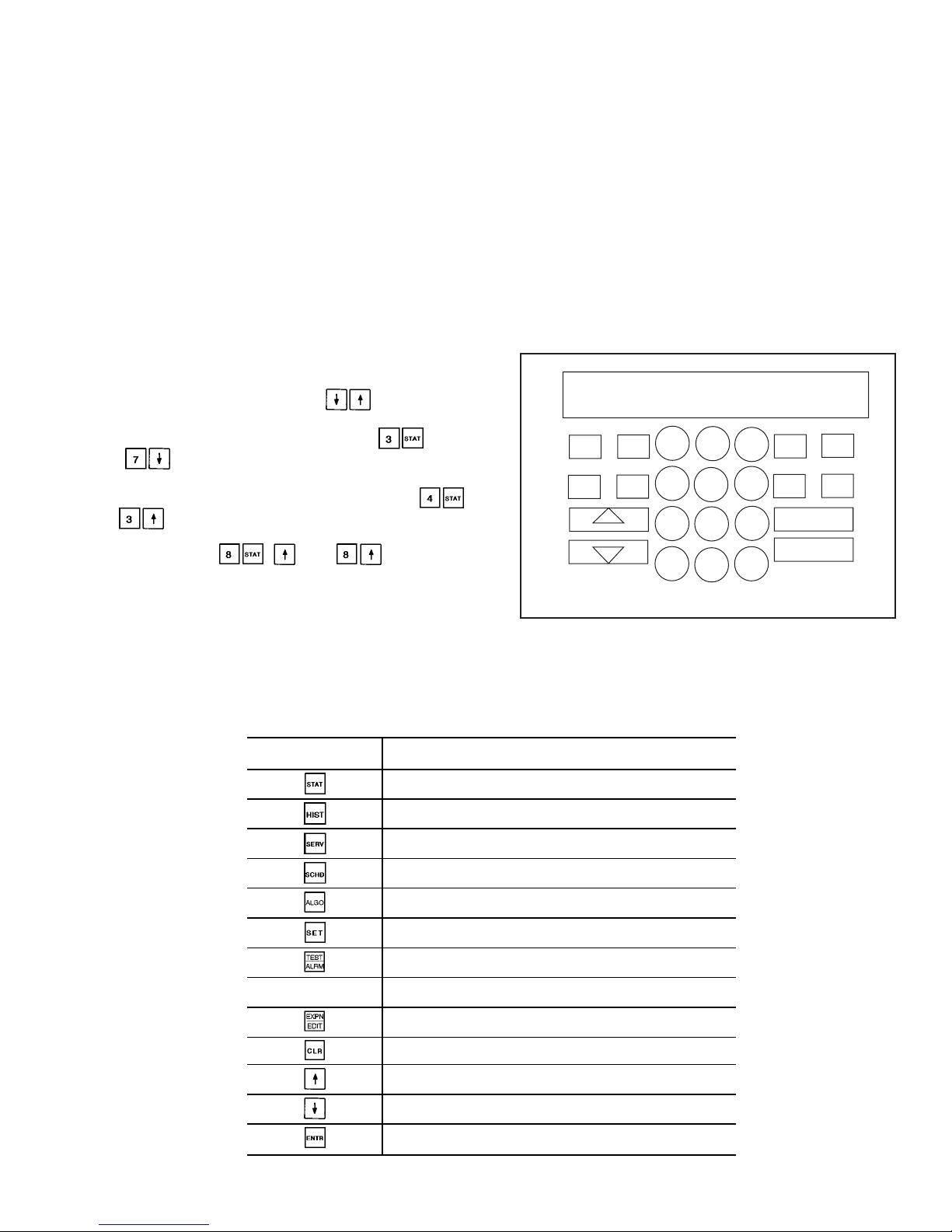
Keypad and Display Module (Also Called
HSIO-II) —
This module allows the operator to communicate with the processor. It is used to enter configurations
and set points and to read data, perform tests, and set schedules. The device consists of a keypad with 7 function keys,
5 operative keys, 12 numeric keys (0 to 9, •, and -), and a
2-line, 24-character alphanumeric liquid crystal display. See
Fig. 7.
ACCESSING FUNCTIONS AND SUBFUNCTIONS —
Table 7 shows a brief description of the keypad buttons.
Table 8A shows the 6 functions (identified by name) and the
subfunctions (identified by number). Table 8B shows the 6
functions (identified by name) and the subfunctions (identified by number) when using the optional LID-2B controller. Table 9 shows a brief example on how to access
subfunctions.
NOTE: It is not necessary to use the through every
item in a subfunction. For example, if you wanted to read
the oil pressure for the A1 compressor, press , then
press to go directly to A1 Oil Pressure. Use a simi-
lar procedure to view an item near the bottom of a subfunction. To view the Circuit A Oil Switch status, press
and . Use a similar procedure to view an item near
the bottom of a subfunction. Toview Condenser Pump Flow
Switch status, press , , and . This proce-
dure is available in all functions except the TEST function.
AUTOMATIC DEFAULT DISPLAY — When the keypad
has not been used for 10 minutes, the display automatically
switches to the rotating automatic default display. This display contains the 5 parts shown below.
Entering Fluid Temp
xx.x° F
Leaving Fluid Temp
xx.x° F
Percent Total Capacity
xxx.x%
Total Number of Alarms
xx
MODES : MODE_TBL
Current active modes
All functions are made up of a group of subfunctions. To
enter a subfunction, first press the subfunction number desired. Then press the function key in which the subfunction
resides. To move within that subfunction, press the up or
down arrow keys. Another subfunction may be entered at
any time by pressing the subfunction number, then the function key. Depending on system type and configuration, all
displays may not be shown.
Table 7 — Keypad and Display Module Usage
FUNCTION
KEYS
USE
STATUS — For displaying diagnostic codes and
current operating information about the machine.
HISTORY — For displaying run time, cycles, and
previous alarms.
SERVICE — For entering specific unit configuration
information and enabling manual control function.
SCHEDULE — For entering occupied/unoccupied
schedules for unit operation.
ALGORITHM — Not used.
SET POINT — For entering operating set points
and day/time information.
TEST — For testing operating of the analog and
discrete outputs.
OPERATIVE
KEYS
USE
EXPAND — For displaying a non-abbreviated
expansion of the display.
CLEAR — For clearing the screen of all displays.
UP ARROW — For returning to previous display
position.
DOWN ARROW — For advancing to next display
position.
ENTER — For entering data.
CLEAR
ENTER
1
2
3
4
5
6
7
8
9
0
.
-
STAT
SET
SCHD
EXPN
EDIT
SRVC
HIST
ALGO
TEST
ALRM
TWENTY-FOUR CHARACTER
TWO-LINE LCD DISPLAY
LEGEND
LCD — Liquid Crystal Display
Fig. 7 — Keypad and Display Module
13

Table 8A — HSIO Functions and Subfunctions
SUBFUNCTION
NO.
FUNCTIONS
Status
Test Schedule Service History Set Point
1
Alarm
Display
Circuit A
Discrete Outputs
Ice Build
Occupancy
Schedule
Factory
Configuration
Operating Hours Set Points
2
General Parameters
Display
Circuit B
Discrete Outputs
Local/Normal
Occupancy
Schedule
Options
Configuration 1
Alarm History English/Metric
3
Circuit A
Analog Values
Unit
Discrete Outputs
Remote CCN
Occupancy
Schedule
Options
Configuration 2
— Bus Address
4
Circuit A
Discrete Inputs/
Outputs Table
Valves and
MotormasterT
Control
Holiday 01
Configuration
Reset/Demand Limit
Configuration
— Time/Date
Configuration
5
Circuit B
Analog Values
— Holiday 02
Configuration
Machine
Configuration
Codes
— CCN
Enable/Disable
6
Circuit B
Discrete Inputs/
Outputs Table
— Holiday 03
Configuration
———
7
Unit Analog
Parameters
— Holiday 04
Configuration
Transducer
Calibration
——
8
Miscellaneous
Inputs/Outputs
— Holiday 05
Configuration
Manual Control — —
9
Operating Modes — Holiday 06
Configuration
Master/Slave
Configuration
——
10
Capacity Control — Holiday 07
Configuration
———
11
Dual Chiller — Holiday 08
Configuration*
———
*Subfunctions through are for configuring Holidays 09 through 30.
14

Table 8B — Functions and Subfunctions Cross-Reference for the Optional LID-2B Controller
The optional LID-2B controller cross reference table below can be used as a guide to access the same information
outlined in the HSIO functions and subfunctions table (see
Table 8A). For example, in Table 8A, the alarm history is
accessed through the HSIO by pressing 2 and the History
button on the keypad (see Table 7). The LID-2B cross
reference table lists the menu item from the LID-2B which
contains the alarm history information. In another example,
from Table 8A, pressing 3 and the Status button on the HSIO
keypad will access the circuit A analog values. In the table
below, the circuit A analog values are accessed by selecting
STATUS CIRCA_AN from the appropriate LID-2B menu.
HSIO
SUBFUNCTION
NO.
HSIO FUNCTION KEY
Status
Test Schedule Service History Set Point
1
STATUS
A_UNIT_1
SERVICE
CONTROL TEST
SCHEDULE
OCCPC012
SERVICE
EQUIPMENT
CONFIGURATION
SERVICE
EQUIPMENT
CONFIGURATION
STRTHOUR
SETPOINT
2
STATUS
A_UNIT_1
SERVICE
CONTROL TEST
SCHEDULE
OCCPC02S
SERVICE
EQUIPMENT
CONFIGURATION
OPTIONS1
SERVICE
ALARM HISTORY
SERVICE
LID
CONFIGURATION
3
STATUS
CIRCA_AN
SERVICE
CONTROL TEST
SCHEDULE
OCCPC65S
SERVICE
EQUIPMENT
CONFIGURATION
OPTIONS2
—
SERVICE
CONTROLLER
IDENTIFICATION
4
STATUS
CIRA_DIO
SERVICE
CONTROL TEST
SERVICE
EQUIPMENT
CONFIGURATION
HOLIDAY,HOLDY_01
SERVICE
EQUIPMENT
CONFIGURATION
RESETCON
—
SERVICE
TIME AND DATE
5
STATUS
CIRCB_AN
—
SERVICE
EQUIPMENT
CONFIGURATION
HOLIDAY,HOLDY_02
SERVICE
EQUIPMENT
CONFIGURATION
CONCODES
—
STATUS
A_UNIT_1
6
STATUS
CIRB_DIO
—
SERVICE
EQUIPMENT
CONFIGURATION
HOLIDAY,HOLDY_03
———
7
STATUS
UNIT_2
—
SERVICE
EQUIPMENT
CONFIGURATION
HOLIDAY,HOLDY_04
SERVICE
EQUIPMENT SERVICE
CALIBRTE
——
8
STATUS
UNIT_3
—
SERVICE
EQUIPMENT
CONFIGURATION
HOLIDAY,HOLDY_05
SERVICE
EQUIPMENT SERVICE
MAN_CTRL
——
9
STATUS
MODE_TBL
—
SERVICE
EQUIPMENT
CONFIGURATION
HOLIDAY,HOLDY_06
SERVICE
EQUIPMENT
CONFIGURATION
MSTR_SLV
——
10
SERVICE
CONTROL
ALGORITHM
STATUS
LOADFACT
—
SERVICE
EQUIPMENT
CONFIGURATION
HOLIDAY,HOLDY_07
———
11
SERVICE
CONTROL
ALGORITHM
STATUS
LEADLAG
—
SERVICE
EQUIPMENT
CONFIGURATION
HOLIDAY,HOLDY_08*
——
—
*Subfunctions through are for configuring Holidays 09 through 30, and are also found under Service, Equipment
Configuration.
NOTE: The optional LID-2B controller uses the same password (1111) as the HSIO.
15

Table 9 — Accessing Functions and Subfunctions
OPERATION KEYPAD ENTRY DISPLAY RESPONSE
To access a function, press
subfunction no. and function
name key. Display shows subfunction group.
Circuit A Discrete Outputs
Loader A1
Relay is OFF
To move to other elements,
scroll up or down using arrow keys.
Loader A2
Relay is OFF
Minimum Load Valve A
Relay is OFF
Circuit A Oil Heater
Relay is OFF
A1 Mtr. Cooling Solenoid
Relay is OFF
A2 Mtr. Cooling Solenoid
Relay is OFF
Circuit A Oil Pump
Relay is OFF
Oil Solenoid A1
Relay is OFF
Oil Solenoid A2
Relay is OFF
When the last element in a
subfunction has been displayed,
the first element is repeated.
Loader A1
Relay is OFF
To move to next subfunction
it is not necessary to use
subfunction number. Press
function name key to
advance display through all
subfunctions within a
function and then back
to the first.
Circuit B Discrete Outputs
Loader B1
Relay is OFF
Unit Discrete Outputs
Valves and Motor Master
Circuit A Discrete Outputs
To move to another function,
either depress function name
key for desired function
(display shows the first
subfunction),
or
Access a specific subfunction by using the subfunction number and the
function name key.
Alarms : xx
Reset Alarms : 1 <ENTER>
CIR. A DISCRETE OUTPUTS
STATUS FUNCTION — This function shows the rotating
display, current status of alarm and alert (diagnostic) codes,
capacity stages, operating modes, chilled water set point, all
measured system temperatures and pressures, analog inputs,
and switch inputs. Refer to Table 10 for a complete description of the function.
Alarms/Alerts — Alarms and alerts are messages that one
or more faults have been detected. The alarms and alerts indicate failures that cause the unit to shut down, terminate an
option (such as reset) or result in the use of a default value
such as a set point. Refer to the Troubleshooting section for
more information.
Up to 10 alarms/alerts can be stored at once. Toviewthem,
press . The control will display the current total
number of alarms/alerts. Use the arrow keys to scroll through
the list. Press the key when needed to view the full
description of an alarm or alert. Press to clear
all the alarms. See Table 11.
IMPORTANT: Do not clear the alarms without first
reviewing the full list and investigating and correcting
the cause of the alarms.
When an alarm or alert is stored in the display and the
machine automatically resets, the alarm/alert is deleted. Codes
for safeties which do not automatically reset are not deleted
until the problem is corrected and the machine is reset. To
clear manual reset alarms from the CPM modules, the reset
button on the HSIO bracket must be pressed. Next, switch
the LOR switch to OFF and back to Local or Remote
position (default alarm clearing method). Press
and then to clear the alarm from the PSIO
if the default LOR reset function has been disabled.
General Parameters — General operating parameters are
displayed including control mode, run status, CCN status,
and the 5 most current alarms. Press to display these
and the other values as shown in Table 10.
CircuitAand B Analog and Discrete Information —Circuit
A Analog Values can be viewed bypressing and scrolling down to see current system operating conditions such as
pressures and temperatures. Pressing will bring up
Circuit A Discrete Inputs and Outputs. Scroll down to view
the On/Off status of the compressor(s), loaders, solenoids,
and pumps. Oil switch and feedback inputs are also dis-
played. Press and to view the identical analog values and discrete inputs and outputs for Circuit B. See
Table 10 for a complete display.
16

Unit Analog Parameters and Temperature Reset — Press
and scroll down to display the unit entering and leav-
ing fluid temperatures as well as the temperature reset signal
and calculated values.
Miscellaneous Inputs and Outputs — Pressing and
scrolling down will reveal the On/Off status of the con-
denser fans (30GX only). Also found here are the Demand
Limit settings, pump relay and switch status, and miscellaneous items such as Heat/Cool and Dual Set Point switch
positions. See Table 10 for a complete list.
Modes —Theoperatingmodesaredisplayed to indicate the
operating status of the unit at a given time. See Table 12 for
a complete list of all modes.
To enter the MODES subfunction, press and use
the key to view all current modes of operation. See
Table 13.
Capacity Control — Pressing , this subfunction displays the load/unload factor, control point, and leav-
ing water temperature. Scrolling down will also reveal the
liquid level sensor values in degrees format.
Dual Chiller — Pressing will access the dual
chiller control status. This subfunction will display whether
or not the chiller is operating as a Master or Slave, any alarm
conditions present for dual chiller control, and lead/lag information for changeover. Dual chiller control is configured
under .
17
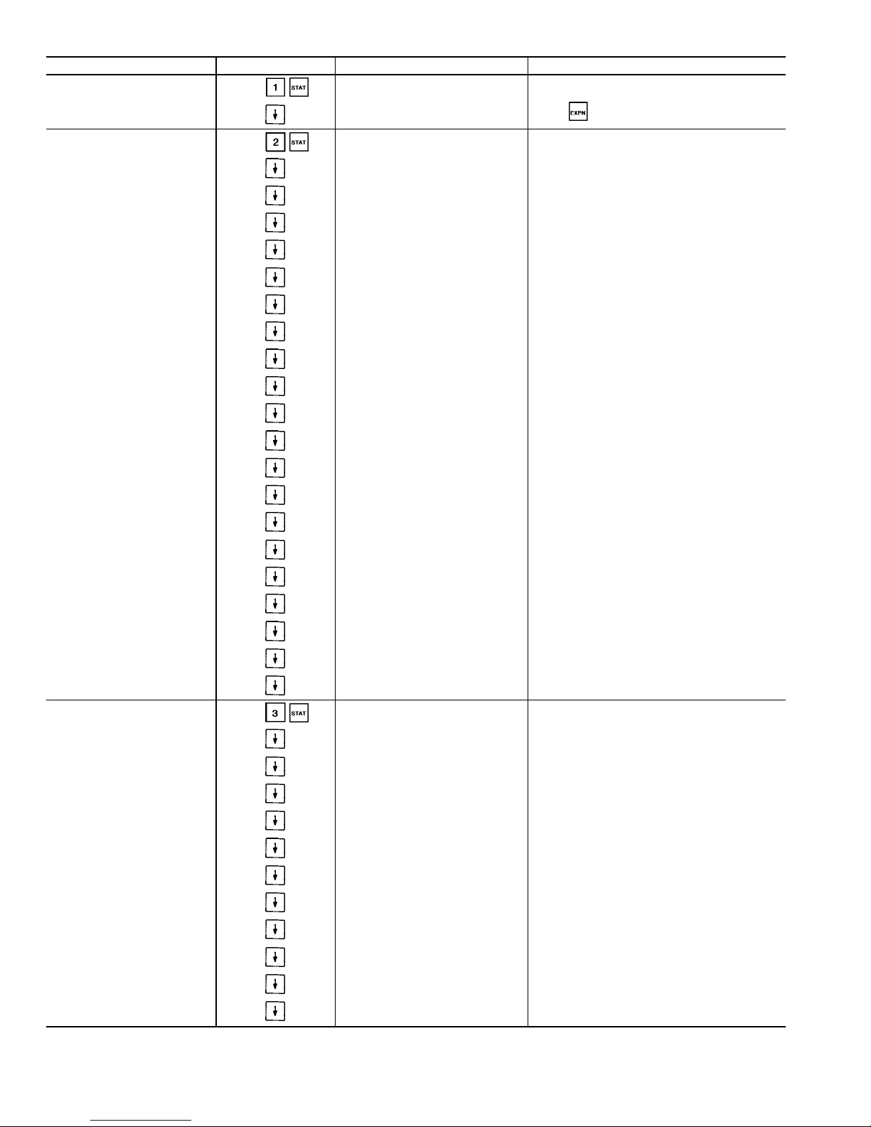
Table 10 — Status Function and Subfunction Directory
SUBFUNCTION KEYPAD ENTRY DISPLAY COMMENT
1 Alarms
Alarm : xx
Reset Alarms: 1 <ENTER>
All current alarms are displayed Use as needed
2 General Parameters GENERAL PARAMETERS
Displays LOCAL ON/OFF or CCN ON/OFF
Force/clear value with HSIO or CCN device.
Must be ON for CCN clock control.
Control Mode
Run Status
Off/On
Occupied ?
Yes/No
CCN Enable
Off/On
CCN Chiller Start/Stop
Start/Stop
Alarm State
Normal/Alarm
Current Alarm 1
x.xx
Current Alarm 2
x.xx
Current Alarm 3
x.xx
Current Alarm 4
x.xx
Current Alarm 5
x.xx
Active Demand Limit
xxx.x%
Percent Total Capacity
xxx.x%
Water/Brine Setpoint
xx.x dF
Control Point
xx.x dF
Entering Fluid Temperature
xx.x dF
Leaving Fluid Temperature
xx.x dF
Emergency Stop
Emstop
Minutes Left for Start
xx min
Heat-Cool Status
Heat/Cool
3 Circuit A Analog Values
CIRCUIT A ANALOG VALUES
Percentage of total circuit capacity
currently in use.
Percentage of Total Capacity value not in
an alarm or fault condition.
Total Capacity
xxx.x%
Available Capacity
xxx.x%
Discharge Pressure
xxx.x PSI
Suction Pressure
xxx.x PSI
A1 Oil Pressure Diff.
xxx.x PSI
A2 Oil Pressure Diff.
xxx.x PSI
A1 Oil Pressure
xxx.x PSI
A2 Oil Pressure
xxx.x PSI
Discharge Gas Temperature
xxx.x dF
A1 Motor Temperature
xxx.x dF
A2 Motor Temperature
xxx.x dF
See Legend on page 23.
18

Table 10 — Status Function and Subfunction Directory (cont)
SUBFUNCTION KEYPAD ENTRY DISPLAY COMMENT
3 Circuit A Analog Valves (cont)
SAT Condensing Temp
xxx.x dF
Saturated Suction Temp
xxx.x dF
EXV Percent Open
xxx.x%
Motormaster Speed
xxx.x%
Water Valve Position
xxx.x%
Cooler Level Indicator
x.xx
CPM A1 Feedback
x.x Volts
See Table 3.
CPM A2 Feedback
x.x Volts
See Table 3.
Circuit A Econ Pressure
xxx.x PSI
4 Circuit A Discrete Inputs/Outputs
CIR. A DISCRETE OUTPUTS
Compressor A1
Off/On
Compressor A2
Off/On
Loader A1
Off/On
Loader A2
Off/On
Minimum Load Valve A
Off/On
Circuit A Oil Heater
Off/On
A1 Mtr Cooling Solenoid
Off/On
A2 Mtr Cooling Solenoid
Off/On
Circuit A Oil Pump
Off/On
Oil Solenoid A1
Off/On
Oil Solenoid A2
Off/On
CIR. A DISCRETE INPUTS
Circuit A Oil Switch
Open/Close
Compressor A1 Feedback
Off/On
Compressor A2 Feedback
Off/On
5 Circuit B Analog Values
CIRCUIT B ANALOG VALUES
Percentage of total circuit capacity
currently in use.
Percentage of Total Capacity value
not in an alarm or fault condition.
Total Capacity
xxx.x%
Available Capacity
xxx.x%
Discharge Pressure
xxx.x PSI
Suction Pressure
xxx.x PSI
B1 Oil Pressure Diff.
xxx.x PSI
B2 Oil Pressure Diff.
xxx.x PSI
B1 Oil Pressure
xxx.x PSI
B2 Oil Pressure
xxx.x PSI
Discharge Gas Temperature
xxx.x dF
19
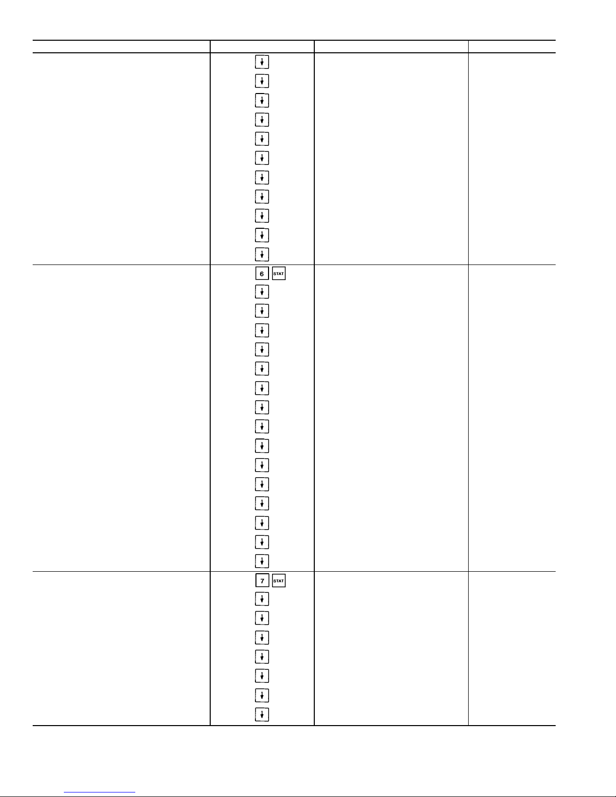
Table 10 — Status Function and Subfunction Directory (cont)
SUBFUNCTION KEYPAD ENTRY DISPLAY COMMENT
5 Circut B Analog Valves (cont)
B1 Motor Temperature
xxx.x dF
B2 Motor Temperature
xxx.x dF
SAT Condensing Temp
xxx.x dF
Saturated Suction Temp
xxx.x dF
EXV Percent Open
xxx.x%
Motormaster Speed
xxx.x%
Water Valve Position
xxx.x%
Cooler Level Indicator
x.xx
CPM B1 Feedback
x.x Volts
See Table 3.
CPM B2 Feedback
x.x Volts
See Table 3.
Circuit B Econ Pressure
xxx.x PSI
6 Circuit B Discrete Inputs/Outputs
CIR. B DISCRETE OUTPUTS
Compressor B1
Off/On
Compressor B2
Off/On
Loader B1
Off/On
Loader B2
Off/On
Minimum Load Valve B
Off/On
Circuit B Oil Heater
Off/On
B1 Mtr Cooling Solenoid
Off/On
B2 Mtr Cooling Solenoid
Off/On
Circuit B Oil Pump
Off/On
Oil Solenoid B1
Off/On
Oil Solenoid B2
Off/On
CIR. B DISCRETE INPUTS
Circuit B Oil Switch
Open/Close
Compressor B1 Feedback
Off/On
Compressor B2 Feedback
Off/On
7 Unit Analog Parameters
UNIT ANALOG PARAMETERS
Cooler Entering Fluid
xx.x dF
Cooler Leaving Fluid
xx.x dF
Condenser Entering Fluid
xx.x dF
Condenser Leaving Fluid
xx.x dF
Reclaim Entering Fluid
xx.x dF
Reclaim Leaving Fluid
xx.x dF
5 Volt Supply
x.x Volts
See Legend on page 23.
20
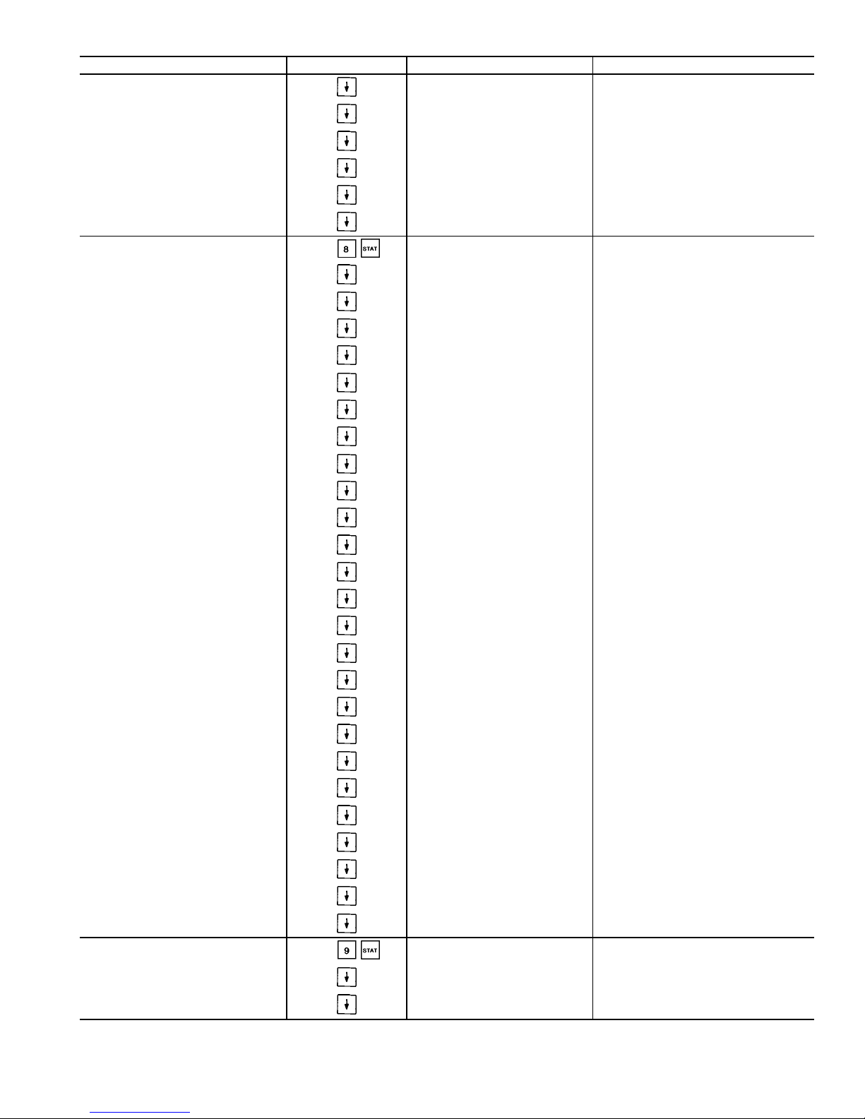
Table 10 — Status Function and Subfunction Directory (cont)
SUBFUNCTION KEYPAD ENTRY DISPLAY COMMENT
7 Unit Analog Parameters (cont)
TEMPERATURE RESET
4-20 mA Reset Signal
xx.x mA
Return Reset Signal
xx.x dF
External Reset Signal
xx.x dF
Outdoor Air Temp
xx.x dF
Calculated Reset
xx.x dF
8 Misc. Inputs/Outputs
MISC INPUTS/OUTPUTS
FAN_1
Off/On
FAN_2
Off/On
FAN_3
Off/On
FAN_4
Off/On
FAN_5
Off/On
FAN_6
Off/On
DEMAND LIMIT
4-20 mA Demand Signal
xx.x mA
Demand Switch 1
Off/On
Demand Switch 2
Off/On
CCN Loadshed Signal
Normal/Alarm
Max Allowable CAP
xxx.x%
PUMPS
Cooler Pump Relay
Off/On
Cooler Pump Flow Switch
Off/On
Condenser Pump Relay
Off/On
Condenser Pump Flow Switch
Off/On
MISCELLANEOUS
Ice Valve
Off/On
Ice Build Complete
Yes/No
Heat/Cool Switch
Heat/Cool
Dual Set point Switch
Off/On
Cooler Heater
Off/On
Options Temperature 1
xx.x dF
Not Used
Options Temperature 2
xx.x dF
Not Used
9 Operating Modes
MODES :MODE_TBL
mode name ON/OFF
Only active modes displayed
LOCAL OFF Scroll with down arrow key to display
CCN OFF
21

Table 10 — Status Function and Subfunction Directory (cont)
SUBFUNCTION KEYPAD ENTRY DISPLAY COMMENT
9 Operating Modes (cont)
CLOCK OFF
LOCAL ON
CCN ON
CLOCK ON
DUAL SP ACTIVE (1st SP)
DUAL SP ACTIVE (2nd SP)
TEMPERATURE RESET
ACTIVE
DEMAND LIMIT ACTIVE
LOAD LIMIT ACTIVE
LOW SOURCE TEMP PROTECT
RAMP LOADING ACTIVE
TIMED OVERRIDE ACTIVE
LOW COOLER SUCTION TEMP
WSM CONTROLLING
SLOW CHANGE OVERRIDE
OFF TO ON DELAYACTIVE
FSM CONTROLLING
2 CHILLR LEAD LAG ACTIVE
2 CHILLR LL COMM FAILURE
CIR A LOW DISCHG SUPERHT
CIR B LOW DISCHG SUPERHT
CIR A HIGH SDT
CIR B HIGH SDT
10 Capacity Control
CAPACITY CONTROL
Load/Unload Factor
xxx.x%
Control Point
xx.x dF
Leaving Water Temp
xx.x dF
MISC. INDICATORS
Liquid Lvl Sensor Cir. A
xx.x dF
Liquid Lvl Sensor Cir. B
xx.x dF
22
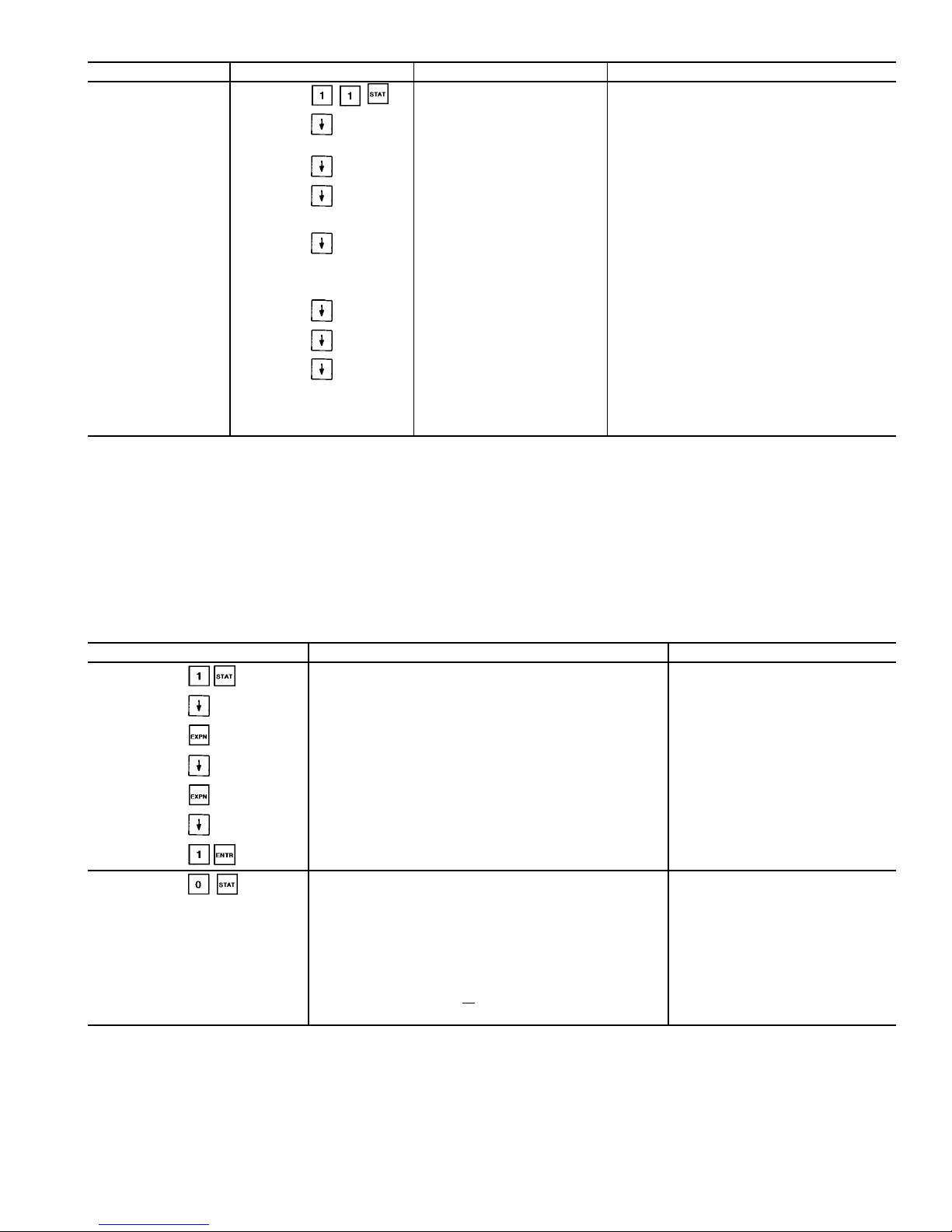
Table 10 — Status Function and Subfunction Directory (cont)
SUBFUNCTION KEYPAD ENTRY DISPLAY COMMENT
11 Dual Chiller
DUAL CHILLER
Unit Master / Slave
0/1/2
0 = Neither
1 = Slave
2 = Slave
Master / Slave Ctrl Active
Yes/No
Lead Chiller
1/2
1 = Master
2 = Slave
Slave Chiller State
0/1/3/5/6
0 = Chiller OFF
1 = Valid Run State in CCN Mode
3 = Chiller in Local Mode
5 = Shutdown on Alarm
6 = Communications Failure
Slave Chiller Total Cap
xxx.x%
Lead / Lag Changeover Yes if Lead / Lag Balance Enabled
Master / Slave Error
1/2/3/4/5/6
1 = Master / Slave Have Same Address
2 = Master / Slave Communication Failure
3 = Chiller in Local Mode
4 = Slave Shutdown on Alarm(s)
5 = Master Configured for Heating
6 = No Slave Configured
LEGEND
CCN — Carrier Comfort Network
CPM — Compressor Protection Module
dF — Degrees Fahrenheit
EXV — Electronic Expansion Valve
FSM — Flotronic™ System Manager
LL — Lead/Lag
SAT — Saturated
SDT — Saturated Discharge Temperature
SP — Set Point
WSM — Water System Manager
Table 11 — Reading and Clearing Alarms
KEYPAD ENTRY DISPLAY COMMENT
Alarm: 02
Reset Alarms: 1 <ENTER>
Comp A1 Fail - 1.70 Volt
Alarm : 15:12 04/15/96
Comp A1 Fail - 1.70 Volts Phase Reversal
Alarm : 15:12 04/15/96
Compressor A1 Low Oil Pr
Alarm : 10:34 04/15/96
Compressor A1 Low Oil Pressure
Alarm : 10:34 04/15/96
Alarm: 02
Reset Alarms: 1 <ENTER>
Press Reset
button first
Alarm: 00
Reset Alarms: 1 <ENTER>
Alarms reset
and cleared
Entering Fluid Temp
xx.x dF
Returns to rotating
default display
Leaving Fluid Temp
xx.x dF
Percent Total Capacity
xxx.x%
Total Number of Alarms
xx
MODES: MODE
TBL
List of All Current Modes
23

Table 12 — Operational and Mode Display Codes
CODE DESCRIPTION
LOCAL OFF Unit is off. LOCAL/OFF/REMOTE switch is
in OFF position or LOCAL/OFF/REMOTE
switch is in REMOTE position and remote
contacts are open.
CCN OFF Unit is off. LOCAL/OFF/REMOTE switch is
in LOCAL position and CCN control is
enabled (Stop state) or CCN is enabled
(Stop state) with LOR switch in REMOTE
position and remote contacts closed.
CLOCK OFF Unit is off due to internal clock schedule.
LOR switch is in LOCAL position.
LOCAL ON Unit is on. LOR switch is in LOCAL position
and CCN is disabled or LOR switch is in
REMOTE position with contacts closed and
CCN is disabled.
CCN ON Unit is on due to CCN command. LOR
switch is in LOCAL position and CCN is
enabled (Run state) or LOR switch is in
REMOTE position with contacts closed and
CCN is enabled (Run state)
CLOCK ON Unit is on due to internal clock schedule or
occupied override function. LOR switch is
in LOCAL position.
DUAL SP ACTIVE
(1st SP)
Dual set point is in effect. In this mode, unit
continues to run in an occupied condition,
and leaving fluid set point is automatically
controlled to the CSP1 set point in the SET
POINT function.
DUAL SP ACTIVE
(2nd SP)
Dual set point is in effect. In this mode, unit
continues to run in unoccupied condition,
but leaving fluid set point is automatically
increased to a higher level (CSP2 set point
is in SET POINT function).
TEMPERATURE
RESET ACTIVE
Temperature reset is in effect. In this mode,
unit is using temperature reset to adjust
leaving fluid set point upward, and unit is
currently controlling to the modified set
point. The set point can be modified based
on return fluid, outdoor-air temperature,
space temperature, or 4 to 20 mA signal.*
DEMAND LIMIT
ACTIVE
Demand limit is in effect. This indicates that
capacity of unit is being limited by demand
limit control option. Because of this
limitation, the unit may not be able to
produce the desired leaving fluid
temperature. Demand limit can be controlled
by a switch or 4 to 20 mA signal.*
FSM
CONTROLLING
Flotronic™ System Manager (FSM) is
controlling the chiller.
RAMP LOADING
ACTIVE
Ramp load (pulldown) limiting is in effect.
In this mode, the rate at which leaving fluid
temperature is dropped is limited to a
predetermined value to prevent compressor
overloading. See CRAMP set point in the
SET function in (page 25). The pulldown limit
can be modified, if desired, to any rate from
0.2° F to 2° F (0.1° to 1° C)/minute.
TIMED OVERRIDE
ACTIVE
Timed override is in effect. This isa1to
4 hour temporary override of the programmed schedule, forcing unit to occupied
mode. Override can be implemented with
unit under LOCAL/REMOTE or CCN control.
Override expires after each use.
WSM
CONTROLLING
Water System Manager is controlling the
chiller.
SLOW CHANGE
OVERRIDE
Slow change override is in effect. The
leaving fluid temperature is close to and
moving towards the control point.
CODE DESCRIPTION
OFF TO ON
DELAY ACTIVE
Chiller is being held off by Minutes Off Time
found by keying . Also, normal
operation of the chiller includes a minimum
1.5 minute delay after a capacity stage
change has been made. This delay is
adjustable from 1.5 to 6 minutes.
LOAD LIMIT
ACTIVE
This function determines the maximum
allowable capacity that can be running and
is accomplished through the Flotronic
System Manager. The unit may not be able
to produce the desired leaving fluid
temperature.
2 CHILLR LEAD
LAG ACTIVE
Future Use.
2 CHILLR LL
COMM FAILURE
Future Use.
CIRCUIT A LOW
DISCHARGE
SUPERHT
If the circuit discharge superheat is less
than 15° F (8.3° C), the capacity control
routine will not add any stages (to either
circuit).
If the compressor has been running for at
least 3 minutes, the EXV will not be
opened any further. If the circuit
discharge superheat is less than 10° F
(5.6° C) and falling, the circuit EXV will
be closed 50 steps every 10 seconds.
If the discharge superheat is less than
5° F (2.8° C) and falling, a circuit loader
will be deenergized every 30 seconds.
The final stage will not be unloaded
unless an alarm condition is present.
CIRCUIT B LOW
DISCHARGE
SUPERHT
See description for Circuit A above.
CIRCUIT A
HIGH SCT
If the circuit is running and the Saturated
Condensing Temperature (SCT) is greater
than the Maximum Condensing
Temperature Set point (MCT_SP) minus
12° F (6.7° C), the control will not add
any stages.
If the SCT is greater than the MCT_SP
plus 5° F (2.8° C), the circuit will be
unloaded and shut down if necessary. If
the SCT is greater than the MCT_SP plus
2° F (1.1° C) for one minute, a loader will
be deenergized.
If the SCT is greater than the MCT_SP
minus 4° F (2.2° C), the control will
compare the maximum operating
pressure set point (MOP_SP) with the
modified MOP_SP (MOP_CTRL).
If the MOP_CTRL is greater than the
MOP_SP, the mode will be cleared.
Otherwise the control will display the
high SCT override mode. The capacity
control routine will not add any stages. If
the circuit is at its lowest capacity, this
mode will be ignored.
CIRCUIT B
HIGH SCT
See description for Circuit A above.
LEGEND
CCN — Carrier Comfort Network
CSP — Cooling Set Point
CRAMP — Cooling Ramp Loading
EXV — Electronic Expansion Valve
LOR — Local/Off/Remote
SP — Set Point
WSM — Water System Manager
*Afield-supplied500Ohm
1
⁄2W resistor must be installed across the
input terminals when usinga4to20mAsignal.
Table 13 — Reading Current Operating Modes
KEYPAD ENTRY DISPLAY
MODES :MODE_TBL
CCN ON
DEMAND LIMIT
ACTIVE
24

TEST FUNCTION — The test function operates the diagnostic program. To initiate the test function, the LOCAL/
OFF/REMOTE switch must be in the OFF position.
To reach a particular test, press its subfunction number
followed by the key then scroll to the desired test by
pressing the down arrow key. Refer to Table 14 for a com-
plete description of the test function.
To start a test of discrete outputs, press . To end
the test, simply press the key or press . Pressing
the key after a test has started advances the system to
the next test, whether the current test is operating or has timed
out. Circuit A discrete outputs can be tested in and
include loaders, minimum load valve, oil heater (if equipped),
motor cooling solenoids, oil pump, and oil solenoids. Similarly, Circuit B discrete outputs can be tested in
.Additionaldiscrete outputs, including condenser fans,
cooler heater, water pumps, and remote alarms can be tested
in .
Press to access Valves and Motormastert device
analog outputs. Scroll down to display Circuit A EXV Valve
with a target percent of 0%. Press to step the EXV
to 25%. Pressing three additional times will move
the EXV to 50%, 75%, and 100%. The EXV may be closed
in 25% steps by pressing for each desired step. Wait
30 seconds between each step when opening and closing for
the valve to stop moving. Pressing the down arrow will display Circuit B EXV Valve and it is tested in the same manner as Circuit A. Also available for test are Circuit A water
valve (if equipped) and the Circuit A and B Fan speed %
(direct control Motormaster device) outputs for 30GX chillers. These are tested in the same manner as the EXV valves.
Note that condenser fan motors are NOT started during fan
speed quick tests. Measure 4 to 20 mA dc output using meter
in series with violet wire to controller. See page 72 of Field
Wiring section.
While the unit is in test, you can leave the test function
and access another display or function by pressing the appropriate keys. However,a component that is operating when
another function is accessed remains operating. You must
re-enter the test function and press to shut down the
component. Components with a timed operating limit time
out normally even if another function is accessed.
Since the Test function checks only certain outputs, it is
a good practice to also check all inputs and outputs accessible through the status function. These can be located by
pressing through . If keypad is not used for
10 minutes, the unit automatically leaves the test function
and resumes the normal rotating display. See Table 15.
HISTORY FUNCTION — Pressing displays total
machine operating hours. Scroll down to display machine
run time and starts, and total run time and starts for each
compressor. Refer to Table 16 for a complete description of
the function. When the PSIO-1 module is replaced or downloaded with Version 4.0 or later software, the number of starts
and run hours may be changed one time. Record the current
values from the PSIO before removing the module or downloading new software. The number of starts and hours may
be changed by entering the desired value at the HSIO and
pressing the key.
Pressing displays the last 10 alarms along with a
description and time and date of occurrence of each alarm.
SET POINT FUNCTION — Set points are entered through
the keypad. Set points can be changed within the upper and
lower limits, which are fixed. The ranges are listed below.
Refer to Table 17 for a complete description of the function.
Cooling Set Point 1,2
Water:
Medium
Temperature Brine:
Low
Temperature Brine:
38 to 70 F
(3.3 to 21.1 C)
14 to 70 F
(−10 to 21.1 C)
−13 to 70 F
(−25 to 21.1 C)
Reset Set Points
Maximum
Reset Range:
−30 to 30 F
(−17 to 17 C)
External Temperature
Reset:
−40 to 240 F
(−40 to 118 C)
Chiller Fluid D:
0° to 15 F
(0° to 8 C)
External Signal Reset: 4 to 20 mA (2-10 vdc with
500 Ohm resistor)
Demand Limit Set Points
Switch Input: Step1—0to100% Capacity Reduction
Step2—0to100% Capacity Reduction
External Signal: Maximum Demand Limit 4 to 20 mA
(2-10 vdc with 500 Ohm resistor)
Minimum Demand Limit 4 to 20 mA
(2-10 vdc with 500 Ohm resistor)
Loadshed Demand Delta: 0 to 60%
Maximum Loadshed Time: 0 to 120 min.
Head Pressure Set Points
Air cooled chillers (30GX): 80 to 135 F (26.7 to 57.2 C)
Water cooled chillers (30HX): 80 to 128 F (26.7 to 53.3 C)
Set Point Table — The unit operating set points can be found
under . Use the down arrow key to scroll through
the set points. The first set point is Cool Set Point 1. This is
the occupied chilled fluid set point. Scroll down to Cool Set
Point 2 and then to the Cooling Ramp load multiplier which
is configurable from 0.2 to 2.0° F/min. (0.11 to 1.1° C/min.).
This value is the maximum rate at which the leaving fluid
temperature is allowed to drop without adding a stage. Cooling Set Point 2 is used in conjunction with the dual set point
switch function. This is used as the low temperature set point
for ice duty or as the unoccupied set point. Press the down
arrow key to display the Circuit A and B head pressure set
points. The remaining set points in this subfunction include
demand limit, LCW (leaving chilled water) delta alarm limit,
minutes off time, and motor temperature set point.
Display Units — Press to display the units of measure being used. Type 0 is for English and type 1 is for
Metric.
Address — For CCN configurations, press and
scroll down to display the address and bus number of the
chiller.
Time — Press and scroll down to read and change
the unit day of week, time, day of month, month of year and
year of century. See the examples in Table 17 for making
changes to these values.
CCN Enable/Disable — Press to disable the CCN
control of the chiller. This function will override CCN con-
trol commands. The CCN Enable value under must
be ON to activate this function. With CCN Enable set to ON
and Disable CCN Control set to ‘‘0,’’ the chiller will function normally under CCN control. With Disable CCN Control set to ‘‘1,’’ the chiller will operate in a local mode under
its own control.
Reading and Changing Set Points — Table 18 shows how
to read and change the chilled fluid set point. Other set points
can be changed by following the same procedure. Refer to
Table 17 for the sequence of display of set points in each
subfunction.
25

Table 14 —Test Function and Subfunction Directory
SUBFUNCTION KEYPAD ENTRY DISPLAY COMMENT
1 Circuit A Discrete Output
Circuit A Discrete Output
Loader A1
Relay is OFF
Loader A1
Relay is ON
Loader A2 Similarly, use to test remaining outputs. Press the
down arrow key or to turn an output off.
Minimum Load Valve A
Circuit A Oil Heater
A1 Mtr. Cooling Solenoid
A2 Mtr. Cooling Solenoid
Circuit A Oil Pump
Oil Solenoid A1
Oil Solenoid A2
NOTE: Output will display Relay is ABSENT when
not configured
2 Circuit B Discrete Outputs
Circuit B Discrete Outputs
Loader B1
Relay is OFF
Loader B1
Relay is ON
Loader B2 Similarly, use to test remaining outputs. Press the
down arrow key or to turn the output off.
Minimum Load Valve B
Circuit B Oil Heater
B1 Mtr. Cooling Solenoid
B2 Mtr. Cooling Solenoid
Circuit B Oil Pump
Oil Solenoid B1
Oil Solenoid B2
NOTE: Output will display Relay is ABSENT when
not configured
3 Unit Discrete Output
Unit Discrete Output
Fan 1
Relay is OFF
Fan 1
Relay is ON
Fan 2 Similarly use to test remaining outputs. Press the
down arrow key or to turn output off.
Fan 3
Fan 4
Fan 5 Energizes Circuit A fans for 30HXA units.
Fan 6 Energizes Circuit B fans for 30HXA units.
Cooler Pump
Condenser Pump
Cooler Heater
Alarm
Remote Alarm 1 Currently not supported.
26

Table 14 —Test Function and Subfunction Directory (cont)
SUBFUNCTION KEYPAD ENTRY DISPLAY COMMENT
3 Unit Discrete Output (cont)
Remote Alarm 2 Currently not supported.
Remote Alarm 3 Currently not supported.
Remote Alarm 4 Currently not supported.
Remote Alarm 5 Currently not supported.
Remote Alarm 6 Currently not supported.
Remote Alarm 7 Currently not supported.
Remote Alarm 8 Currently not supported.
Remote Alarm 9 Currently not supported.
Remote Alarm 10 Currently not supported.
Remote Alarm 11 Currently not supported.
Remote Alarm 12 Currently not supported.
Remote Alarm 13 Currently not supported.
Remote Alarm 14 Currently not supported.
Remote Alarm 15 Currently not supported.
Remote Alarm 16 Currently not supported.
4 Valves and Motormaster
Valves and Motor Master
Circuit A EXV Valve
Target Percent = 0%
Circuit A EXV Valve
Target Percent = 25%
Step in 25% increments.
Circuit A EXV Valve
Target Percent = 50%
Wait 30 seconds between each step for valve to stop moving.
Circuit A EXV Valve
Target Percent = 75%
Valve may be closed in 25% increments by keying in .
Wait 30 seconds between each step for valve to stop moving.
Circuit A EXV Valve
Target Percent = 100%
Circuit B EXV Valve
Target Percent = 0%
Test same method as for Circuit A
Circuit A Water Valve
Target Percent = 0%
Test same method as for EXV valves
Circuit A% Fan Speed Test same method as for EXV valves
Circuit B% Fan Speed Test same method as for EXV valves
LEGEND
EXV — Electronic Expansion Valve
Table 15 — Using Test Function
KEYPAD ENTRY DISPLAY RESPONSE COMMENTS
Circuit A Discrete Output
Loader A1
Relay is OFF
Appears on screen momentarily, then will switch to Loader A1.
Loader A1
Relay is ON
Compressor Loader A1 solenoid energized
Loader A1
Relay is OFF
Compressor Loader A1 solenoid deenergized
Valves and Motor Master
Circuit A EXV Valve
Target Percent = 0%
Circuit A EXV Valve
Target Percent = 25%
Continue pressing to step to 50%, 75%, and 100%.
Circuit A EXV Valve
Target Percent = 0
Continue pressing to step closed.
LEGEND
EXV — Electronic Expansion Valve
27

Table 16 — History Function and Subfunction Directory
SUBFUNCTION KEYPAD ENTRY DISPLAY COMMENT
1 Operating Hours
Machine Operating Hours
xxx.x hours
Number of hours unit has at least
1 compressor running
Number of unit starts from
zero capacity
These values may be changed once, when new software is downloaded or when the PSIO-1 module is replaced (Version 4.0 and later).
Machine Starts
xxx
Circuit A
Operating Hours
xxx.x hours
Compressor A1 Hours
xxx.x hours
Compressor A2 Hours
xxx.x hours
Starts
Compressor A1 Starts
xxx
Compressor A2 Starts
xxx
Circuit B
Operating Hours
xxx.x hours
Compressor B1 Hours
xxx.x hours
Compressor B2 Hours
xxx.x hours
Starts
Compressor B1 Starts
xxx
Compressor B2 Starts
xxx
2 Alarm History
Previous Alarm 1 - description
Alarm description, time/day
of occurrence
Lists 10 most recent alarms. Use key when necessary
Previous Alarm 2 - description
Alarm description, time/day
of occurrence
Previous Alarm 3 - description
Alarm description, time/day
of occurrence
Previous Alarm 4 - description
Alarm description, time/day
of occurrence
Previous Alarm 5 - description
Alarm description, time/day
of occurrence
Previous Alarm 6 - description
Alarm description, time/day
of occurrence
Previous Alarm 7 - description
Alarm description, time/day
of occurrence
Previous Alarm 8 - description
Alarm description, time/day
of occurrence
Previous Alarm 9 - description
Alarm description, time/day
of occurrence
Previous Alarm 10- description
Alarm description, time/day
of occurrence
28

Table 17 — Set Point Function and Subfunction Directory
SUBFUNCTION KEYPAD ENTRY DISPLAY COMMENT
1 Set Point Table
COOLING
Cool Setpoint 1
xx.x dF
Default: 44.0
Cool Setpoint 2
xx.x dF
Default: 44.0
Cooling Ramp Loading
xx.x dF
Default: 0.5
HEATING NOT SUPPORTED
Heat Setpoint 1
xx.x dF
NOT SUPPORTED
Default: 98.0
Heat Setpoint 2
xx.x dF
NOT SUPPORTED
Default: 98.0
Heating Ramp Loading
xx.x dF
NOT SUPPORTED
Default: 0.5
HEAD PRESSURE
Head Pressure Setpoint A
xxx.x dF
Default: 113.0 (GX)
100.0 (HXA) 85.0 (HXC)
Head Pressure Setpoint B
xxx.x dF
Default: 113.0 (GX)
100.0 (HXA) 85.0 (HXC)
DEMAND LIMIT
Demand Switch 1 Setpoint
xxx.x%
Default: 80.0%
Demand Switch 2 Setpoint
xxx.x%
Default: 50.0%
LCW Delta Alarm Limit
xxx.x dF
Default: 50.0 dF
Minutes Off Time
xxx min
Default: 0 min
Motor Temp Set Point
xxx.x dF
Default: 200.0 dF
2 Units
US IMPERIAL/METRIC
0
0 = English (Default)
1 = Metric
3 Address
TARGETADDRESS
x
Default: 1
TARGET BUS NUMBER
x
Default: 0
4 Time
Day of Week
Monday
Mon=1, Tues=2, etc.
Day of Week
Wednsday
Day of week set
TIME (HOUR:MIN)
00:00
Enter military format
TIME (HOUR:MIN)
10:30
Time of day set
DAY OF MONTH
xx
DAY OF MONTH
20
Day of month set
MONTH OF YEAR
xx
MONTH OF YEAR
05
Month of year set
YEAR OF CENTURY
xx
YEAR OF CENTURY
96
Year of century set
5 CCN Disable
Disable CCN Control
x
0=no, 1=yes
Default: 0
LEGEND
CCN — Carrier Comfort Network
LCW — Leaving Chilled Water
NOTE: If metric option is selected under , temperatures are expressed
in degrees Celsius and pressures are expressed in kPa.
29

Table 18 — Reading and Changing
Chilled Fluid Set Point
KEYPAD ENTRY DISPLAY RESPONSE COMMENTS
COOLING Change set point from
default to 48 F.
Cool Set point 1
44.0 F default
Cool Set point 1
48.0 F
Set point change
complete
SERVICE FUNCTION — This function allows the technician to view and input configuration data. Factory configuration data, field configuration data, and service configuration data may be viewed or entered through the keypad and
display module. See Table 19 for a complete listing of configurable items. Whenever a processor module is replaced in
the field, the complete list of configuration codes should be
checked for correct settings. The current software version
can be displayed. See Table 20.
Scroll down in this function to display configuration information including number of compressors, tonnage, and
compressor must-trip amps.
Password Protection of HSIO Configurable Service Points
— To modify configurations and values and to use the manual
control subfunction, the password must be entered before the
first change can be made. The default password is set to
. See Table 21 for an example of how to
enter the password to change the Lead/Lag configuration.
Options Configuration Tables 1 and 2 — These subfunc-
tions can be accessed by pressing or and scrolling down to display the configuration options. See Table 19
for a complete list of these options.
Temperature Reset, Demand Limit and Head Pressure PID
Configurations —Press andscrolldowntoview the
configuration information. See Table 19 for a complete list.
Factory Configuration Codes — Pressing allows
entry into the factory and service configuration codes
subfunction. Under this subfunction, there are 5 configuration codes that are downloaded at the factory. Each code is
made up of 8 digits. If the processor module is replaced in
the field, these 5 configuration codes should be checked using the keypad and HSIO display module. See Table 22 for
a descriptionofthefactory configuration codes (codes 1 through
3) and service configuration codes (codes 4 and 5).
The factory and service configuration codes are found by
pressing . These are preset from the factory.They can
be verified by following the description in Table 22. These
codes MUST be checked and corrected in the field if the
PSIO-1 module is replaced.
NOTE: The LOCAL/OFF/REMOTE switch must be in the
OFF position to change configuration codes.
A label is applied to a control box panel with a list of
factory and service codes for particular units. Table23shows
how to configure a new PSIO-1 module for use in a 30HXC106---501CA water cooled chiller.
Transducer Calibration — Press and scroll down to
view the transducer calibration information. See Table 19
for a complete list, and the Pressure Transducers section on
page 59 for a description of this subfunction.
Manual Control Mode — This control allows the user to
have full control over the compressors, loaders, and the minimum load valve (if installed) of the machine. Normal safeties such as high pressure, oil level and pressure, and CPM
related alarms are NOT bypassed in this control mode. The
capacity control function and overrides ARE bypassed when
using the manual control mode. To enter this mode, switch
the LOR switch to OFF. Press at the HSIO. The display will read Manual Control Enable - Disable. Press
and switch the LOR switch to Local. The display will change
to Manual Control Enable - Enable. The Disable and Enable
will appear on the second line of the display. See Table 19
for a complete list of this function.
Scroll down and press to start the desired com-
pressor.The control will start the compressor if the pre-lube
cycle is passed, just as in normal operation. Press to
add loaders as desired and press to turn off loaders
and compressors. The Minimum Load Valve can be energized using the same procedure.
Dual Chiller Configuration — Press to enter the Dual
Chiller control configuration. This method of control is for
a stand-alone Master/Slave combination of chillers and will
NOT work with the Flotronic™ System Manager (FSM).
The Minus One Pass Cooler option is required for this
configuration.
The chillers should be piped for series flow through the
coolers. The Master chiller must be downstream from the
Slave chiller leaving water.BoththeMasterand Slave chiller
must be connected to the same CCN Level II communications bus with different addresses. To enable the dual chiller
configuration the CCN Enable function must be set
to Enable for each chiller, otherwise each chiller will oper-
ate independently. This value can be activated through the
HSIO or through a CCN device. Both chillers should be con-
figured for Close Control and require flow switches
to be installed. For cooler pump control, wire both Master
and Slave chiller outputs to the cooler pump starter.All system inputs (temperature reset, demand limit, dual set point,
etc.) should be connected to the Master chiller. If Lead/Lag
Balance is disabled, the Master chiller will always be the
lead chiller. If Lead/Lag Balance is enabled, the control will
alternate between the Master and Slave chillers to keep their
respective run hours balanced within the value configured
for Lead/Lag Balance Delta. The desired leaving fluid set
point for the Duplex chiller must be configured in
the Master chiller. CCN Control of the chillers can be dis-
abled locally through the HSIO by entering and enabling the Disable CCN Control value. This value must be
disabled before the chiller will return to Duplex control.
30
 Loading...