


30RY
Table of contents
 Loading...
AQUASNAP
30RA/RH “B”
30RY/RYH “B”
PRO-DIALOG Control
Operation and maintenance instructions

TABLE OF CONTENTS
1 - SAFETY CONSIDERATIONS..................................................................................................................................................4
1.1 - General .................................................................................................................................................................................4
1.2 - Avoid electrocution ..............................................................................................................................................................4
2 - GENERAL DESCRIPTION ......................................................................................................................................................4
2.1 - General .................................................................................................................................................................................4
2.2 - Abbreviations used ...............................................................................................................................................................4
3 - HARDWARE DESCRIPTION..................................................................................................................................................5
3.1 - General .................................................................................................................................................................................5
3.2 - Electrical supply to boards ...................................................................................................................................................5
3.3 - Light emitting diodes on boards...........................................................................................................................................5
3.4 - The sensors ...........................................................................................................................................................................5
3.5 - The output controls...............................................................................................................................................................5
3.6 - Connections at the user's terminal block ..............................................................................................................................6
3.6.1 - General description ......................................................................................................................................................6
3.6.2 - Volt-free contact on/off/cooling/heating without multiplexing ..................................................................................8
3.6.3 - Volt-free contact on/off/cooling/heating with multiplexing........................................................................................8
3.6.4 - Demand limit or setpoint volt-free contact for single-circuit units .............................................................................8
3.6.5 - Demand limit volt-free contact for dual-circuit units ..................................................................................................8
3.6.6 - Water setpoint selection volt-free contact with multiplexing for dual-circuit units....................................................8
4 - SETTING UP PRO-DIALOG CONTROL ..............................................................................................................................9
4.1 - Local interface general features............................................................................................................................................9
4.2 - Unit start/stop control .........................................................................................................................................................10
4.2.1 - Description................................................................................................................................................................. 10
4.2.2 - Stopping the unit in local mode .................................................................................................................................10
4.2.3 - Starting unit and selecting an operating type............................................................................................................. 10
4.3 - Menus .................................................................................................................................................................................11
4.3.1 - Selecting a menu ........................................................................................................................................................11
4.3.2 - Selecting a menu item................................................................................................................................................ 11
4.3.3 - Modifying the value of a parameter/access to a sub-menu........................................................................................11
4.3.4 - Expand display...........................................................................................................................................................12
4.3.5 - Description of the Information menu.........................................................................................................................15
4.3.6 - Description of the Temperatures menu......................................................................................................................17
4.3.7 - Description of the Pressures menu.............................................................................................................................17
4.3.8 - Description of the Setpoints menu............................................................................................................................. 17
4.3.9 - Description of the Inputs menu..................................................................................................................................18
4.3.10 - Description of the Outputs/Tests menu ...................................................................................................................19
4.3.11 - Description of the configuration menu ....................................................................................................................22
4.3.12 - Description of the Alarms menu ..............................................................................................................................28
4.3.13 - Description of the Alarms History menu .................................................................................................................28
4.3.14 - Runtime menu description .......................................................................................................................................28
2

5 - PRO-DIALOG CONTROL OPERATION ............................................................................................................................29
5.1 - Start/stop control ................................................................................................................................................................29
5.2 - Heating/cooling operation ..................................................................................................................................................30
5.2.1 - General.......................................................................................................................................................................30
5.2.2 - Heating/cooling selection ..........................................................................................................................................30
5.3 - Evaporator water pump control ..........................................................................................................................................31
5.4 - Control interlock contact ....................................................................................................................................................31
5.5 - Evaporator heater control ................................................................................................................................................... 31
5.6 - Control point.......................................................................................................................................................................31
5.6.1 - Active setpoint ...........................................................................................................................................................31
5.6.2 - Reset...........................................................................................................................................................................33
5.7 - Demand limit ......................................................................................................................................................................33
5.8 - Night mode .........................................................................................................................................................................33
5.9 - Capacity control..................................................................................................................................................................33
5.10 - Head pressure control .......................................................................................................................................................33
5.11 - Defrost function................................................................................................................................................................34
5.12 - Additional electric heater stage control ............................................................................................................................34
5.13 - Control of a boiler ............................................................................................................................................................34
5.14 - Master/slave assembly...................................................................................................................................................... 34
5.15 - Controlling Pro-Dialog units with a System Manager .....................................................................................................34
6 - DIAGNOSTICS - TROUBLESHOOTING ............................................................................................................................35
6.1 - General ...............................................................................................................................................................................35
6.2 - Displaying alarms...............................................................................................................................................................35
6.3 - Resetting alarms .................................................................................................................................................................35
6.4 - Alarm codes........................................................................................................................................................................35
Each of the following drawings is replaced in the whole document by the corresponding explanation:
GENERAL LEGEND
Start/stop button
Return key
Down arrow
Up arrow
DELTA T. Example: temperature difference between entering and leaving heat exchanger temperatures
means character is flashing
The cover graphics are solely for illustration and forms no part of any offer for sale or any sale contract. The manufacturer
reserves the right to change the design at any time without notice.
3

1 - SAFETY CONSIDERATIONS
2 - GENERAL DESCRIPTION
1.1 - General
Installation, start-up and servicing of equipment can be
hazardous if certain factors particular to the installation are not
considered: operating pressures, presence of electrical
components and voltages and the installation site (elevated
plinths and built-up up structures). Only properly qualified
installation engineers and highly qualified installers and
technicians, fully trained for the product, are authorised to
install and start-up the equipment safely. During all ser vicing
operations all instructions and recommendations which appear
in the installation and service instructions for the product, as
well as on tags and labels fixed to the equipment and
components and accompanying parts supplied separately, must
be read, understood and followed.
• Apply all standard safety codes and practices.
• Wear safety glasses and gloves.
• Use the proper tools to move heavy objects. Move units
carefully and set them down gently.
1.2 - Avoid electrocution
Only personnel qualified in accordance with IEC (International
Electrotechnical Commission) recommendations may be
permitted access to electrical components. It is particularly
recommended that all sources of electricity to the unit be shut
off before any work is begun. Shut off the main power supply
at the main circuit breaker or isolator.
IMPORTANT: This equipment uses and emits
electromagnetic signals. Tests have shown that the equipment
conforms to all applicable codes with respect to
electromagnetic compatibility.
RISK OF ELECTROCUTION: Even when the main circuit
breaker or isolator is switched off, certain circuits may still
be energised, since they may be connected to a separate power
source.
RISK OF BURNS: Electrical currents cause components to
get hot either temporarily or permanently. Handle power
cable, electrical cables and conduits, terminal box covers and
motor frames with great care.
Fan start-up:
ATTENTION: In accordance with the operating conditions
the fans can be cleaned periodically. A fan can start at any
time, even if the unit has been shut down.
2.1 - General
Pro-Dialog is a system for controlling single or dual-circuit
30RA/RY air-cooled liquid chillers or air-to-water 30RH/RYH
heat pumps. Pro-Dialog controls compressor start-up needed to
maintain the desired heat exchanger entering or leaving water
temperature. In cooling mode it controls the operation of the fans
to maintain the correct condensing pressure in each circuit. For
heat pump units it controls and optimises the defrost cycles of
each circuit in order to minimize the heating capacity
reduction. Safety devices are constantly monitored by ProDialog to ensure their safe operation. Pro-Dialog also gives
access to a Quick Test program covering all inputs and outputs.
All PRO-DIALOG controls can work in accordance with three
independent modes:
• Local mode: the machine is controlled by commands from
the user interface.
• Remote mode: the machine is controlled by remote
contacts (volt-free contacts).
• CCN mode: the machine is controlled by commands from
the Carrier Comfort Network (CCN). In this case, a data
communication cable is used to connect the unit to the
CCN communication bus.
The operating mode must be chosen with the Start/Stop button
described in section 4.2.1. When the PRO-DIALOG system
operates autonomously (Local or Remote mode) it retains all of
its own control capabilities but does not offer any of the
features of the CCN network.
2.2 - Abbreviations used
In this manual, the refrigeration circuits are called circuit A and
circuit B. The compressors in circuit A are labelled A1, A2 and
A3. Those in circuit B are B1, B2 and B3.
The following abbreviations are used fr equently:
CCN : Carrier Comfort Network
CCn : Operating type: CCN
LED : Light Emitting Diode
LOFF : Operating type: Local Off
L-On : Operating type: Local On mode
L-Sc : Operating type: Local On following a time schedule
MASt : Operating type: master unit (master/slave assembly)
rEM : Operating type: by remote contacts
SCT : Saturated Condensing Temperature
SIO : Sensor Bus (internal communication bus linking the
basic board to the slave boards)
SST : Saturated Suction Temperature
TXV : Thermal Expansion Valve
4
3 - HARDWARE DESCRIPTION
5
6
8
3.2 - Electrical supply to boards
3.1 - General
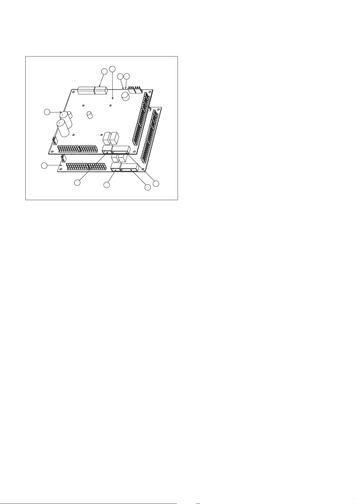
Figure 1
4
1
9
3
10
Legend
1 CCN connector
2 Red LED, status of the board
3 Green LED, communication bus SIO
4 Orange LED, communication bus CCN
5 Remote master board customer control connection contacts
6 Remote slave board customer control connection contacts
7 Master board customer connection relay outputs
8 Slave board customer connection relay outputs
9 Master NRCP basic board
10 Slave NRCP basic board
3
2
The control system consists of an NRCP-BASE board for
single-circuit units and two NRCP-BASE boards (a master and
a slave board) for dual-circuit units. Heat pump units equipped
with optional additional heater stages use an additional board,
type PD-AUX. All boards communicate via an internal SIO bus.
The NRCP-BASE boards continuously manage the information
received from the various pressure and temperature probes. The
NRCP-BASE master board incorporates the program that
controls the unit.
The user interface consists of two display blocks with up to 26
LEDs and 16 buttons (according to unit type). It is connected
to the main basic board and gives access to a full array of
control parameters.
All boards, except the PD-RCPM board, are supplied from a
common 24 V a.c. supply referred to earth.
CAUTION: Maintain the correct polarity when connecting
the power supply to the boards, otherwise the boards may be
damaged.
In the event of a power supply interrupt, the unit restarts
automatically without the need for an external command.
However, any faults active when the supply is interrupted are
saved and may in certain cases prevent a circuit or unit from
restarting.
3.3 - Light emitting diodes on boards
All boards continuously check and indicate the proper
operation of their electronic circuits. A light emitting diode
(LED) lights on each board when it is operating properly.
• The red LED flashing for a 2 second period on the NRCPBASE board indicates correct operation. A different rate
indicates a board or a software failure.
• On dual-circuit units or units equipped with optional
board, the green LED flashes continuously on all boards
to show that the board is communicating correctly over its
internal bus. If the LED is not flashing, this indicates a
SIO bus wiring problem.
• The orange LED of the master board flashes during any
communication via the CCN bus.
3.4 - The sensors
Pressure sensors
Two types of electronic sensors are used to measure the suction
and discharge pressure in each circuit.
Thermistors
The evaporator water sensors are installed in the entering and
leaving side. The outdoor temperature sensor is mounted below
the control box. An optional water system temperature sensor
can be used for master/slave assembly control (in the case of
leaving water control).
In heat pump units a sensor placed on an air heat exchanger
pipe ensures defrost operation.
5

3.5 - The controls
3.6 - Connections at the user's terminal block
Evaporator pumps
The controller can regulate one or two evaporator pumps and
takes care of automatic change-over between pumps.
Evaporator heater
It protects the evaporator (and the pipe heater for units without
pump) against freezing if the unit is off.
Boiler
This relay output authorises start/stop of a boiler.
Condensate defrost heater
This heater is used for heat pump units and is located at the
bottom of the air heat exchanger of each circuit. It prevents ice
build-up, if defrost cycles are initiated at low outdoor
temperatures.
SINGLE-CIRCUIT UNITS
Description
Alarm relay output
Boiler relay output
Connector/channel
J3 / CH24
J3 / CH25
Terminal
30 - 31
37 - 38
Board
NRCP-BASE
NRCP-BASE
3.6.1 - General description
The contacts below are available at the user's terminal block on
the NRCP-BASE board (see figure 1). Some of them can only
be used if the unit operates in remote operating type (rEM).
The following table summarises the connections at the user’s
terminal block.
Remarks
Indicates alarms
Boiler start/stop control output.
See section 5.13.
Remarks
Volt-free contact 24 V a.c.
48 V d.c. max, 20 V a.c. or
V d.c., 3 A max, 80 mA min,
external power supply .
Contact 1:
start/stop/heat/cool
Contact 2:
start/stop/heat/cool
Contact 3:
demand limit selection or
setpoint selection
User safety loop input
Connection to CCN
J4 / CH8
J4 / CH9
J4 / CH10
J4 / CH11a
J12
32 - 33
63 - 64
73 - 74
34 - 35
1 - 2 - 3
NRCP-BASE
NRCP-BASE
NRCP-BASE
NRCP-BASE
NRCP-BASE
The contacts are used for unit start/stop and
heat/cool control. The y are only taken into
account if the unit is under remote operation
control (rEM).
See the description of these contacts in
sections 3.6.2 and 3.6.3.
Depending on the configuration, this dry
contact can be used for remote setpoint
selection or demand limit selection (see
sections 4.3.11.3 and 3.6.4).
- The remote setpoint selection contact is
only taken into account if the unit is in
remote control operating type.
- The remote demand limit selection contact
is active whatever the operating type of the
unit.
This contact is mounted in series with the
water flow control contact. It can be used for
any customer safety loop that requires that
the unit is stopped, if it is open.
If it is unused this contact must be bridged.
An RS-485 bus is used for connection to the
CCN.
- Pin 1: signal +
- Pin 2: ground
- Pin 3: signal -
Connector: 4 pin
WAGO 734-104 pitch 3.5.
One per board needed.
24 V a.c., 20 mA
Connector: 8 pin WAGO
734-168, pitch 3.5
Connector: 3 pin WAGO
231-303, pitch 5.08
6

DUAL-CIRCUIT UNITS
Description
Alarm relay output
circuit A
Alarm relay output
circuit B
Boiler relay output
Contact 1:
start/stop/heat/cool
Contact 2:
start/stop/heat/cool
Contact 3:
demand limit selection
Contact 4:
demand limit selection
Contact 5:
setpoint selection
Control contact 6:
setpoint selection
User safety loop input
Connection to CCN
Connector/channel
J3 / CH24
J3 / CH24
J3 / CH25
J4 / CH8
J4 / CH9
J4 / CH10
J4 / CH10
J4 / CH8
J4 / CH9
J4 / CH11a
J12
Terminal
30A - 31A
30B - 31B
37 - 38
32 - 33
63 - 64
73 - 74
75 - 76
65 - 66
67 - 68
34 - 35
1 - 2 - 3
Board
Master NRCPBASE
Slave NRCPBASE
Master NRCPBASE
Master NRCPBASE
Master NRCPBASE
Master NRCPBASE
Slave
NRCP-BASE
Slave
NRCP-BASE
Slave
NRCP-BASE
Master
NRCP-BASE
Master
NRCP-BASE
Remarks
Indicates alarms/alerts f or circuit A*
Indicates alarms/alerts f or circuit B*
Boiler start/stop control output.
See section 5.13.
The contacts are used for unit start/stop and
heat/cool control. The y are only taken into
account if the unit is under remote operation
control (rEM).
See the description of these contacts in
sections 3.6.2 and 3.6.3.
These dry contacts are used for demand
limit selection. See description of these
contacts in section 3.6.5.
The remote demand limit selection contact is
active whatever the operating type of the
unit.
These dry contacts are used for setpoint
selection.
They are only taken into account if the unit is
in remote control operating type (rEM).
See the description of these contacts in
sections 3.6.6.
This contact is mounted in series with the
water flow control contact. It can be used for
any customer safety loop that requires that
the unit is stopped, if it is open.
If it is unused this contact must be bridged.
An RS-485 bus is used for connection to the
CCN.
- Pin 1: signal +
- Pin 2: ground
- Pin 3: signal -
Remarks
Volt-free contact 24 V a.c.
48 V d.c. max, 20 V a.c. or
V d.c., 3 A max, 80 mA min,
external power supply .
Connector: 4 pin
WAGO 734-104 pitch 3.5.
One per board needed.
24 V a.c., 20 mA
Connector: 8 pin WAGO
734-168, pitch 3.5
Connector: 3 pin WAGO
231-303, pitch 5.08
* The operation of these relays can vary depending on the user configuration. See section ‘Description of the User 2 configuration sub-menu’.
7

3.6.2 - Volt-free contact on/off/cooling/heating without
multiplexing
If the automatic heating/cooling changeover function is not
selected (see sections 4.3.11.3, 5.1 and 5.2) the operation of
contacts 1 and 2 is as follows:
OFF ON cooling ON heating
Contact 1 Open Closed Closed
Contact 2 - Open Closed
Contact status not significant
3.6.3 - Volt-free contact on/off/cooling/heating with
multiplexing
If the automatic heating/cooling changeover function is
selected (see sections 4.3.11.3, 5.1 and 5.2) the operation of
contacts 1 and 2 is multiplexed:
OFF ON cooling ON heating ON auto
Contact 1 Open Closed Closed Open
Contact 2 Open Open Closed Closed
NOTE: The automatic changeover function (ON auto) selects
the cooling or heating mode based on the outdoor
temperature (see section 5.2).
3.6.5 - Demand limit volt-free contact for dual-circuit units
On dual-circuit units the operation of the demand limit
selection contacts is multiplexed. The demand limit setpoints are
adjustable in the setpoint menu (see section 4.3.8).
100% Limit 1 Limit 2 Limit 3
(no limit)
Contact 3 Open Closed Open Closed
Contact 4 Open Open Closed Closed
3.6.6 - Water setpoint selection volt-free contact with
multiplexing for dual-circuit units
On dual-circuit units the operation of the cold water or hot
water setpoint selection contacts is multiplexed. The set-points
are adjustable in the setpoint menu (see section 4.3.8). Auto
means that the active setpoint is determined by the setpoint
schedule (see section 5.6.1).
Cooling mode
Setpoint 1 Setpoint 2 Setpoint 3 Auto
Contact 5 Open Open Closed Closed
Contact 6 Open Closed Open Closed
Heating mode
Setpoint 1 Setpoint 2 Setpoint 3 Auto
Contact 5 Open Open Closed Closed
Contact 6 Open Closed Open Closed
3.6.4 - Demand limit or setpoint volt-free contact for singlecircuit units
On single-circuit units contact 3 determines the selection of
demand limit or setpoint, based on the configuration (see User
Configuration 1 menu).
Demand limit selection Setpoint selection
100% Limit 1 Setpoint 1 Setpoint 2
(no limit)
Contact 3 Open Closed Open Closed
8
4 - SETTING UP PRO-DIALOG CONTROL
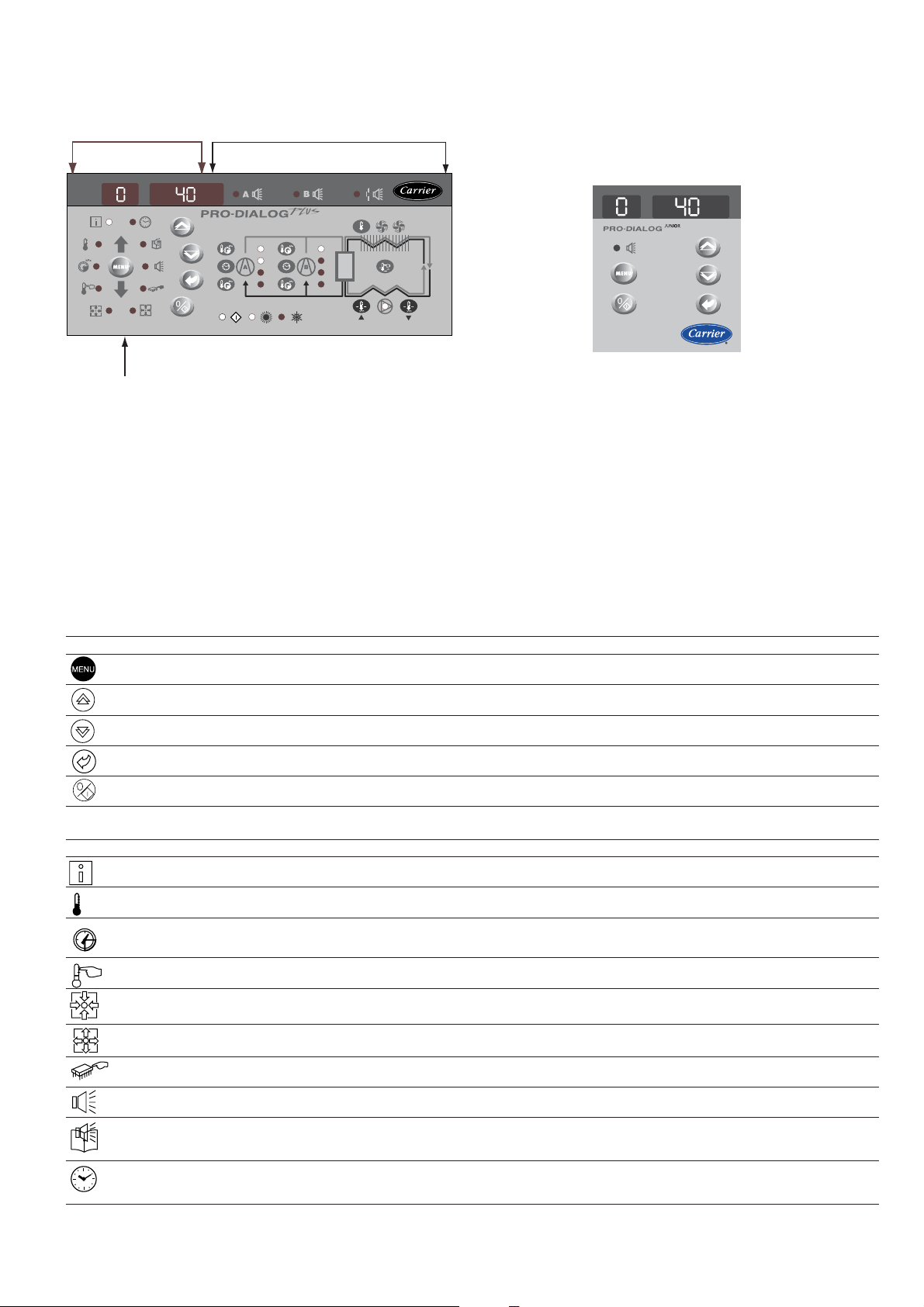
4.1 - Local interface general features
MAIN INTERFACE SUMMARY INTERFACE
MENU BLOCK
PRO-DIALOG PLUS INTERFACE
The local interface enables a number of operating parameters to
be displayed and modified.
• A two-digit display showing the number of the item
selected.
PRO-DIALOG JUNIOR INTERFACE
• A four-digit display showing the contents of the item
The interface consists of two distinct parts: the main interface
(left-hand section) and the summary interface (right-hand section).
selected.
• LEDs and buttons for unit start/stop, menu selection,
menu item selection and value adjustment.
Main interface
It gives access to all PRO-DIALOG data and operating functions.
It consists of:
PRO-DIALOG Junior interface: On some units the local user
interface consists only of a simplified main interface (left-hand
section) that is identical to the main interface described below,
but does not include the menu block diodes.
MAIN INTERFACE
BUTTON NAME DESCRIPTION
Menu Permits the selection of a main menu. Each main menu is represented by an icon. The icon is lit if active.
Up arrow Permits scrolling through the menu items (in the two-digit display). If the modification mode is active this button authorises
Down arrow Permits scrolling through the menu items (in the two-digit display). If the modification mode is active this button authorises
Enter Gives access to the modification mode, validates a modification or displays expanded item description.
Start/stop Authorises start or stop of the chiller in local mode or modification of its operating type.
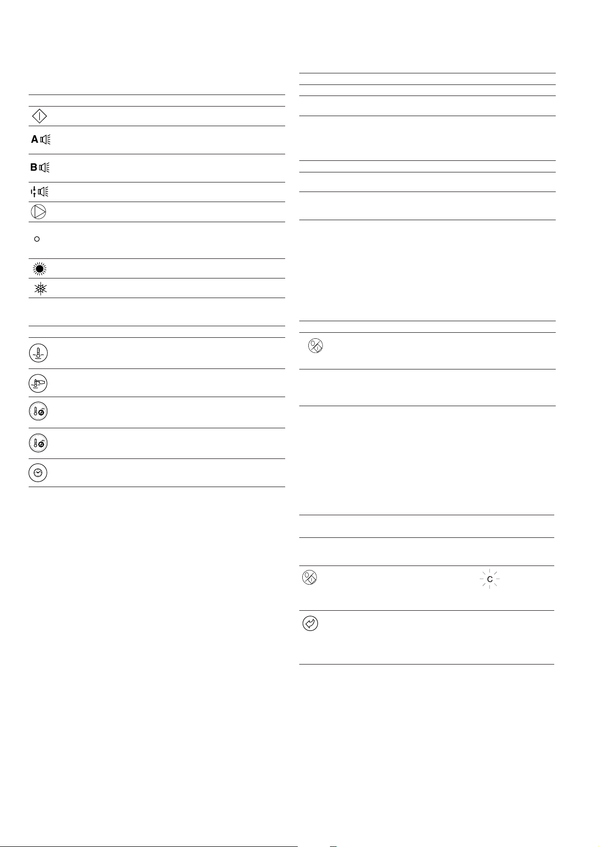
MAIN INTERFACE MENU LED'S
LED* NAME DESCRIPTION INTERFACE DISLAY
INFORMATION menu Displays the general operating parameters for the unit. Information
increase of the value of any parameter.
decrease of the value of any parameter.
TEMPERATURES menu Displays the unit operating temperatures. Temperatures
kPa
* Not available on the PRO-DIALOG Junior interface.
PRESSURES menu Displays the unit operating pressures. Pressures
SETPOINTS menu Displays the unit setpoints and enables them to be modified. Setpoints
INPUTS menu Displays the status of the unit digital and analogue inputs. Inputs
OUTPUTS/TESTS menu Displays the status of the unit outputs and enables them to be tested. Outputs
CONFIGURATIONS menu Displays the unit configuration and enables it to be modified. Confguration
ALARMS menu Displays active alarms. Alarms
ALARMS HISTORY menu Displays the history of the alarms. History
RUNTIMES menu Displays the operating times and number of starts for the unit and the Runtimes
compressors.
9
The summary interface (right hand section) includes a mimic
diagram of the unit, together with push-buttons and LEDs. It
gives quick access to the main operating parameters of the unit.
SUMMARY INTERFACE LEDs*
LED INDICATION WHEN LIT
Green LED:
The unit is authorised to start or is already running
Red LED:
- Lit: circuit A or unit shut down by alarm
- Flashing: circuit A or unit running with alarm present
Red LED:
- Lit: circuit B or unit shut down by alarm
- Flashing: circuit B or unit running with alarm present
Red LED:
Water flow switch default or user safety loc k open.
Green LED:
The evaporator pump is running.
Yellow LEDs:
From top to bottom - start/stop status of compressor A1, A2 and A3
or B1, B2 and B3. Flashing LED indicates that the circuit is in the
protection or defrost mode (A or B).
Green LED:
The unit operates in heating mode.
Green LED:
The unit operates in cooling mode.
* Not available on the PRO-DIALOG Junior interface.
SUMMARY INTERFACE PUSH BUTTONS*
BUTTON DISPLAY
Blue button: evaporator leaving or entering water temperature in °C
Gray button: outdoor air temperature in °C
Control point (setpoint + reset) in °C
Press 1: circuit A/B discharge pressure in kPa
Press 2: circuit A/B saturated condensing temperature in °C
Press 1: circuit A/B suction pressure in kPa
Press 2: circuit A/B saturated suction temperature in °C
Press 1: compressor A1/B1 operating hours in h/10 or h/100
Press 2: compressor A2/B2 operating hours in h/10 or h/100
Press 3: compressor A3/B3 operating hours in h/10 or h/100
* Not available on the PRO-DIALOG Junior interface.
4.2 - Unit start/stop control
4.2.1 - Description
The unit start/stop can be controlled by one of the following
methods:
• Locally on the actual unit (Local control type)
• By remote control with the aid of user contacts (remote
control type)
• By CCN control with the aid of the CCN (CCN control
type)
The main interface includes a Start/Stop button which can be
used to stop or start the unit in the local operating type or to
select the remote or CCN operating type.
The following operating types can be selected using the
Start/Stop button:
OPERATING TYPES
4 DIGIT DISPLA Y DESCRIPTION
LOFF Local Off. The unit is halted in local mode.
L-On Local On. The unit is in local control mode and is
L-Sc* Local On - timer control. The unit is in local control
CCN* CCN. The unit is controlled by CCN commands.
rEM* Remote. The unit is controlled b y remote control
MAST* Master Unit. The unit runs as a master in a two unit
Legend
* Displayed if the configuration requires it.
Section 5.1 gives a more detailed description of the commands to start/stop
the unit, analysed by operating type.
authorised to start.
mode. It is authorised to start if the period is occupied.
If the timer program for unit operation is unoccupied,
the unit remains shut down until the period becomes
occupied.
contacts.
lead/lag arrangement. This is displayed if the unit is
configured for master/slave control.
4.2.2 - Stopping the unit in local mode
The unit can be stopped in local mode at any time by pressing
the Start/Stop button.
TO STOP THE UNIT
BUTTON ACTION 2-DIGIT DISPLAY 4-DIGIT DISPLAY
Press the Start/Stop C LOFF
button for less than
4 seconds (one short
press is enough).
If the button is t LOFF
released, the unit stops
without the need for
further action.
4.2.3 - Starting unit and selecting an operating type
The unit can be started in local mode, or unit operating type
can be changed at any time using the Start/Stop button. In the
example that follows, the unit is stopped (LOFF) and the user
wants to start the unit in local mode.
START UP WITH THE PREVIOUSLY USED OPERA TING TYPE WHEN THE UNIT
IS STOPPED IN LOCAL MODE (LOFF)
BUTTON ACTION
The unit is in local stop mode. The
previously used operating type is local on
(L-ON)
Press the Start/Stop button for 4 seconds
(one short press-down is sufficient). L-ON
illuminates immediately. "C" flashes in the
2-digit display to show that the controller is
awaiting confirmation.
Press the Enter button to confirm the
operating type. "t" is displayed in the 2-digit
display to indicate the operating type
selected. If the Enter button is not pressed
soon enough, the controller will cancel the
change and remain in the stop mode.
2-DIGIT 4-DIGIT
DISPLAY DISPLAY
LOFF
L-On
t L-On
The available operating types are described in the following
table.
10
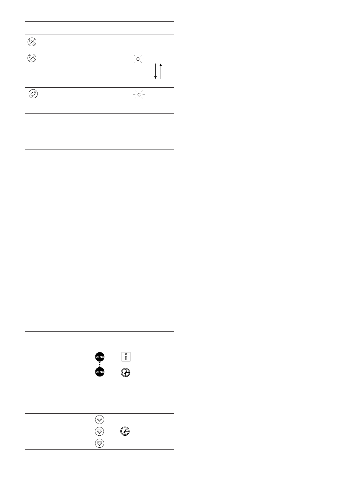
CHANGING THE OPERATING TYPE
BUTTON ACTION
Continually press the operating type
selection button for more than 4 seconds.
Hold down the Start/Stop button.
The available operating types are displayed
one by one until the button is released.
Release the Start/Stop button if the
operating type you want is displayed (in this
example L-On). "C" flashes in the 2-digit
display to show that the controller is
awaiting confirmation.
Press the Enter button to confirm the
operating type selected (in this example:
L-On). "t" is displayed in the 2-digit display
to indicate the operating type selected. If the
Enter button is not pressed soon enough,
the controller will cancel the change and
continue to use the previous operating type.
2-DIGIT 4-DIGIT
DISPLAY DISPLAY
C LOFF
L-On
L-Sc
rEM
L-On
t L-On
4.3 - Menus
4.3.1 - Selecting a menu
The MENU button authorises you to select a menu from the 10
main menus that are available. Each time you press this button
one of the 10 LEDs lights up in turn alongside each of the
icons representing a main menu. The active menu is the one
against which the LED is lit. If a menu is empty then its LED is
not lit. To scroll quickly through the menus, hold the MENU
button down.
4.3.3 - Modifying the value of a parameter/access to a submenu
Press the Enter button for more than 2 seconds to enter the
modification mode or to select a sub-menu. This lets you correct
the value of an item or select a sub-menu with the aid of the up
and down Arrow buttons (if you are authorised to overwrite the
item concerned). When modification mode is activated, the LED
for the main menu to which the item belongs as well as the 2digit display flash in the menu block. Once the required value is
obtained, press the Enter button again to validate the c hange or
to acc e s s t h e sub-m e nu. The LED for the menu to which the
item and the 2-digit display belong then stops flashing,
indicating that modification mode no longer applies.
In modification mode, the value to be modified increases or
decreases in steps of 0.1 every time you press the Arrow
buttons. Holding one of these buttons down increases the rate
of increase or decrease.
NOTE: The access to a sub-menu may require entering a
password. This is automatically requested. See section
4.3.11.2.
The following example shows how to modify the value of item
1 in the Setpoint menu.
4.3.2 - Selecting a menu item
The up and down Arrow buttons let you scroll through the
menu items. Menu item numbers are displayed in the two-digit
display. The item number increases or decreases every time you
press the up or down Arrow button. The menu items that are not
in use or incompatible with the configuration are not displayed.
The value or status associated with the active item is displayed
in the four-digit display. To scroll quickly through the items,
hold the up or down Arrow button down.
The following example shows how to access item 3 in the
Pressures menu.
SELECTING A MENU ITEM
OPERATION PRESS MENU LED ITEM NUMBER
Press the MENU button until the 0
LED marked PRESSURE lights.
Note: On the PRO-DIALOG Junior
interface the menu LEDs are not
available. Instead, each time the
menu button is pressed, the name
of the active menu is dsplayed in
the 4-digit display. In this example,
press the MENU button until
PRESSURE is displayed in the
4-digit display.
BUTTON 2-DIGIT
DISPLAY
kPa
Press one of the Arrow buttons 1
until the two-digit display shows 3
(item number 3).
kPa
2
3
11
Loading...