


30HK040-060 30HL050,060 30HW018-040
Reciprocating Liquid Chillers 50/60 Hz
Installation, Start-Up and
Service Instructions
CONTENTS
Page
GENERAL . . . . . . . . . . . . . . . . . . . . . . . . . . . . . . . . . . . . 2
SAFETY CONSIDERATIONS . . . . . . . . . . . . . . . . . . . . . 2
INSTALLATION . . . . . . . . . . . . . . . . . . . . . . . . . . . . . . 3-25
Location . . . . . . . . . . . . . . . . . . . . . . . . . . . . . . . . . . . . . . 3
Step 1 Ð Inspect Shipment . . . . . . . . . . . . . . . . . . . . . 3
Step 2 Ð Rig the Unit . . . . . . . . . . . . . . . . . . . . . . . . . . 3
·30HK,HL UNITS
·30HW UNITS
Step 3 Ð Place the Unit . . . . . . . . . . . . . . . . . . . . . . . . 3
·30HK,HL UNITS
·30HW UNITS
Step 4 Ð Check Compressor Mounting and Connections . . . . . . . . . . . . . . . . . . . . . . . . . . . . . . . . . . 3
Step 5 Ð Make Piping Connections . . . . . . . . . . . . . 13
·30HK,HWC,HWS CONDENSER DESCRIPTION
·30HL,HWA SYSTEM CONDENSER
·30HWB CONDENSER DESCRIPTION
·30HK,HWC,HWS CONDENSER(S)
·30HWB CONDENSER
·30HK,HWB,HWC,HWS UNITS
·COOLER DESCRIPTION
·COOLER PIPING
Step 6 Ð Make Electrical Connections . . . . . . . . . . . 19
·30HK,HL UNITS
·30HW UNITS
·ALL UNITS
PRE-START-UP . . . . . . . . . . . . . . . . . . . . . . . . . . . . . 25-27
Initial Check . . . . . . . . . . . . . . . . . . . . . . . . . . . . . . . . . 25
Check Refrigerant Charge . . . . . . . . . . . . . . . . . . . . . 26
· LIQUID CHARGING METHOD
Check Oil Charge . . . . . . . . . . . . . . . . . . . . . . . . . . . . . 27
·TO ADD OIL
·TO REMOVE OIL
START-UP AND OPERATION . . . . . . . . . . . . . . . . . . 27-30
Operation Checks . . . . . . . . . . . . . . . . . . . . . . . . . . . . 27
Operating Limitations . . . . . . . . . . . . . . . . . . . . . . . . . 27
·HIGH COOLER LEAVING CHILLED WATER (FLUID) TEMPERATURES (LCWT)
·LOW COOLER LCWT
·MAIN POWER SUPPLY
Check Refrigerant Feed Components . . . . . . . . . . . . 27
·THERMOSTATIC EXPANSION VALVE (TXV)
·FILTER DRIER
·MOISTURE-LIQUID INDICATOR
·LIQUID LINE SERVICE VALVE
·DISCHARGE LINE CHECK VALVE
·HOT GAS BYPASS VALVE
·LIQUID LINE SOLENOID VALVE (30HL ONLY)
·PRESSURE RELIEF DEVICES
Compressor and Unit Protective Devices . . . . . . . . . 28
· CIRCUIT BREAKER
·COMPRESSOR INTERNAL THERMAL PROTECTION
·CRANKCASE HEATER
·OIL PRESSURE SAFETY SWITCH (OPS)
Check Unit Safeties . . . . . . . . . . . . . . . . . . . . . . . . . . . 28
·CONTROL MODULE
·HIGH-PRESSURE SWITCH
·LOW-PRESSURE SWITCH
·CHILLED FLUID TEMPERATURE CONTROLLER
·FREEZE-UP PROTECTION
·LOSS-OF-COOLER-FLOW PROTECTION
·COMPRESSOR GROUND FAULT SENSOR
UNIT OPERATION . . . . . . . . . . . . . . . . . . . . . . . . . . . 30-32
Capacity Control and Operating Sequence . . . . . . . 30
·30HK,HL UNITS
·30HW UNITS
SERVICE . . . . . . . . . . . . . . . . . . . . . . . . . . . . . . . . . . 32-35
Compressor Replacement . . . . . . . . . . . . . . . . . . . . . . 32
Circuit Breaker(s) . . . . . . . . . . . . . . . . . . . . . . . . . . . . . 32
Brazed-Plate Cooler and Condenser
Heat Exchanger Replacement . . . . . . . . . . . . . . . . . 32
Brazed-Plate Cooler and Condenser
Heat Exchanger Cleaning . . . . . . . . . . . . . . . . . . . . . 32
Shell-and-Tube Condenser Cleaning . . . . . . . . . . . . . 32
Thermistor . . . . . . . . . . . . . . . . . . . . . . . . . . . . . . . . . . . 33
·THERMISTOR REPLACEMENT, 30HK,HL UNITS
·THERMISTOR REPLACEMENT, 30HW UNITS
SERVICING COOLER (30HK,HL ONLY) . . . . . . . . . 36,37
Tube Plugging . . . . . . . . . . . . . . . . . . . . . . . . . . . . . . . 36
· RETUBING
Tightening Cooler Head Bolts . . . . . . . . . . . . . . . . . . 36
·GASKET PREPARATION
·BOLT TORQUES
TROUBLESHOOTING . . . . . . . . . . . . . . . . . . . . . . . . 37-39
Complete Unit Stoppage and Restart . . . . . . . . . . . . 37
·GENERAL POWER FAILURE
·UNIT ON-OFF SWITCH IS OPEN
·CONTACTS OF ANY AUXILIARY INTERLOCKS ARE OPEN
·CHILLED FLUID PROOF-OF-FLOW SWITCH(ES) OPEN
·OPEN LOW-PRESSURE SWITCH
·TEMPERATURE CONTROLLER SHUTS UNIT DOWN ON OUT-OF-RANGE
·OPEN HIGH-PRESSURE SWITCH(ES)
·OPEN COMPRESSOR INTERNAL THERMAL PROTECTION
·OPEN OIL PRESSURE SWITCH
·OPEN CONTACTS ON COMPRESSOR GROUNDCURRENT SENSOR(S) (Accessory)
·OPEN 24-V CONTROL CIRCUIT BREAKER(S)
·COOLING LOAD SATISFIED
·THERMISTOR FAILURE
START-UP CHECKLIST FOR
CHILLER SYSTEMS . . . . . . . . . . . . . . . . . . . CL-1 to CL-4
Manufacturer reserves the right to discontinue, or change at any time, speci®cations or designs without notice and without incurring obligations.
Book |
2 |
|
PC 903 |
Catalog No. 533-070 |
Printed in U.S.A. |
Form 30H-10SI |
Pg 1 |
11-98 |
Replaces: 30H-8SI |
Tab |
5c |
|
|
|
|
|
|
|
|
|
|
|
|
|
|
|
|
|
|
GENERAL
These installation instructions cover the 30HK, HL, HWA, HWB, HWC, and HWS units. The HL and HWA are condenserless units, and the HK, HWB, HWC, and HWS units are all ¯uid cooled. In addition, the 30HK and HWC units have a standard mechanically cleanable condenser and the 30HWS unit has a mechanically cleanable condenser speci®cally designed for sea coast applications.
SAFETY CONSIDERATIONS
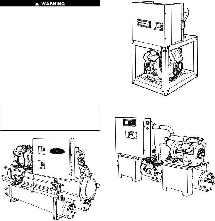
Installing, starting up, and servicing this equipment (Fig. 1-3) can be hazardous due to system pressures, electrical components, and equipment location (roofs, elevated structures, etc.).
Only trained, quali®ed installers and service technicians should install, start up, and service this equipment.
When working on the equipment, observe precautions in the literature and on tags, stickers, and labels attached to the equipment.
·Follow all safety codes.
·Wear safety glasses and work gloves.
·Use care in handling, rigging, and setting bulky
equipment. |
Fig. 2 Ð 30HWA,B Unit |
Be sure all power to equipment is shut off before performing maintenance or service. There may be more than one disconnect. Tag all disconnects to alert others not to turn on power until work is completed.
Fig. 3 Ð 30HWC,S Unit
Fig. 1 Ð 30HK,HL Unit (30HK Shown)
2

INSTALLATION
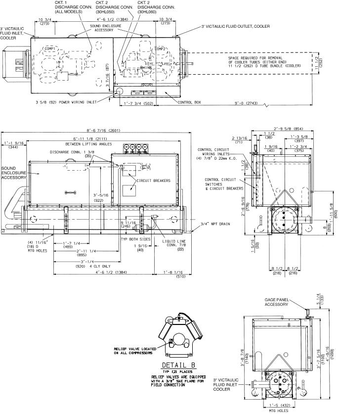
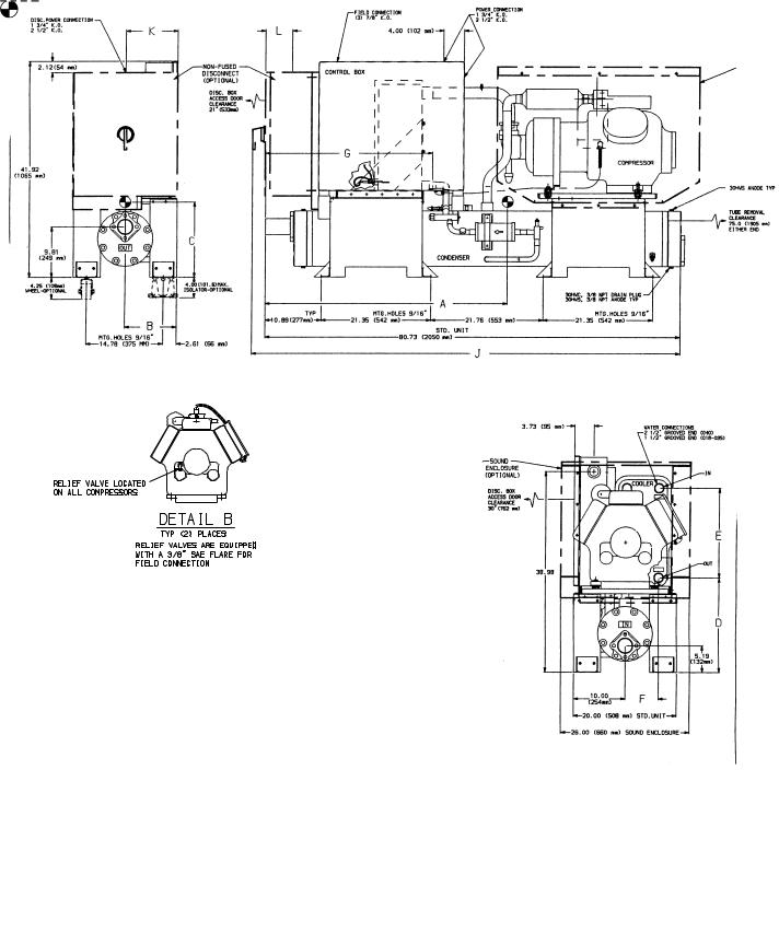
Location Ð Do not store units in an area exposed to weather because of sensitive control mechanisms and electronic devices. Locate unit indoors. See Fig. 4-8 for unit dimensional details.
Allow 36 in. (914 mm) in front of the unit for control box access door. Compressor can be removed from either side or the front of the unit. Prior to installation determine which direction compressor will be removed, and leave 3 to 4 ft (914 to 1219 mm) clearance for removal.
On 30HK,HL units leave 71¤2 ft (2.3 m) (for 040 units) or 9 ft (2.7 m) (for 050,060 units) clearance on one side for cooler tube removal. Leave 2 ft (610 mm) clearance on the other side for making ¯uid connections to cooler and water connections to condenser. See Fig. 4 and 5.
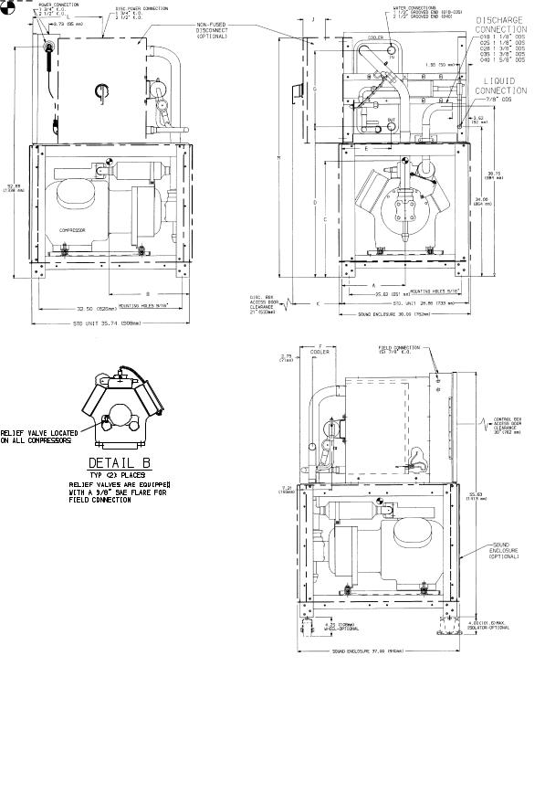
On 30HWA,B units, leave 2 ft (610 mm) on one side for making ¯uid connections to cooler and water connections to condenser, accessing the thermostatic expansion valve (TXV), and replacing heat exchanger(s) if necessary. See Fig. 6 and 7.
On 30HWC,S units, leave 75 in. (1905 mm) on one side for condenser tube removal and 2 ft (610 mm) on the other side for making ¯uid connections to cooler and water connections to condenser, accessing the TXV, and replacing heat exchanger(s) if necessary. See Fig. 8.
The ¯oor must be strong enough to support the unit operating weight (see Tables 1A-2B and Fig. 9 and 10). If necessary, add a supporting structure (steel beams or reinforced concrete slabs) to the ¯oor to transfer weight to nearest beams.
Additional weights of factory-installed options (30HW only) are:
Sound enclosure Ð 75 lb (34 kg) Hot gas bypass Ð 15 lb (7 kg)
80-amp non-fused disconnect Ð 15 lb (6.8 kg) 100-amp non-fused disconnect Ð 25 lb (11.3 kg) 200-amp non-fused disconnect Ð 70 lb (31.8 kg)
Be sure interconnecting piping and electrical conduits are suspended freely, and are not in contact with any adjacent walls. Be sure unit capillaries are not rubbing against anything.
Step 1 Ð Inspect Shipment Ð Inspect unit for damage or missing parts. If damaged, or if shipment is incomplete, ®le a claim immediately with the shipping company.
Step 2 Ð Rig and Place Unit
30HK,HL UNITS Ð On each end of cooler, a steel loop is provided for the preferred method of lifting unit. Use spreader bars to keep cables away from compressor enclosure and control box. If unit is to be moved by forklift truck, use one of the following two methods:
1.From front or rear, lift under the cooler rails. Unit can be either on or off skid.
2.When moving from the ends, leave unit on the skid. Lift from under the skid.
If unit is to be dragged into ®nal position, or moved on rollers, it is recommended that it be left on the skid. When dragging or rolling, apply force only to the skid, not to the unit. Lift from above, using the lifting angles provided, to remove unit from the skid.
30HW UNITS
NOTE: If accessory mobility package (Carrier part no. 30HW900008) is to be used, install this accessory after bringing unit into building and before moving the unit to its ®nal location per installation instructions provided with the accessory.
Units Equipped With Factory-Installed Unit Wheels Ð This factory-installed option consists of 4 swivel-type wheels mounted to the legs of the unit. See Fig. 11. For units equipped with this option, leave the skid on until the unit is in the building. Once in the building, remove the skid, and wheel the unit to its ®nal location.
NOTE: The wheels are equipped with a thumb-screw brake.
Units Not Equipped With Factory-Installed Unit Wheels Ð Do not remove the skid until the unit has been moved to its ®nal location. The unit may be moved by means of rollers under the skid, a forklift truck, or rig and slings.
Step 3 Ð Place the Unit
30HK,HL UNITS Ð When unit is in ®nal position, remove skid, level the unit (using a level), and bolt the unit to ¯oor or pad.
NOTE: These units are not suitable for unprotected outdoor use.
Carrier recommends that these units be located in the basement or on the ground ¯oor. However, if it is necessary to locate the unit on an upper ¯oor, be sure the structure has been designed to support the unit weight. If necessary, add structural support to ¯oor. Also, be sure the surface for installation is level. Refer to Fig. 4 and 5 for space requirements and Fig. 9 for weight distribution.
Only electrical power connections, water connections for condenser, and ¯uid connections for cooler are required for 30HK installation. Installation of 30HL units varies only in ®eld piping required for the remote condenser.
30HW UNITS Ð When the unit is in its ®nal position, remove the skid (from units not equipped with factorymounted wheels), or remove the wheels (if equipped). Remove 3¤8-in. wheel nuts to remove wheels from unit legs. Level the unit (using a level), and bolt the unit to the ¯oor or pad.
If unit is to be mounted on unit external vibration isolators, follow the mounting instructions included with the accessory vibration isolator (Carrier part numbers 30HW900001 and -002).
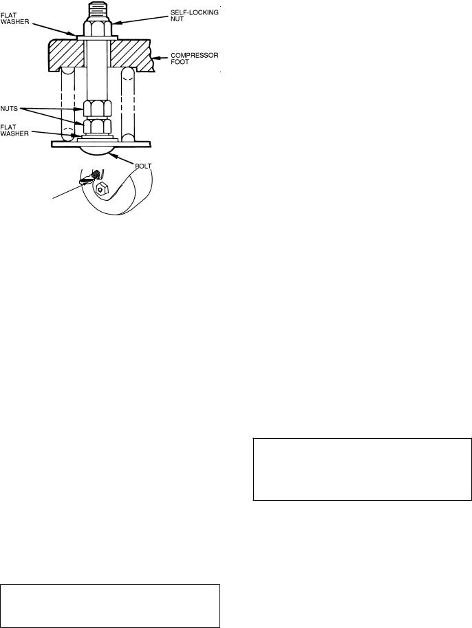
Step 4 Ð Check Compressor Mounting and Connections Ð As shipped, the compressor is held down by special self-locking nuts (Fig. 12). After unit is installed, loosen the self-locking nuts one at a time until compressor ¯oats freely. Do not remove nuts, as they are self-locking and will hold their locked position.
3

TOP VIEW
|
|
|
|
FRONT VIEW |
RIGHT SIDE VIEW |
|
UNIT |
|
DIMENSIONS Ð in. (mm) |
|
|
||
30HK |
A |
B |
C |
D |
|
|
|
040 |
51¤4 |
90 |
149¤16 |
715¤16 |
|
|
(133) |
(2286) |
(370) |
(202) |
|
|
|
|
|
||||
050,060 |
103¤4 |
108 |
201¤16 |
139¤16 |
|
|
(273) |
(2743) |
(510) |
(344) |
|
||
|
|
|
||||
|
|
|
LEGEND |
|
|
|
COMP Ð Compressor |
|
|
|
|||
K.O. |
Ð |
Knockout |
|
|
|
|
MTG |
Ð Mounting |
|
|
|
|
|
SAE |
Ð Society of Automotive Engineers (U.S.A.) |
|
||||
NOTES:
1.Standard unit shown with the sound enclosure accessory.
2.Dimensions are in inches unless otherwise indicated.
Dimensions in ( ) are in millimeters.
3. Service clearance for the control box is 36-in.
LEFT SIDE VIEW
Fig. 4 Ð 30HK040-060 (Fluid Cooled)
4
TOP VIEW
FRONT VIEW |
RIGHT SIDE VIEW |
|
LEGEND |
CLY |
Ð Cylinder |
COMP |
Ð Compressor |
CONN |
Ð Connection |
K.O. |
Ð Knockout |
NOTES:
1. Standard unit shown with the sound enclosure accessory.
2. Dimensions are in inches unless otherwise indicated. Dimensions in ( ) are in millimeters.
LEFT SIDE VIEW
Fig. 5 Ð 30HL050,060 (Condenserless)
5
REAR VIEW
LEFT SIDE VIEW
UNIT |
|
|
DIMENSIONS Ð in. (mm) |
|
|
|||
30HWA |
A |
B |
C |
D |
E |
F |
G |
|
018 |
12.58 |
19.20 |
20.48 |
33.85 |
11.72 |
5.75 |
17.95 |
|
(320) |
(488) |
(520) |
(860) |
(298) |
(146) |
(456) |
||
|
||||||||
025 |
12.82 |
18.98 |
20.57 |
33.85 |
11.72 |
5.75 |
17.95 |
|
(326) |
(482) |
(522) |
(860) |
(298) |
(146) |
(456) |
||
|
||||||||
028 |
12.64 |
18.31 |
20.73 |
33.85 |
11.72 |
5.75 |
17.95 |
|
(321) |
(465) |
(527) |
(860) |
(298) |
(146) |
(456) |
||
|
||||||||
035 |
12.87 |
18.62 |
20.81 |
33.85 |
11.72 |
5.75 |
17.95 |
|
(327) |
(473) |
(529) |
(860) |
(298) |
(146) |
(456) |
||
|
||||||||
040 |
12.66 |
18.64 |
21.30 |
34.15 |
11.34 |
8.22 |
17.36 |
|
(322) |
(473) |
(541) |
(867) |
(288) |
(209) |
(441) |
||
|
||||||||
|
|
|
|
|
|
|
RIGHT SIDE VIEW |
|
||
DISCONNECT |
|
LOCATION Ð in. (mm) |
|
|
MODEL 30HWA (See Table Below) |
|
||||
(Amps) |
J |
K |
L |
M |
018--- |
025--- |
|
028--- |
035--- |
040--- |
80 |
3.33 |
2.98 |
14.44 |
46.50 |
100,200, |
100,200, |
|
100,200, |
100,600,900 |
Ð |
(85) |
(76) |
(367) |
(1181) |
600,800,900 |
600,900 |
|
600,900 |
|||
|
|
|
|
|||||||
100 |
4.33 |
4.98 |
14.82 |
47.50 |
500 |
500,800 |
|
800 |
200,800 |
100,200, |
(110) |
(126) |
(376) |
(1207) |
|
600,900 |
|||||
|
|
|
|
|
|
|||||
200 |
7.46 |
11.19 |
15.82 |
54.50 |
Ð |
Ð |
|
500 |
500 |
500,800 |
(189) |
(284) |
(402) |
(1384) |
|
||||||
|
|
|
|
|
|
|
||||
|
LEGEND |
NOTES: |
|
DISC. Ð |
Disconnect |
1. |
Denotes center of gravity. |
K.O. Ð |
Knockout |
2. |
Denotes accessory or factory-installed option. |
|
|
||
|
|
3. |
Dimensions are in inches. Dimensions in ( ) are in millimeters. |
Fig. 6 Ð 30HWA018-040 (Condenserless)
MODEL |
VOLT-Hz |
100 |
575-60 |
200 |
380-60 |
500 |
208/230-60 |
600 |
460-60 |
800 |
230-50 |
900 |
400-50 |
|
|
6
REAR VIEW
LEFT SIDE VIEW
UNIT |
|
|
|
|
|
|
DIMENSIONS Ð in. (mm) |
|
|
|
|
|
|
|
|
|
|
|
|
|||||||
30HWB |
|
A |
B |
|
C |
|
|
D |
|
E |
F |
|
|
G |
|
H |
|
J |
|
|
|
|
|
|||
018 |
|
13.14 |
18.72 |
|
22.02 |
|
33.85 |
|
11.72 |
5.75 |
|
12.29 |
|
17.95 |
9.28 |
|
|
|
|
|
|
|||||
|
(334) |
(475) |
|
(559) |
|
(860) |
|
(298) |
(146) |
|
(312) |
|
(456) |
(236) |
|
|
|
|
|
|
||||||
|
|
|
|
|
|
|
|
|
|
|
|
|
||||||||||||||
025 |
|
13.22 |
18.25 |
|
22.10 |
|
33.85 |
|
11.72 |
5.75 |
|
12.29 |
|
17.95 |
9.28 |
|
|
|
|
|
|
|||||
|
(336) |
(464) |
|
(561) |
|
(860) |
|
(298) |
(146) |
|
(312) |
|
(456) |
(236) |
|
|
|
|
|
|
||||||
|
|
|
|
|
|
|
|
|
|
|
|
|
||||||||||||||
028 |
|
13.18 |
17.71 |
|
22.39 |
|
33.85 |
|
11.72 |
5.75 |
|
12.29 |
|
17.95 |
9.28 |
|
|
|
|
|
|
|||||
|
(335) |
(450) |
|
(569) |
|
(860) |
|
(298) |
(146) |
|
(312) |
|
(456) |
(236) |
|
|
|
|
|
|
||||||
|
|
|
|
|
|
|
|
|
|
|
|
|
||||||||||||||
035 |
|
13.45 |
17.98 |
|
22.68 |
|
33.85 |
|
11.72 |
5.75 |
|
12.29 |
|
17.95 |
9.28 |
|
|
|
|
|
|
|||||
|
(342) |
(457) |
|
(576) |
|
(860) |
|
(298) |
(146) |
|
(312) |
|
(456) |
(236) |
|
|
|
|
|
|
||||||
|
|
|
|
|
|
|
|
|
|
|
|
|
||||||||||||||
040 |
|
13.27 |
17.75 |
|
23.44 |
|
34.15 |
|
11.34 |
8.22 |
|
12.38 |
|
17.36 |
8.22 |
|
|
|
|
|
|
|||||
|
(337) |
(451) |
|
(595) |
|
(867) |
|
(288) |
(209) |
|
(314) |
|
(441) |
(209) |
|
|
|
|
|
|
||||||
|
|
|
|
|
|
|
|
RIGHT SIDE VIEW |
|
|
||||||||||||||||
|
|
|
|
|
|
|
|
|
|
|
|
|
|
|
|
|
|
|
|
|
|
|
|
|||
|
|
|
|
|
|
|
|
|
|
|
|
|
|
|
|
|
|
|
||||||||
DISCONNECT |
|
|
|
|
|
|
LOCATION Ð in. (mm) |
|
|
|
|
|
MODEL 30HWB (See Table Below) |
|
||||||||||||
(Amps) |
|
|
|
K |
|
|
L |
|
|
M |
|
|
|
N |
|
018--- |
025--- |
028--- |
|
035--- |
040--- |
|||||
|
80 |
|
|
3.33 |
|
2.98 |
|
|
14.44 |
|
|
|
46.50 |
|
100,200,300, |
100,200, |
100,200, |
|
100,200, |
100 |
||||||
|
|
|
(85) |
|
|
(76) |
|
|
(367) |
|
|
|
(1181) |
|
600,800,900 |
600,900 |
600,900 |
|
600,900 |
|||||||
|
|
|
|
|
|
|
|
|
|
|
|
|
|
|||||||||||||
|
100 |
|
|
4.33 |
|
4.98 |
|
|
14.82 |
|
|
|
47.50 |
|
500 |
500,800 |
500,800 |
|
800 |
200, |
||||||
|
|
|
(110) |
|
|
(126) |
|
|
(376) |
|
|
|
(1207) |
|
|
600,900 |
||||||||||
|
|
|
|
|
|
|
|
|
|
|
|
|
|
|
|
|
|
|||||||||
|
200 |
|
|
7.46 |
|
11.19 |
|
|
15.82 |
|
|
|
54.50 |
|
Ð |
Ð |
Ð |
|
500 |
500,800 |
||||||
|
|
|
(189) |
|
|
(284) |
|
|
(402) |
|
|
|
(1384) |
|
|
|||||||||||
|
|
|
|
|
|
|
|
|
|
|
|
|
|
|
|
|
|
|
||||||||
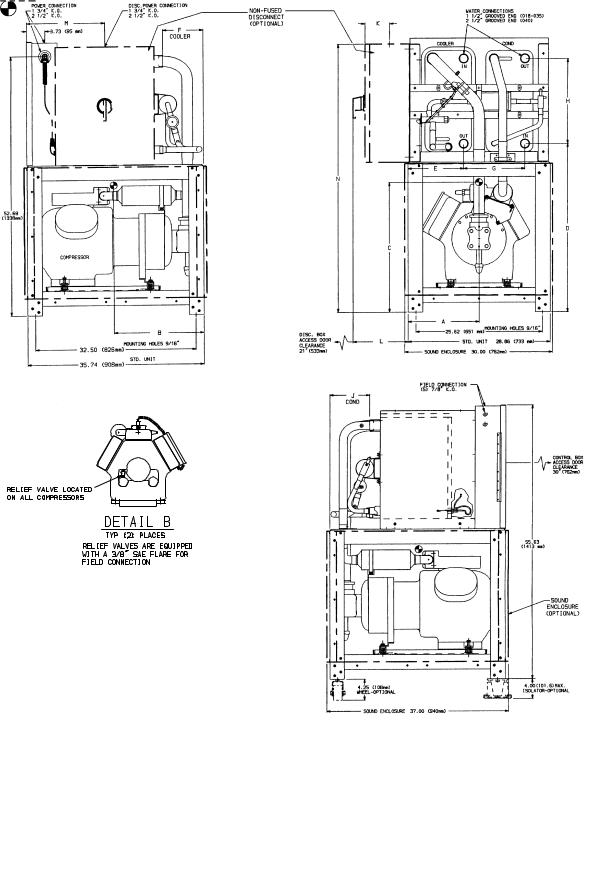
LEGEND
COND Ð Condenser
DISC. Ð Disconnect
K.O. Ð Knockout
NOTES: |
MODEL |
VOLT-Hz |
|
|
|
||
1. |
Denotes center of gravity. |
100 |
575-60 |
2. |
Denotes accessory or factory-installed option. |
200 |
380-60 |
3. |
Dimensions are in inches. Dimensions in ( ) are in millimeters. |
500 |
208/230-60 |
|
|
600 |
460-60 |
|
|
800 |
230-50 |
|
|
900 |
400-50 |
|
|
|
|
Fig. 7 Ð 30HWB018-040 (Fluid Cooled)
7
LEFT SIDE VIEW |
FRONT VIEW |
UNIT |
|
|
|
|
DIMENSIONS Ð in. (mm) |
|
|
|
|
|
|
|
|
|
|||||
30HWC,S |
|
A |
B |
|
C |
|
D |
E |
F |
|
G |
|
|
|
|
|
|||
018 |
|
47.50 |
|
9.90 |
14.00 |
|
18.15 |
|
17.95 |
6.69 |
|
34.20 |
|
|
|
|
|
||
|
(1206) |
|
(251) |
(356) |
|
(461) |
|
(456) |
(170) |
|
(869) |
|
|
|
|
|
|||
|
|
|
|
|
|
|
|
|
|
|
|||||||||
025 |
|
48.30 |
|
9.90 |
15.50 |
|
18.15 |
|
17.95 |
6.69 |
|
34.20 |
|
|
|
|
|
||
|
(1227) |
|
(251) |
(394) |
|
(461) |
|
(456) |
(170) |
|
(869) |
|
|
|
|
|
|||
|
|
|
|
|
|
|
|
|
|
|
|||||||||
028 |
|
48.00 |
|
10.00 |
15.80 |
|
18.15 |
|
17.95 |
6.69 |
|
34.20 |
|
|
|
|
|
||
|
(1219) |
|
(254) |
(401) |
|
(461) |
|
(456) |
(170) |
|
(869) |
|
|
|
|
|
|||
|
|
|
|
|
|
|
|
|
|
|
|||||||||
035 |
|
48.20 |
|
10.00 |
15.90 |
|
18.15 |
|
17.95 |
6.69 |
|
34.20 |
|
|
|
|
|
||
|
(1224) |
|
(254) |
(404) |
|
(461) |
|
(456) |
(170) |
|
(869) |
|
|
|
|
|
|||
|
|
|
|
|
|
|
|
|
|
|
|||||||||
040 |
|
47.80 |
|
10.00 |
15.90 |
|
18.45 |
|
17.36 |
6.40 |
|
32.94 |
|
|
|
|
|
||
|
(1214) |
|
(254) |
(404) |
|
(469) |
|
(441) |
(163) |
|
(837) |
|
|
|
|
|
|||
|
|
|
|
|
|
|
|
RIGHT SIDE VIEW |
|
||||||||||
|
|
|
|
|
|
|
|
|
|
|
|
|
|
|
|
|
|
||
|
|
|
|
|
|
|
|
|
|
|
|
|
|
|
|
|
|
||
|
|
|
|
|
|
|
|
|
|
|
|
|
|
|
|||||
DISCONNECT |
|
|
LOCATION Ð in. (mm) |
|
|
|
|
|
MODEL 30HWC,S (See Table Below) |
|
|||||||||
(Amps) |
|
|
J |
|
|
|
K |
|
L |
|
|
018--- |
|
025--- |
028--- |
035--- |
040--- |
||
80 |
|
|
|
77.61 |
|
|
4.38 |
|
3.33 |
|
|
100,200, |
|
100,200, |
100,200, |
100,200, |
100 |
||
|
|
|
(1971) |
|
|
(111) |
|
(85) |
|
|
600,800,900 |
600,900 |
600,900 |
600,900 |
|||||
|
|
|
|
|
|
|
|
|
|
||||||||||
100 |
|
|
|
79.61 |
|
|
5.00 |
|
4.33 |
|
|
500 |
|
500,800 |
500,800 |
800 |
200, |
||
|
|
|
(2022) |
|
|
(127) |
|
(110) |
|
|
|
600,900 |
|||||||
|
|
|
|
|
|
|
|
|
|
|
|
|
|
|
|||||
200 |
|
|
|
83.74 |
|
|
10.00 |
|
7.46 |
|
|
Ð |
|
Ð |
Ð |
500 |
500,800 |
||
|
|
|
(2127) |
|
|
(254) |
|
(189) |
|
|
|
||||||||
|
|
|
|
|
|
|
|
|
|
|
|
|
|
|
|
||||
|
|
|
|
|
|
|
|
|
|
|
|
|
|
|
|
|
|
|
|
LEGEND
D. Ð Diameter
Disc. Ð Disconnect
K.O. Ð Knockout
SCH.40 Ð Schedule 40 Pipe
NOTES: |
MODEL |
VOLT-Hz |
|
|
|
||
1. |
Denotes center of gravity. |
100 |
575-60 |
2. |
Denotes accessory or factory-installed option. |
200 |
380-60 |
3. |
Dimensions are in inches. Dimensions in ( ) are in millimeters. |
500 |
208/230-60 |
|
|
600 |
460-60 |
|
|
800 |
230-50 |
|
|
900 |
400-50 |
|
|
|
|
Fig. 8 Ð 30HWC,S018-040 (Fluid Cooled)
8
WEIGHT DISTRIBUTION AT EACH MOUNTING HOLE, 60 HZ UNITS
|
|
|
|
|
|
|
|
|
|
|
MOUNTING HOLES |
|
|
|
|
|
|
|
|
|
|
||||
UNIT |
|
|
|
|
|
30HK |
|
|
|
|
|
|
|
|
|
|
|
30HL |
|
|
|
|
|||
SIZE |
|
A |
B |
|
|
C |
|
D |
|
A |
|
B |
|
C |
|
|
D |
||||||||
|
Lb |
|
Kg |
Lb |
|
Kg |
Lb |
|
Kg |
Lb |
|
Kg |
Lb |
|
Kg |
|
Lb |
|
Kg |
Lb |
|
Kg |
Lb |
|
Kg |
040 |
710 |
|
322 |
712 |
|
323 |
705 |
|
320 |
703 |
|
319 |
Ð |
|
Ð |
Ð |
|
Ð |
Ð |
Ð |
|
Ð |
Ð |
|
|
050 |
787 |
|
357 |
789 |
|
358 |
782 |
|
355 |
780 |
|
354 |
519 |
|
235 |
|
521 |
|
236 |
516 |
|
234 |
514 |
|
233 |
060 |
838 |
|
380 |
840 |
|
381 |
832 |
|
377 |
830 |
|
376 |
534 |
|
242 |
|
536 |
|
243 |
531 |
|
241 |
529 |
|
240 |
NOTE: See Fig. 4 and 5 for speci®c mounting hole location dimensions.
WEIGHT DISTRIBUTION AT EACH MOUNTING HOLE, 50 HZ UNITS
|
|
|
|
|
|
|
|
|
|
|
MOUNTING HOLES |
|
|
|
|
|
|
|
|
|
|
||||
UNIT |
|
|
|
|
|
30HK |
|
|
|
|
|
|
|
|
|
|
|
30HL |
|
|
|
|
|||
SIZE |
|
A |
B |
|
|
C |
|
D |
|
A |
|
B |
|
C |
|
|
D |
||||||||
|
Lb |
|
Kg |
Lb |
|
Kg |
Lb |
|
Kg |
Lb |
|
Kg |
Lb |
|
Kg |
|
Lb |
|
Kg |
Lb |
|
Kg |
Lb |
|
Kg |
040 |
721 |
|
327 |
723 |
|
328 |
716 |
|
325 |
715 |
|
325 |
Ð |
|
Ð |
Ð |
|
Ð |
Ð |
Ð |
|
Ð |
Ð |
|
|
050 |
838 |
|
380 |
840 |
|
381 |
832 |
|
377 |
830 |
|
376 |
534 |
|
242 |
|
526 |
|
238 |
531 |
|
241 |
529 |
|
240 |
060 |
853 |
|
387 |
855 |
|
388 |
847 |
|
384 |
845 |
|
383 |
550 |
|
249 |
|
551 |
|
250 |
545 |
|
247 |
544 |
|
247 |
|
|
|
|
|
|
|
|
|
|
|
|
|
|
|
|
|
|
|
|
|
|
|
|
|
|
NOTE: See Fig. 4 and 5 for speci®c mounting hole location dimensions.
LOCATION OF MOUNTING HOLES
Fig. 9 Ð Weight Distribution and Mounting Hole Location; 30HK,HL Units
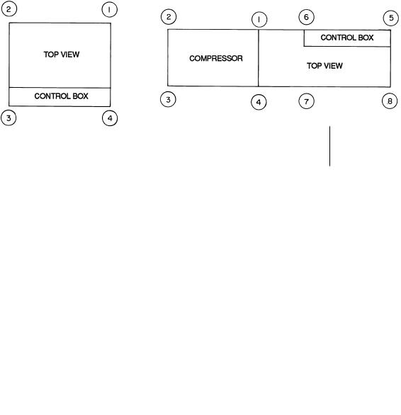
|
30HWA,B |
|
|
|
|
|
|
30HWC,S |
|
|
|||
|
|
WEIGHT DISTRIBUTION AT EACH MOUNTING HOLE Ð Lb (kg) |
|
|
|||||||||
|
|
|
|
|
|
|
|
|
|
|
|
|
|
UNIT |
|
|
|
|
|
|
MOUNTING HOLE NO. |
|
|
||||
30HW |
|
1 |
2 |
|
|
3 |
4 |
5 |
|
6 |
|
7 |
8 |
A018 |
|
|
185 |
(83.9) |
|
|
|
Ð |
|
|
|||
A025 |
|
|
220 |
(99.8) |
|
|
|
Ð |
|
|
|||
A028 |
|
|
240 (108.9) |
|
|
|
Ð |
|
|
||||
A035 |
|
|
244 (110.7) |
|
|
|
Ð |
|
|
||||
A040 |
|
|
270 (122.5) |
|
|
|
Ð |
|
|
||||
B018 |
|
|
199 |
(90.3) |
|
|
|
Ð |
|
|
|||
B025 |
|
|
238 (108.0) |
|
|
|
Ð |
|
|
||||
B028 |
|
|
266 (120.7) |
|
|
|
Ð |
|
|
||||
B035 |
|
|
271 (122.9) |
|
|
|
Ð |
|
|
||||
B040 |
|
|
328 (148.8) |
|
|
|
Ð |
|
|
||||
C,S018 |
|
|
171 |
(77.6) |
|
|
|
136 (61.7) |
|
|
|||
C,S025 |
|
|
196 |
(88.9) |
|
|
|
144 (65.3) |
|
|
|||
C,S028 |
|
|
211 |
(95.7) |
|
|
|
160 (72.6) |
|
|
|||
C,S035 |
|
|
216 |
(98.0) |
|
|
|
161 (73.0) |
|
|
|||
C,S040 |
|
|
240 (108.9) |
|
|
|
185 (83.9) |
|
|
||||
|
|
|
|
|
|
|
|
|
|
|
|
|
|
Fig. 10 Ð Mounting Hole Weight Distribution; 30HW Units
9
Table 1A Ð Physical Data; 30HK, HWB, HWC, and HWS Fluid-Cooled Units Ð English
UNIT 30 |
HW-018* |
HW-025* |
HW-028* |
HW-035* |
HW-040* |
|
HK040 |
HK050 |
HK060 |
|
OPERATING WT (Approximate) − lb |
|
|
|
|
|
|
|
|
|
|
|
HWB |
795 |
950 |
1065 |
1085 |
1310 |
|
Ð |
Ð |
Ð |
|
HWC,S |
1231 |
1358 |
1484 |
1508 |
1702 |
|
Ð |
Ð |
Ð |
|
HK |
Ð |
Ð |
Ð |
Ð |
Ð |
|
2830/ |
3138/ |
3340/ |
|
|
2875² |
3340² |
3400² |
||||||
|
|
|
|
|
|
|
|
|||
REFRIGERANT Ð lb |
|
|
|
|
R-22 |
|
|
|
|
|
|
HWB |
12.5 |
15.0 |
17.5 |
18.5 |
23.2 |
|
Ð |
Ð |
Ð |
|
HWC,S |
35.0 |
37.0 |
42.0 |
42.0 |
47.0 |
|
Ð |
Ð |
Ð |
|
HK Ð Ckt 1 |
Ð |
Ð |
Ð |
Ð |
Ð |
|
35/40² |
45/45² |
45/45² |
|
HK − Ckt 2 |
Ð |
Ð |
Ð |
Ð |
Ð |
|
35/35² |
35/45² |
45/45² |
|
COMPRESSOR |
|
|
|
|
|
|
|
06E6175, |
|
|
Model No. |
06DG537 |
06E2150** |
06E7265 |
06E7175** |
06E7299 |
|
06E2150 |
06E6175 |
|
|
|
06E2150 |
||||||||
|
Nominal Hp |
|
|
|
|
|
|
|
|
|
|
15 |
20 |
25 |
30 |
35 |
|
20 (ea) |
20,30 |
30 (ea) |
|
|
Quantity |
1 |
1 |
1 |
1 |
1 |
|
2 |
1 (ea) |
2 |
|
Cylinders Per Compressor |
6 |
4 |
6 |
6 |
6 |
|
4 (ea) |
6,4 |
6 (ea) |
|
Capacity Control Ð Standard |
|
|
|
|
|
|
|
|
|
|
No. of Steps |
3 |
2 |
3 |
3 |
3 |
|
4 |
4 |
4 |
|
Minimum Step Capacity (%) |
33 |
50 |
33 |
33 |
33 |
|
25 |
20²² |
33 |
|
Capacity Control Ð With Optional |
|
|
|
|
|
|
|
|
|
|
Hot Gas Bypass |
|
|
|
|
|
|
|
|
|
|
No. of Steps |
4 |
3 |
4 |
4 |
4 |
|
5 |
5 |
5 |
|
Minimum Step Capacity (%) |
10 |
10 |
10 |
10 |
10 |
|
10 |
10 |
10 |
|
Relief Valve Flow Rate Ð lb air/min |
Ð |
15.1 |
15.1 |
15.1 |
15.1 |
|
15.1 |
15.1 |
15.1 |
COOLER |
|
|
|
|
|
|
|
|
|
|
|
Part No. |
LL01SB006 |
LL01SB007 |
LL01SB009 |
LL01SB009 |
LL01SC005 |
10HA400654 |
10HA400664 |
10HA400664 |
|
|
Dry Weight Ð lb |
69 |
81 |
105 |
105 |
145 |
|
657 |
726 |
726 |
|
Fluid Side Ð psig |
300 |
300 |
300 |
300 |
300 |
|
150 |
150 |
150 |
|
Refrigerant Side Ð psig |
430 |
430 |
430 |
430 |
430 |
|
235 |
235 |
235 |
|
Net Fluid Volume Ð Gal. |
1.4 |
1.6 |
2.1 |
2.1 |
3.3 |
|
13.1 |
15.2 |
15.2 |
|
(includes nozzles) |
|
|
|
|
|
|
|
|
|
|
Fluid Connections Ð in. |
|
|
|
Grooved End |
|
|
|
|
|
|
Inlet |
11¤2 |
11¤2 |
11¤2 |
11¤2 |
21¤2 |
|
3 |
3 |
3 |
|
Outlet |
11¤2 |
11¤2 |
11¤2 |
11¤2 |
21¤2 |
|
3 |
3 |
3 |
CONDENSER |
|
|
|
|
|
|
|
|
|
|
|
30HWB (Water Cooled) |
|
|
|
|
|
|
|
|
|
|
Part No. LL01S- |
D001 |
D002 |
D003 |
D004 |
E004 |
|
Ð |
Ð |
Ð |
|
Dry Weight Ð lb |
48 |
62 |
79 |
87 |
153 |
|
Ð |
Ð |
Ð |
|
Water Side Ð psig |
300 |
300 |
300 |
300 |
300 |
|
Ð |
Ð |
Ð |
|
Refrigerant Side Ð psig |
430 |
430 |
430 |
430 |
430 |
|
Ð |
Ð |
Ð |
|
Net Water Volume Ð Gal. |
0.9 |
1.2 |
1.6 |
1.8 |
3.3 |
|
Ð |
Ð |
Ð |
|
(includes nozzles) |
|
|
|
|
|
|
|
|
|
|
Water Connections Ð in. |
|
|
|
Grooved End |
|
|
|
|
|
|
Inlet |
11¤2 |
11¤2 |
11¤2 |
11¤2 |
21¤2 |
|
Ð |
Ð |
Ð |
|
Outlet |
11¤2 |
11¤2 |
11¤2 |
11¤2 |
21¤2 |
|
Ð |
Ð |
Ð |
|
30HWC (Water Cooled) |
|
|
|
|
|
|
|
|
|
|
Part No. 09RW- |
400007 |
400007 |
400011 |
400011 |
400009 |
|
Ð |
Ð |
Ð |
|
Dry Weight Ð lb |
532 |
532 |
560 |
560 |
624 |
|
Ð |
Ð |
Ð |
|
Water Side Ð psig |
300 |
300 |
300 |
300 |
300 |
|
Ð |
Ð |
Ð |
|
Refrigerant Side Ð psig |
365 |
365 |
365 |
365 |
365 |
|
Ð |
Ð |
Ð |
|
Net Water Volume Ð Gal. |
2.6 |
2.6 |
4.0 |
4.0 |
7.3 |
|
Ð |
Ð |
Ð |
|
Relief Valve Flow Rate Ð lb air/min |
24.6 |
24.6 |
24.6 |
24.6 |
24.6 |
|
− |
Ð |
Ð |
|
Water Connections Ð in. |
|
|
|
|
Weld |
|
|
|
|
|
Inlet |
21¤2 |
21¤2 |
21¤2 |
21¤2 |
21¤2 |
|
Ð |
Ð |
Ð |
|
Outlet |
21¤2 |
21¤2 |
21¤2 |
21¤2 |
21¤2 |
|
Ð |
Ð |
Ð |
|
30HWS (Water Cooled) |
|
|
|
|
|
|
|
|
|
|
Part No. 09RW- |
400017 |
400017 |
400019 |
400019 |
400018 |
|
Ð |
Ð |
Ð |
|
Dry Weight Ð lb |
532 |
532 |
560 |
560 |
624 |
|
Ð |
Ð |
Ð |
|
Water Side Ð psig |
300 |
300 |
300 |
300 |
300 |
|
Ð |
Ð |
Ð |
|
Refrigerant Side Ð psig |
335 |
335 |
335 |
335 |
335 |
|
Ð |
Ð |
Ð |
|
Net Water Volume Ð Gal. |
2.6 |
2.6 |
4.0 |
4.0 |
7.3 |
|
Ð |
Ð |
Ð |
|
Relief Valve Flow Rate Ð lb air/min |
22.6 |
22.6 |
22.6 |
22.6 |
22.6 |
|
− |
Ð |
Ð |
|
Water Connections Ð in. |
|
|
|
|
Weld |
|
|
|
|
|
Inlet |
21¤2 |
21¤2 |
21¤2 |
21¤2 |
21¤2 |
|
Ð |
Ð |
Ð |
|
Outlet |
21¤2 |
21¤2 |
21¤2 |
21¤2 |
21¤2 |
|
Ð |
Ð |
Ð |
|
30HK (Water Cooled) |
|
|
|
|
|
|
|
|
|
|
Part No. 09RP- |
Ð |
Ð |
Ð |
Ð |
Ð |
|
022/022² |
022/027² |
027/027² |
|
Dry Weight Ð lb |
Ð |
Ð |
Ð |
Ð |
Ð |
|
1000 |
1095 |
1190 |
|
Water Side Ð psig |
Ð |
Ð |
Ð |
Ð |
Ð |
250 |
250 |
250 |
|
|
Refrigerant Side Ð psig |
Ð |
Ð |
Ð |
Ð |
Ð |
385 |
385 |
385 |
|
|
Net Water Volume Ð Gal. |
Ð |
Ð |
Ð |
Ð |
Ð |
|
4.4/4.4² |
4.4/5.2² |
5.2/5.2² |
|
(includes nozzles) |
|
|
|
|
|
|
|
|
|
|
Relief Valve Flow Rate Ð lb air/min |
Ð |
Ð |
Ð |
Ð |
Ð |
|
25.9 |
25.9 |
25.9 |
|
Water Connections Ð in. |
|
|
|
|
Weld |
|
|
|
|
|
Inlet |
Ð |
Ð |
Ð |
Ð |
Ð |
2 |
1¤2 |
21¤2 |
21¤2 |
|
Outlet |
Ð |
Ð |
Ð |
Ð |
Ð |
2 |
1¤2 |
21¤2 |
21¤2 |
LEGEND
ODS Ð Outside Diameter, Sweat
*Unless otherwise noted, data is for HWB, HWC, and HWS units. ²60 Hz/50 Hz units.
**For 025 50 Hz units, compressor number is 06E2250, for 035 50 Hz units compressor number is 06E7275.
²²With transfer switch set to compressor no. 2 position; 40% with transfer switch set to compressor no. 1 position.
NOTES:
1.Operating weight includes refrigerant operating charge and weight of ¯uid in the heat exchangers.
2.30HK,HWB,HWC, and HWS units are shipped with full operating charge.
10
Table 1B Ð Physical Data; 30HK, HWB, HWC, and HWS Fluid-Cooled Units Ð SI
|
UNIT 30 |
HW-018* |
HW-025* |
HW-028* |
HW-035* |
HW-040* |
|
HK040 |
HK050 |
HK060 |
OPERATING WT (Approximate) − kg |
|
|
|
|
|
|
|
|
|
|
|
HWB |
360 |
431 |
483 |
492 |
594 |
|
Ð |
Ð |
Ð |
|
HWC,S |
554 |
611 |
668 |
679 |
766 |
|
Ð |
Ð |
Ð |
|
HK |
Ð |
Ð |
Ð |
Ð |
Ð |
|
1284/ |
1424/ |
1514/ |
|
|
1305² |
1514² |
1542² |
||||||
|
|
|
|
|
|
|
|
|||
REFRIGERANT Ð kg |
|
|
|
R-22 |
|
|
|
|
|
|
|
HWB |
5.7 |
6.8 |
7.9 |
8.4 |
10.5 |
|
Ð |
Ð |
Ð |
|
HWC,S |
15.9 |
16.8 |
19.1 |
19.1 |
21.3 |
|
Ð |
Ð |
Ð |
|
HK Ð Ckt 1 |
Ð |
Ð |
Ð |
Ð |
Ð |
|
15.9/18.1² |
20.4/20.4² |
20.4/20.4² |
|
HK Ð Ckt 2 |
Ð |
Ð |
Ð |
Ð |
Ð |
|
15.9/15.9² |
15.9/20.4² |
20.4/20.4² |
|
COMPRESSOR |
|
|
|
|
|
|
|
06E6175, |
|
|
Model No. |
06DG537 |
06E2150** |
06E7265 |
06E7175** |
06E7299 |
|
06E2150 |
06E6175 |
|
|
|
06E2150 |
||||||||
|
Nominal kW |
|
|
|
|
|
|
|
|
|
|
11.1 |
14.9 |
18.7 |
22.4 |
26.1 |
|
14.9 (ea) |
14.9,22.4 |
22.4 (ea) |
|
|
Quantity |
1 |
1 |
1 |
1 |
1 |
|
2 |
1 (ea) |
2 |
|
Cylinders Per Compressor |
6 |
4 |
6 |
6 |
6 |
|
4 (ea) |
6,4 |
6 (ea) |
|
Capacity Control Ð Standard |
|
|
|
|
|
|
|
|
|
|
No. of Steps |
3 |
2 |
3 |
3 |
3 |
|
4 |
4 |
4 |
|
Minimum Step Capacity (%) |
33 |
50 |
33 |
33 |
33 |
|
25 |
20²² |
33 |
|
Capacity Control Ð With Hot Gas Bypass |
|
|
|
|
|
|
|
|
|
|
No. of Steps |
4 |
3 |
4 |
4 |
4 |
|
5 |
5 |
5 |
|
Minimum Step Capacity (%) |
10 |
10 |
10 |
10 |
10 |
|
10 |
10 |
10 |
|
Relief Valve Flow Rate Ð kg air/min |
Ð |
6.8 |
6.8 |
6.8 |
6.8 |
|
6.8 |
6.8 |
6.8 |
COOLER |
|
|
|
|
|
|
|
|
|
|
|
Part No. |
LL01SB006 |
LL01SB007 |
LL01SB009 |
LL01SB009 |
LL01SC005 |
10HA400654 |
10HA400664 |
10HA400664 |
|
|
Dry Weight Ð kg |
31.3 |
36.7 |
47.6 |
47.6 |
65.7 |
|
297 |
330 |
330 |
|
Fluid Side Ð kPa |
2069 |
2069 |
2069 |
2069 |
2069 |
|
1034 |
1034 |
1034 |
|
Refrigerant Side Ð kPa |
2965 |
2965 |
2965 |
2965 |
2965 |
|
1620 |
1620 |
1620 |
|
Net Fluid Volume Ð L |
5.3 |
6.1 |
8.0 |
8.0 |
12.5 |
|
49.9 |
57.5 |
57.5 |
|
(includes nozzles) |
|
|
|
|
|
|
|
|
|
|
Fluid Connections Ð in. |
|
|
|
Grooved End |
|
|
|
|
|
|
Inlet |
11¤2 |
11¤2 |
11¤2 |
11¤2 |
21¤2 |
|
3 |
3 |
3 |
|
Outlet |
11¤2 |
11¤2 |
11¤2 |
11¤2 |
21¤2 |
|
3 |
3 |
3 |
CONDENSER |
|
|
|
|
|
|
|
|
|
|
|
30HWB (Water Cooled) |
|
|
|
|
|
|
|
|
|
|
Part No. LL01S- |
D001 |
D002 |
D003 |
D004 |
E004 |
|
Ð |
Ð |
Ð |
|
Dry Weight Ð kg |
21.8 |
28.1 |
35.8 |
39.5 |
69.4 |
|
Ð |
Ð |
Ð |
|
Water Side Ð kPa |
2069 |
2069 |
2069 |
2069 |
2069 |
|
Ð |
Ð |
Ð |
|
Refrigerant Side Ð kPa |
2965 |
2965 |
2965 |
2965 |
2965 |
|
Ð |
Ð |
Ð |
|
Net Water Volume Ð L |
3.4 |
4.5 |
6.1 |
6.8 |
12.5 |
|
Ð |
Ð |
Ð |
|
(includes nozzles) |
|
|
|
|
|
|
|
|
|
|
Water Connections Ð in. |
|
|
|
Grooved End |
|
|
|
|
|
|
Inlet |
11¤2 |
11¤2 |
11¤2 |
11¤2 |
21¤2 |
|
Ð |
Ð |
Ð |
|
Outlet |
11¤2 |
11¤2 |
11¤2 |
11¤2 |
21¤2 |
|
Ð |
Ð |
Ð |
|
30HWC (Water Cooled) |
|
|
|
|
|
|
|
|
|
|
Part No. 09RW- |
400007 |
400007 |
400011 |
400011 |
400009 |
|
Ð |
Ð |
Ð |
|
Dry Weight Ð kg |
241 |
241 |
254 |
254 |
283 |
|
Ð |
Ð |
Ð |
|
Water Side Ð kPa |
2069 |
2069 |
2069 |
2069 |
2069 |
|
Ð |
Ð |
Ð |
|
Refrigerant Side Ð kPa |
2517 |
2517 |
2517 |
2517 |
2517 |
|
Ð |
Ð |
Ð |
|
Net Water Volume Ð L |
9.8 |
9.8 |
15.4 |
15.4 |
27.6 |
|
Ð |
Ð |
Ð |
|
Relief Valve Flow Rate Ð kg air/min |
11.2 |
11.2 |
11.2 |
11.2 |
11.2 |
|
Ð |
Ð |
Ð |
|
Water Connections Ð in. |
|
|
|
|
Weld |
|
|
|
|
|
Inlet |
21¤2 |
21¤2 |
21¤2 |
21¤2 |
21¤2 |
|
Ð |
Ð |
Ð |
|
Outlet |
21¤2 |
21¤2 |
21¤2 |
21¤2 |
21¤2 |
|
Ð |
Ð |
Ð |
|
30HWS (Water Cooled) |
|
|
|
|
|
|
|
|
|
|
Part No. 09RW- |
400017 |
400017 |
400019 |
400019 |
400018 |
|
Ð |
Ð |
Ð |
|
Dry Weight Ð kg |
241 |
241 |
254 |
254 |
283 |
|
Ð |
Ð |
Ð |
|
Water Side Ð kPa |
2069 |
2069 |
2069 |
2069 |
2069 |
|
Ð |
Ð |
Ð |
|
Refrigerant Side Ð kPa |
2310 |
2310 |
2310 |
2310 |
2310 |
|
Ð |
Ð |
Ð |
|
Net Water Volume Ð L |
9.8 |
9.8 |
15.4 |
15.4 |
27.6 |
|
Ð |
Ð |
Ð |
|
Relief Valve Flow Rate Ð kg air/min |
10.3 |
10.3 |
10.3 |
10.3 |
10.3 |
|
Ð |
Ð |
Ð |
|
Water Connections Ð in. |
|
|
|
|
Weld |
|
|
|
|
|
Inlet |
21¤2 |
21¤2 |
21¤2 |
21¤2 |
21¤2 |
|
Ð |
Ð |
Ð |
|
Outlet |
21¤2 |
21¤2 |
21¤2 |
21¤2 |
21¤2 |
|
Ð |
Ð |
Ð |
|
30HK (Water Cooled) |
|
|
|
|
|
|
|
|
|
|
Part No. 09RP- |
Ð |
Ð |
Ð |
Ð |
Ð |
|
022/022² |
022/027² |
027/027² |
|
Dry Weight Ð kg |
Ð |
Ð |
Ð |
Ð |
Ð |
454 |
497 |
540 |
|
|
Water Side Ð kPa |
Ð |
Ð |
Ð |
Ð |
Ð |
|
1724 |
1724 |
1724 |
|
Refrigerant Side Ð kPa |
Ð |
Ð |
Ð |
Ð |
Ð |
|
2655 |
2655 |
2655 |
|
Net Water Volume Ð L |
Ð |
Ð |
Ð |
Ð |
Ð |
|
17/17² |
17/20² |
20/20² |
|
(includes nozzles) |
|
|
|
|
|
|
|
|
|
|
Relief Valve Flow Rate Ð kg air/min |
Ð |
Ð |
Ð |
Ð |
Ð |
11.7 |
11.7 |
11.7 |
|
|
Water Connections Ð in. |
|
|
|
|
Weld |
|
|
|
|
|
Inlet |
Ð |
Ð |
Ð |
Ð |
Ð |
2 |
1¤2 |
21¤2 |
21¤2 |
|
Outlet |
Ð |
Ð |
Ð |
Ð |
Ð |
2 |
1¤2 |
21¤2 |
21¤2 |
LEGEND
ODS Ð Outside Diameter, Sweat
*Unless otherwise noted, data is for HWB, HWC, and HWS units. ²60 Hz/50 Hz units.
**For 025 50 Hz units, compressor number is 06E2250, for 035 50 Hz units compressor number is 06E7275.
²²With transfer switch set to compressor no. 2 position; 40% with transfer switch set to compressor no. 1 position.
NOTES:
1.Operating weight includes refrigerant operating charge and weight of ¯uid in the heat exchangers.
2.30HK,HWB,HWC, and HWS units are shipped with full operating charge.
11
Table 2A Ð Physical Data; 30HL, HWA Condenserless Units Ð English
UNIT 30 |
HWA018 |
HWA025 |
HWA028 |
HWA035 |
HWA040 |
HL050 |
HL060 |
|
OPERATING WT (Approximate) − lb |
740 |
880 |
960 |
975 |
1080 |
2070/ |
2130/ |
|
2120* |
2190* |
|||||||
|
|
|
|
|
|
|||
REFRIGERANT² Ð lb |
|
|
|
R-22 |
|
|
|
|
|
1.6 |
2.0 |
2.4 |
2.4 |
3.0 |
6.3/4.2** |
5.3/5.3** |
|
COMPRESSOR |
|
|
|
|
|
06E6275, |
|
|
Model No. |
06DG537 |
06E2250 |
06E7265 |
06E7275 |
06E7299 |
06E6275 |
||
06E2250 |
||||||||
Nominal Hp |
|
|
|
|
|
|
||
15 |
20 |
25 |
30 |
35 |
25,20 |
30 (ea) |
||
Quantity |
1 |
1 |
1 |
1 |
1 |
1 (ea) |
2 |
|
Cylinders Per Compressor |
6 |
4 |
6 |
6 |
6 |
6,4 |
6 |
|
Capacity Control Ð Standard |
|
|
|
|
|
|
|
|
No. of Steps |
3 |
2 |
3 |
3 |
3 |
4 |
4 |
|
Minimum Step Capacity (%) |
33 |
50 |
33 |
33 |
33 |
20²² |
33 |
|
Capacity Control Ð With Optional |
|
|
|
|
|
|
|
|
Hot Gas Bypass |
|
|
|
|
|
|
|
|
No. of Steps |
4 |
3 |
4 |
4 |
4 |
5 |
5 |
|
Minimum Step Capacity (%) |
10 |
10 |
10 |
10 |
10 |
10 |
10 |
|
Relief Valve Flow Rate Ð lb air/min |
Ð |
15.1 |
15.1 |
15.1 |
15.1 |
15.1 |
15.1 |
|
COOLER |
|
|
|
|
|
|
|
|
Part No. |
LL01SB006 |
LL01SB007 |
LL01SB009 |
LL01SB009 |
LL01SC005 |
10HA400654 |
10HA400664 |
|
Dry Weight Ð lb |
69 |
81 |
105 |
105 |
145 |
726 |
726 |
|
Fluid Side Ð psig |
300 |
300 |
300 |
300 |
300 |
150 |
150 |
|
Refrigerant Side Ð psig |
430 |
430 |
430 |
430 |
430 |
235 |
235 |
|
Net Fluid Volume Ð Gal. |
1.4 |
1.6 |
2.1 |
2.1 |
3.3 |
13.1 |
15.2 |
|
(includes nozzles) |
|
|
|
|
|
|
|
|
Fluid Connections Ð in. |
|
|
|
Grooved End |
|
|
|
|
Inlet |
11¤2 |
11¤2 |
11¤2 |
11¤2 |
21¤2 |
3 |
3 |
|
Outlet |
11¤2 |
11¤2 |
11¤2 |
11¤2 |
21¤2 |
3 |
3 |
|
CONDENSER CONNECTIONS |
|
|
|
|
|
|
|
|
Refrigerant Connections Ð in. |
|
|
|
|
|
|
|
|
Liquid Line ODS |
7¤8 |
7¤8 |
7¤8 |
7¤8 |
7¤8 |
7¤8 |
7¤8 |
|
Discharge Line ODS |
11¤8 |
11¤8 |
13¤8 |
13¤8 |
15¤8 |
13¤8 |
13¤8 |
LEGEND
ODS Ð Outside Diameter, Sweat
*60 Hz/50 Hz units.
²30HWA and HL units (condenserless) are shipped with a refrigerant holding charge. Approximate cooler operating charge is shown.
**Ckt 1/Ckt 2.
²²With transfer switch set to compressor no. 2 position; 40% with transfer switch set to compressor no. 1 position.
NOTE: Operating weight includes refrigerant operating charge and weight of ¯uid in the heat exchangers.
Table 2B Ð Physical Data; 30HL, HWA Condenserless Units Ð SI
UNIT 30 |
HWA018 |
|
HWA025 |
HWA028 |
|
HWA035 |
|
HWA040 |
HL050 |
HL060 |
OPERATING WT (Approximate) − kg |
335 |
|
399 |
435 |
|
442 |
|
490 |
938/ |
966/ |
|
|
|
961² |
993² |
||||||
|
|
|
|
|
|
|
|
|
||
REFRIGERANT² Ð kg |
|
|
|
|
|
R-22 |
|
|
|
|
|
0.7 |
|
0.9 |
1.1 |
|
1.1 |
|
1.4 |
2.9/1.9** |
2.4/2.4** |
COMPRESSOR |
|
|
|
|
|
|
|
|
06E6275, |
|
Model No. |
06DG537 |
|
06E2250 |
06E7265 |
|
06E7275 |
|
06E7299 |
06E6175 |
|
|
|
|
06E2250 |
|||||||
Nominal kW |
|
|
|
|
|
|
|
|
|
|
11.2 |
|
14.9 |
18.7 |
|
22.4 |
|
26.1 |
18.7,14.9 |
22.4 (ea) |
|
Quantity |
1 |
|
1 |
1 |
|
1 |
|
1 |
1 (ea) |
2 |
Cylinders Per Compressor |
6 |
|
4 |
6 |
|
6 |
|
6 |
6,4 |
6 |
Capacity Control Ð Standard |
|
|
|
|
|
|
|
|
|
|
No. of Steps |
3 |
|
2 |
3 |
|
3 |
|
3 |
4 |
4 |
Minimum Step Capacity (%) |
33 |
|
50 |
33 |
|
33 |
|
33 |
20²² |
33 |
Capacity Control Ð With Optional Hot Gas Bypass |
|
|
|
|
|
|
|
|
|
|
No. of Steps |
4 |
|
3 |
4 |
|
4 |
|
4 |
5 |
5 |
Minimum Step Capacity (%) |
10 |
|
10 |
10 |
|
10 |
|
10 |
10 |
10 |
Relief Valve Flow Rate Ð kg air/min |
Ð |
|
6.8 |
6.8 |
|
6.8 |
|
6.8 |
6.8 |
6.8 |
COOLER |
|
|
|
|
|
|
|
|
|
|
Part No. |
LL01SB006 |
|
LL01SB007 |
LL01SB009 |
|
LL01SB009 |
|
LL01SC005 |
10HA400654 |
10HA400664 |
Dry Weight Ð kg |
31.3 |
|
36.7 |
47.6 |
|
47.6 |
|
65.7 |
330 |
330 |
Fluid Side Ð kPa |
2069 |
|
2069 |
2069 |
|
2069 |
|
2069 |
1034 |
1034 |
Refrigerant Side Ð kPa |
2965 |
|
2965 |
2965 |
|
2965 |
|
2965 |
1620 |
1620 |
Net Fluid Volume Ð L |
5.3 |
|
6.1 |
8.0 |
|
8.0 |
|
12.5 |
49.9 |
57.5 |
(includes nozzles) |
|
|
|
|
|
|
|
|
|
|
Fluid Connections Ð in. |
|
|
|
|
|
Grooved End |
|
|
|
|
Inlet |
11¤2 |
|
11¤2 |
11¤2 |
|
11¤2 |
|
21¤2 |
3 |
3 |
Outlet |
11¤2 |
|
11¤2 |
11¤2 |
|
11¤2 |
|
21¤2 |
3 |
3 |
CONDENSER CONNECTIONS |
|
|
|
|
|
|
|
|
|
|
Refrigerant Connections Ð in. |
|
|
|
|
|
|
|
|
|
|
Liquid Line ODS |
|
7¤8 |
|
7¤8 |
|
7¤8 |
7¤8 |
7¤8 |
||
Discharge Line ODS |
11¤8 |
13¤8 |
|
15¤8 |
13¤8 |
13¤8 |
||||
LEGEND
ODS Ð Outside Diameter, Sweat
*60 Hz/50 Hz units.
²30HWA and HL units (condenserless) are shipped with a refrigerant holding charge. Approximate cooler operating charge is shown.
**Ckt 1/Ckt 2.
²²With transfer switch set to compressor no. 2 position; 40% with transfer switch set to compressor no. 1 position.
NOTE: Operating weight includes refrigerant operating charge and weight of ¯uid in the heat exchangers.
12
THUMB-SCREW
BRAKE
Fig. 11 Ð Factory-Installed Unit Wheels (4)
Fig. 12 Ð Compressor Mounting
Step 5 Ð Make Piping Connections Ð See Fig. 13 and 14 for typical piping applications.
30HK, HWC, HWS CONDENSER DESCRIPTION Ð All 30HWC and HWS units use a shell-and-tube condenser with removable heads for easy tube servicing. Refrigerant is contained within the shell, and water ¯ows through the tubes. The 30HK and HWC units use a steel shell condenser(s) with steel tube sheets and copper tubes. The 30HWS units are designed for sea coast applications and use a steel shell condenser with cupronickel tube sheets and tubes. In addition, the 30HWS water heads utilize ``sacri®cial'' zinc anodes for condenser corrosion protection.
IMPORTANT: Inspect the zinc anodes every 3 months for deterioration and replace as needed. Galvanic protection of the condenser is lost if the anodes are not replaced prior to complete deterioration.
The number of tubes in the condenser(s) varies depending on the unit size. The condensers have internal subcoolers which provide approximately 8 F (4.4 C) for 30HK, HL units or 13 F (7.2 C) for 30HW units subcooling at ARI (Air Conditioning and Refrigeration Institute, U.S.A.) rating conditions.
30HL, HWA SYSTEM CONDENSER Ð For detailed condenser piping installation instructions for 30HL and HWA systems, refer to separate instructions packaged with the remote condenser unit(s).
Condenser refrigerant piping for 30HL and HWA units should be sized to minimize the amount of refrigerant required.
The 30HL and HWA units that use an air-cooled evaporative condenser(s) must have adequate means for head pressure control when operating below 60 F (15.6 C).
Carrier recommends that a ®eld-supplied pressure relief device be installed after the muffler in each discharge line. Most local codes require the relief valve to be vented directly to the outdoors. The vent must not be smaller than the relief valve outlet.
30HWB CONDENSER DESCRIPTION Ð All 30HWB units use a brazed-plate heat-exchanger-type condenser. These heat exchangers are made of embossed plates of acid-resistant stainless steel. Every other plate is reversed so that the ridges of the herringbone pattern intersect one another on adjacent plates, forming a lattice of contact points. These plates are vacuumbrazed together to form a compact and pressure-resistant heat exchanger.
After brazing, the impressions in the plates form 2 separate systems of channels where the refrigerant and water flows are counter-current. The number of plates varies depending on unit tonnage. The condensers provide approximately 14° to 18° F (8° to 10° C) liquid subcooling at the standard Air Conditioning and Refrigeration Institute (ARI) rating condition.
30HK, HWC, HWS CONDENSER(S) Ð When facing the front of the unit, the condenser(s) is in the uninsulated shell(s) located across the bottom of the unit. The water connections are such that the water inlet is located on the left-hand side (30HK) or right-hand side (30HW) of the unit. The water inlet must ALWAYS be on the bottom of the condenser(s) to provide the proper subcooling. The water outlet is located on the right-hand side (30HK) or left-hand side (30HW) of the unit. The water connections can be reversed by rotating the heads and gaskets 180 degrees ON BOTH ENDS OF THE CONDENSER(S).
IMPORTANT: THE WATER INLET MUST ALWAYS BE ON THE CONDENSER HEAD(S) THAT HAS THE NOZZLE CONNECTION AT THE BOTTOM OF THE HEAD. Incorrect inlet connection will result in poor system performance due to incorrect subcooling.
The LIQUID-IN and LIQUID-OUT labels indicate water connections AS SUPPLIED FROM THE FACTORY.
It is recommended that strainer with a minimum of 20 mesh be installed ahead of the condenser water inlet(s) to prevent debris from clogging or damaging the heat exchanger(s).
There is a pressure-relief device on the condenser(s) of all 30HK, HWC, and HWS units. Most local codes require that this relief be vented directly to the outdoors.
NOTE: The relief line must not be smaller than the relief valve outlet. Be sure to provide a way of draining and servicing the unit.
13

14
LEGEND
Air¯ow Through Condenser
Air¯ow Through Air
Handling Unit
Power Wiring
Control Wiring
Chilled Water Piping
ST Ð Field-Supplied Starter
FD Ð Field-Supplied Disconnect
FS Ð Field-Supplied Differential
Flow Switch
*Field Supplied.
NOTES:
1.Chiller must be installed levelly to maintain proper compressor oil return.
2.Wiring and piping shown are general points-of-connection guides only and are not intended for a speci®c installation. Wiring and piping shown are for a quick overview of system and are not in accordance with recognized standards.
3.All wiring must comply with applicable local and national codes.
4.All piping must follow standard piping techniques. Refer to Carrier System Design Manual or appropriate ASHRAE (American Society of Heating, Refrigeration, and Air Conditioning Engineers) handbook for details.
5.See Table 3 on page 17 for minimum system ¯uid volume. This system may require the addition of a holding tank to ensure adequate volume.
Fig. 13 Ð Typical Piping with Fluid-Cooled 30HWB Unit Shown
 Loading...