


33MC--URC
Room Controller
40KMC
40KMQ
40QNC
40QNQ
INSTALLATION MANUAL
33MC--URC
This control system only operates with indoor units of the following types: |
|
40KMC, 40KMQ Cassette, 40QNC, 40QNQ High Wall |
|
For installation instructions of this unit, refer to the relevant manuals. |
|
CONTENTS |
PAGE |
General information . . . . . . . . . . . . . . . . . . . . . . . . . . . . . . . . . . . . . . . . . . . . . . . . . . . . . . . . . . . . . . . . . . . . . . . . . . . . . . . 2 Characteristics . . . . . . . . . . . . . . . . . . . . . . . . . . . . . . . . . . . . . . . . . . . . . . . . . . . . . . . . . . . . . . . . . . . . . . . . . . . . . . . . . . . . . 2 Choosing the installation site . . . . . . . . . . . . . . . . . . . . . . . . . . . . . . . . . . . . . . . . . . . . . . . . . . . . . . . . . . . . . . . . . . . . . . . . 2 “Room Controller” wired control . . . . . . . . . . . . . . . . . . . . . . . . . . . . . . . . . . . . . . . . . . . . . . . . . . . . . . . . . . . . . . . . . . . . 3 Electrical connections to indoor unit . . . . . . . . . . . . . . . . . . . . . . . . . . . . . . . . . . . . . . . . . . . . . . . . . . . . . . . . . . . . . . . . . 4 Unit configuration . . . . . . . . . . . . . . . . . . . . . . . . . . . . . . . . . . . . . . . . . . . . . . . . . . . . . . . . . . . . . . . . . . . . . . . . . . . . . . . 4, 6 Troubleshooting . . . . . . . . . . . . . . . . . . . . . . . . . . . . . . . . . . . . . . . . . . . . . . . . . . . . . . . . . . . . . . . . . . . . . . . . . . . . . . . . . . . 6
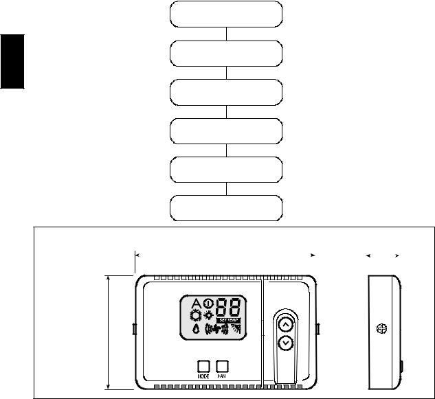
INSTALLATION FLOW CHART
Read manual
Install
Room Controller
Wire Room Controller
and unit network
Configure
Room Controller
Test System
Operate
Room Controller
Dimensions (mm)
|
|
|
|
|
|
|
|
|
|
|
|
|
|
|
4--1/4”(108) |
|
|
3/4”(20) |
||||||||||||||||||||||||||||||||
|
|
|
|
|
|
|
|
|
|
|
|
|
|
|
|
|
|
|
|
|
|
|
|
|
|
|
|
|
|
|
|
|
|
|
|
|
|
|
|
|
|
|
|
|
|
|
|
|
|
|
|
|
|
|
|
|
|
|
|
|
|
|
|
|
|
|
|
|
|
|
|
|
|
|
|
|
|
|
|
|
|
|
|
|
|
|
|
|
|
|
|
|
|
|
|
|
|
|
|
|
|
|
|
|
|
|
|
|
|
|
|
|
|
|
|
|
|
|
|
|
|
|
|
|
|
|
|
|
|
|
|
|
|
|
|
|
|
|
|
|
|
|
|
|
|
|
|
|
|
|
|
|
|
|
|
|
|
|
|
|
|
|
|
|
|
|
|
|
|
|
|
|
|
|
|
|
|
|
|
|
|
|
|
|
|
|
|
|
|
|
|
|
|
|
|
|
|
|
|
|
|
|
|
2--3/14”(70)
SAFETY CONSIDERATIONS
Improper installation, adjustment, alteration, service, maintenance, or use can cause explosion, fire, electrical shock, or other conditions which may cause death, personal injury, or property damage. Consult a qualified installer, service agency, or your distributor or branch for information or assistance. The qualified installer or agency must use factory-authorized kits or accessories when modifying this product. Refer to the individual instructions packaged with the kits or accessories when installing.
Follow all safety codes. Wear safety glasses, protective clothing, and work gloves. Use quenching cloth for brazing operations. Have fire extinguisher available. Read these instructions thoroughly and follow all warnings or cautions included in
literature and attached to the unit. Consult local building codes and National Electrical Code (NEC) for special requirements.
Recognize safety information. This is the safety-alert symbol  When you see this symbol on the unit and in instructions or manuals, be alert to the potential for personal injury. Understand these signal words; DANGER, WARNING, and CAUTION. These words are used with the safety-alert symbol. DANGER identifies the most serious hazards which will result in severe personal injury or death. WARNING signifies hazards which could result in personal injury or death. CAUTION is used to identify unsafe practices which would result in minor personal injury or product and property damage. NOTE is used to highlight suggestions which will result in enhanced installation, reliability, or operation.
2
General information and characteristics
IMPORTANT: Read the entire instruction manual before |
The Room Controller will connect to the receiver board connection |
||||||||
starting the installation. |
on the electronic board inside the unit. |
|
|
||||||
S For trouble-free installation, which should be carried out |
|
|
|
|
|
|
|
|
|
|
|
|
|
|
|
|
|
||
by a qualified installer, follow the installation chart |
|
|
|
|
|
|
|
|
|
sequence. |
|
|
REMOTE |
|
|
|
FCU 1 |
|
|
|
|
|
|
|
|||||
S Follow all current national safety code requirements. In |
|
|
|
|
|
|
|
|
|
particular ensure that a properly sized and connected |
|
|
|
|
|
|
|
|
|
|
|
|
|
|
|
|
|
||
ground wire is in place. |
|
|
|
|
|
|
FCU 2 |
|
|
S After installation, thoroughly test the system operation |
|
|
|
|
|
|
|
||
|
|
|
|
|
|
||||
|
|
|
|
|
|
|
|
||
and explain all system functions to the owner. |
|
|
|
|
|
|
|
|
|
S Leave this manual with the owner for consultation |
|
|
|
|
|
|
|
|
|
|
|
|
|
|
|
FCU 3 |
|
||
during future periodic maintenance. |
|
|
|
|
|
|
|
||
S Dispose of packaging material in accordance with local |
|
|
|
|
|
|
|
|
|
requirements. |
|
|
|
|
|
|
|
|
|
|
|
|
|
|
|
|
|
||
S The manufacturer denies any responsibility and warranty |
|
|
|
|
|
|
FCU 6 |
|
|
shall be void if these installation instructions are not |
|
|
|
|
|
|
|
|
|
observed. |
|
|
|
|
|
|
|
|
|
|
|
|
|
|
|
|
|
||
S Inspect equipment. For damage due to improper |
|
|
|
|
|
|
|
|
|
transportation or handling, file an immediate claim with |
|
|
Fig. 9 – Daisy Chain Wiring (Multidrop) |
||||||
the shipping company. Do not install or use damaged |
POWER |
|
|
||||||
units. |
|
|
|||||||
S In case of any malfunction, turn the unit off, disconnect |
The thermostat will be powered by unregulated 12.5 volts DC |
||||||||
the main power supply and contact a qualified service |
nominal (10V min. to 20V max) |
which is provided by the |
|||||||
electronic board inside the unit. |
|
|
|||||||
engineer. |
|
|
|||||||
|
|
|
|
|
|
|
|
||
WIRING |
The power consumption will be 50mA 12.5 volts DC. |
||||||||
For applications where more than one FCU is to be controlled, the |
|||||||||
The Room Controller will be capable of controlling from 1 to 6 |
|||||||||
FCU closest to the Room Controller will be the only one that |
|||||||||
Fan Coil Units. |
supplies power to the Room Controller. |
||||||||
The total run length of the wire connecting the Room Controller to |
The control should be protected from damage if accidental |
||||||||
the FCUs should be kept to under 500 feet (150 m.). |
miswiring of power, ground and signal. |
||||||||
Only daisy chain wiring will be allowed (See Figure 1).
Choosing the installation site and Installation
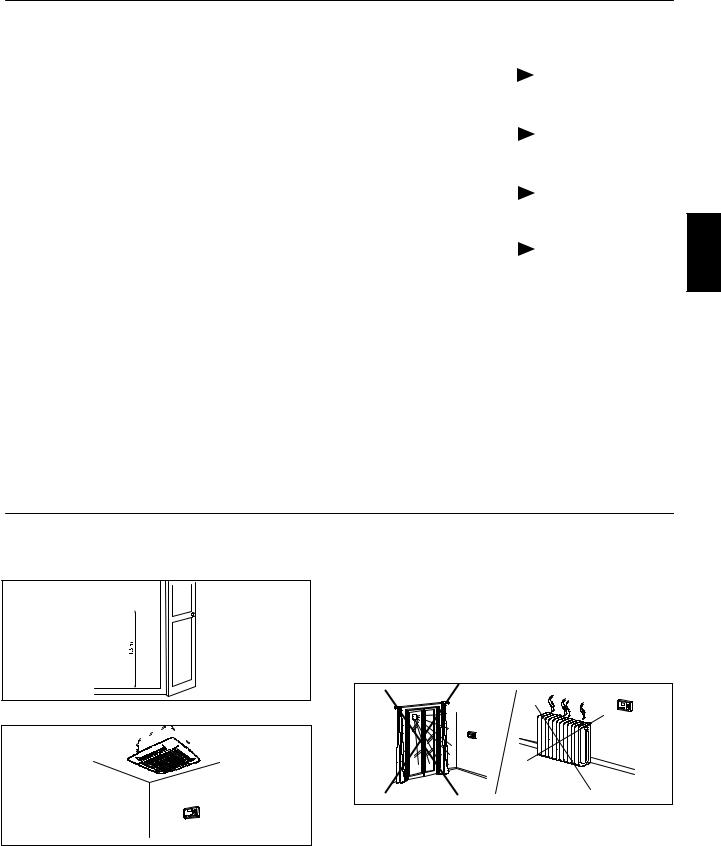
Room Controller Location
The Room Controller can be located anywhere. However, if the installation requires the system in the location to use the air sensor on the Room Controller; then, the controller should be mounted:
S Approximately 5 ft. (1.5 m) from floor.
Fig. 10 – Minimum Clearances
SIn the same area where the unit is located, preferably on an inside partitioning wall.
S On a section of wall without pipes or duct work.
If the air sensor on the Room Controller has been selected, it should NOT be mounted:
SClose to a window, on an outside wall, or next to a door leading to the outside.
SExposed to direct light and heat from a lamp, sun, fireplace, or other temperature-radiating object which may cause a false reading.
SClose to or in direct airflow of a heating or cooling supply.
SIn areas with poor air circulation, such as behind a door or in an alcove.
Maximum of 500 ft. (150 m) of total network wiring.
33MC--URC
3
 Loading...