


8694
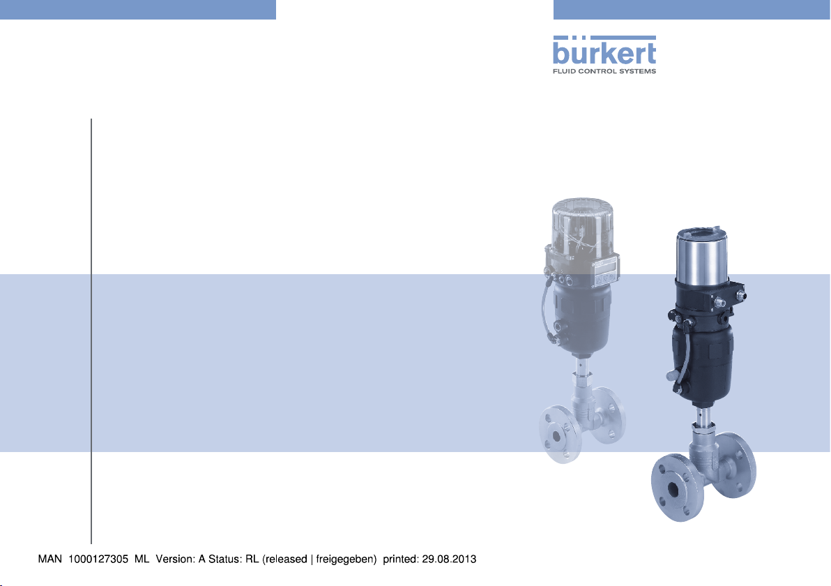
Type 8692 / 8693 / 8694
Exchange of an 8630 positioner with an ELEMENT positioner
Austausch eines 8630-Positioners gegen einen ELEMENT-Positioner
Remplacement d’un positionneur 8630 par un positionneur ELEMENT
Conversion Instructions
Umbauanleitung
Instructions de transformation
We reserve the right to make technical changes without notice.
Technische Änderungen vorbehalten.
Sous réserve de modifications techniques.
© 2009 - 2012 Bürkert Werke GmbH
Operating Instructions 1206/01_EU-ML_00805949 / Original DE
Types 8692, 8693, 8694
Conversion Instructions Positioner
Table of Contents:
1. CONVERSION INSTRUCTIONS ...............................................................4
1.1. Symbols ..............................................................................................4
2. BASIC SAFETY INSTRUCTIONS .............................................................5
3. GENERAL INFORMATION ...........................................................................6
3.1. Contact Addresses .......................................................................... 6
3.2. Warranty ............................................................................................. 6
3.3. Information on the Internet ............................................................. 6
4. INSTALLATION
4.1. Safety instructions ...........................................................................6
4.2. Disassembly of Type 8630 ............................................................7
4.3. Assembling the exchange kit ......................................................... 9
4.4. Install positioner ..............................................................................10
4.5. Pneumatic connection to actuator .............................................11
5. ORDER TABLE FOR EXCHANGE KITS ............................................. 12
..................................................................................................6
english
3
Types 8692, 8693, 8694
Conversion Instructions
1. CONVERSION INSTRUCTIONS
The conversion instructions describe the exchange of a Type 8630
positioner with an ELEMENT positioner (Types 8692, 8693, 8694) on
a Type 27xx control valve. Keep these instructions in a location which is
easily accessible to every user, and make these instructions available
to every new owner of the device.
The operating instructions contain important safety
information!
Failure to observe these instructions may result in hazardous
situations.
• The operating instructions must be read and understood.
For further information on the application, the authorized
use, the technical specifications, start-up and functions as
well as the provisions for packaging, transport, storage and
disposal, please refer to the operating instructions for the
type concerned.
1.1. Symbols
DANGER!
Warns of an immediate danger!
• Failure to observe the warning will result in a fatal or serious
injury.
WARNING!
Warns of a potentially dangerous situation!
• Failure to observe the warning may result in serious injuries or
death.
CAUTION!
Warns of a possible danger!
• Failure to observe this warning may result in a moderate or
minor injury.
NOTE!
Warns of damage to property!
• Failure to observe the warning may result in damage to the
device or the equipment.
Indicates important additional information, tips and
recommendations.
refers to information in these operating instructions or in
other documentation.
→ designates a procedure which you must carry out.
4
english
Types 8692, 8693, 8694
Basic Safety Instructions
2. BASIC
SAFETY INSTRUCTIONS
These safety instructions do not make allowance for any
• contingencies and events which may arise during the installation,
operation and maintenance of the devices.
• local safety regulations – the operator is responsible for observing
these regulations, also with reference to the installation personnel.
DANGER!
Danger – high pressure!
• Before dismounting pneumatic lines and valves, turn off the
pressure and vent the lines.
Risk of electric shock!
• Before reaching into the device or the equipment, switch off the
power supply and secure to prevent reactivation!
• Observe applicable accident prevention and safety regulations
for electrical equipment!
Risk of burns/risk of fire if used continuously through hot
device surface!
• Keep the device away from highly flammable substances and
media and do not touch with bare hands.
The positioners Type 8692, 8693 and 8694 were developed
with due consideration given to the accepted safety rules
and are state-of-the-art. Nevertheless, dangerous situations
may occur.
WARNING!
General Hazardous Situations.
To prevent injury, ensure that:
• the system cannot be activated unintentionally.
• installation and repair work may be carried out by authorized
technicians only and with the appropriate tools.
• after an interruption in the power supply or pneumatic supply,
ensure that the process is restarted in a defined or controlled
manner.
• the device may be operated only when in perfect condition and
in consideration of the operating instructions.
• the general rules of technology apply to application planning
and operation of the device.
NOTE!
Electrostatic sensitive components / modules!
The device contains electronic components, which react sensitively to electrostatic discharge (ESD). Contact with electrostatically charged persons or objects is hazardous to these components. In the worst case scenario, they will be destroyed immediately or will fail after start-up.
• Observe the requirements in accordance with EN 61340-5-1
and 5-2 to minimize or avoid the possibility of damage caused
by sudden electrostatic discharge!
• Also, ensure that you do not touch electronic components when
the power supply voltage is present!
english
5
Types 8692, 8693, 8694
General Information
3. GENERAL INFORMATION
3.1. Contact Addresses
Germany
Bürkert Fluid Control Systems
Sales Center
Chr.-Bürkert-Str. 13-17
D-74653 Ingelfingen
Tel. + 49 (0) 7940 - 10 91 111
Fax + 49 (0) 7940 - 10 91 448
E-mail: info@de.buerkert.com
International
Contact addresses can be found on the final pages of the printed
operating instructions.
And also on the Internet at: www.burkert.com
3.2. Warranty
The warranty is only valid if the positioners are used as intended in
accordance with the specified application conditions.
3.3. Information on the Internet
The operating instructions and data sheets for Types 8692, 8693 and
8694 can be found on the Internet at:
www.burkert.com
4. INSTALLATION
4.1. Safety instructions
DANGER!
Risk of injury from high pressure in the equipment!
• Before dismounting pneumatic lines and valves, turn off the
pressure and vent the lines.
Risk of injury due to electrical shock!
• Before reaching into the device or the equipment, switch off the
power supply and secure to prevent reactivation!
• Observe applicable accident prevention and safety regulations
for electrical equipment!
WARNING!
Risk of injury from improper installation!
• Installation may be carried out by authorized technicians only
and with the appropriate tools!
Risk of injury from unintentional activation of the system and
an uncontrolled restart!
• Secure system from unintentional activation.
• Following assembly, ensure a controlled restart.
6
english
Types 8692, 8693, 8694
Installation
4.2. Disassembly of Type 8630
Procedure:
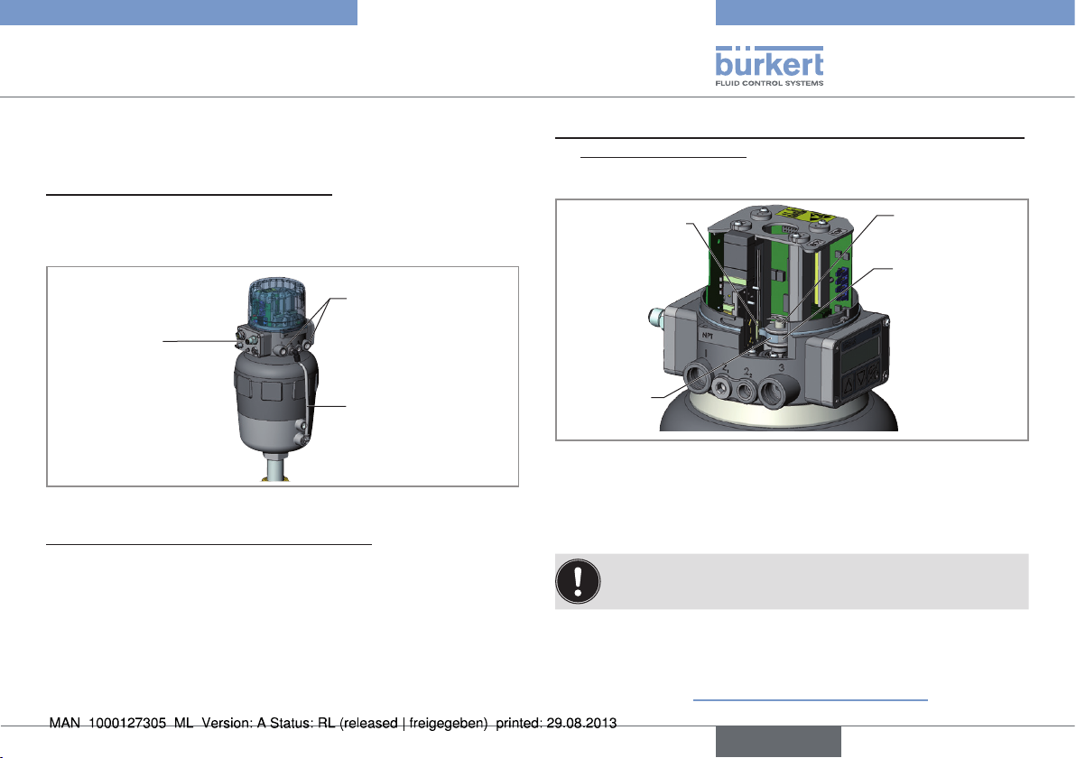
1. Disconnecting pneumatic connection:
→ Remove supply pressure connection and exhaust air connection
(if installed).
→ Loosen pneumatic connection between positioner and actuator.
Supply pressure and
exhaust air connection
Electrical
connection
(multi-pole variant)
Pneumatic
connection
Fig. 1: Disconnecting supply
2. Disconnecting electrical supply connection:
Multi-pole variant:
→ Pull out the round plug.
Cable gland:
→ Loosen the four screws of the cover together with the cable
glands and remove cover.
→ Unscrew the screw terminals and pull out cables.
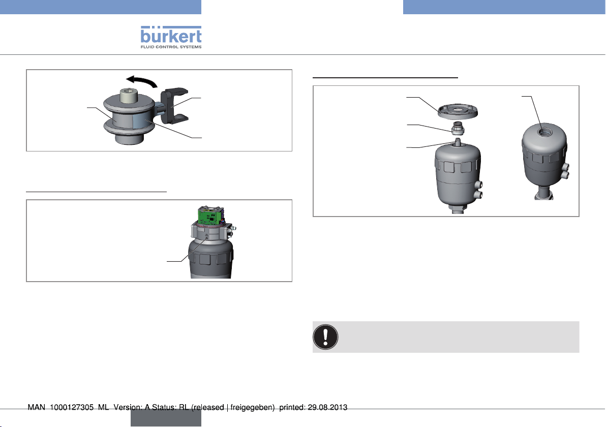
3. Removing the mechanical coupling between position measuring
system and switch cam:
→ Open the transparent hood of the positioner.
Coupling element
position measuring
system
Driving fork
Fig. 2: Coupling position measuring system
The driving fork is clipped onto the coupling element and there are
two options to remove this coupling:
Hexagonal socket
head screw
Switch cam
→ Loosen hexagonal socket head screw and remove switch cam.
The switch cam is secured with screw locking paint. As a
result, increased effort may be required to remove it.
or
→ Remove the driving fork from the coupling element of the
position measuring system by turning a screw driver counterclockwise (see "“Fig. 3: Removing the driving fork”").
english
7
Types 8692, 8693, 8694
Installation
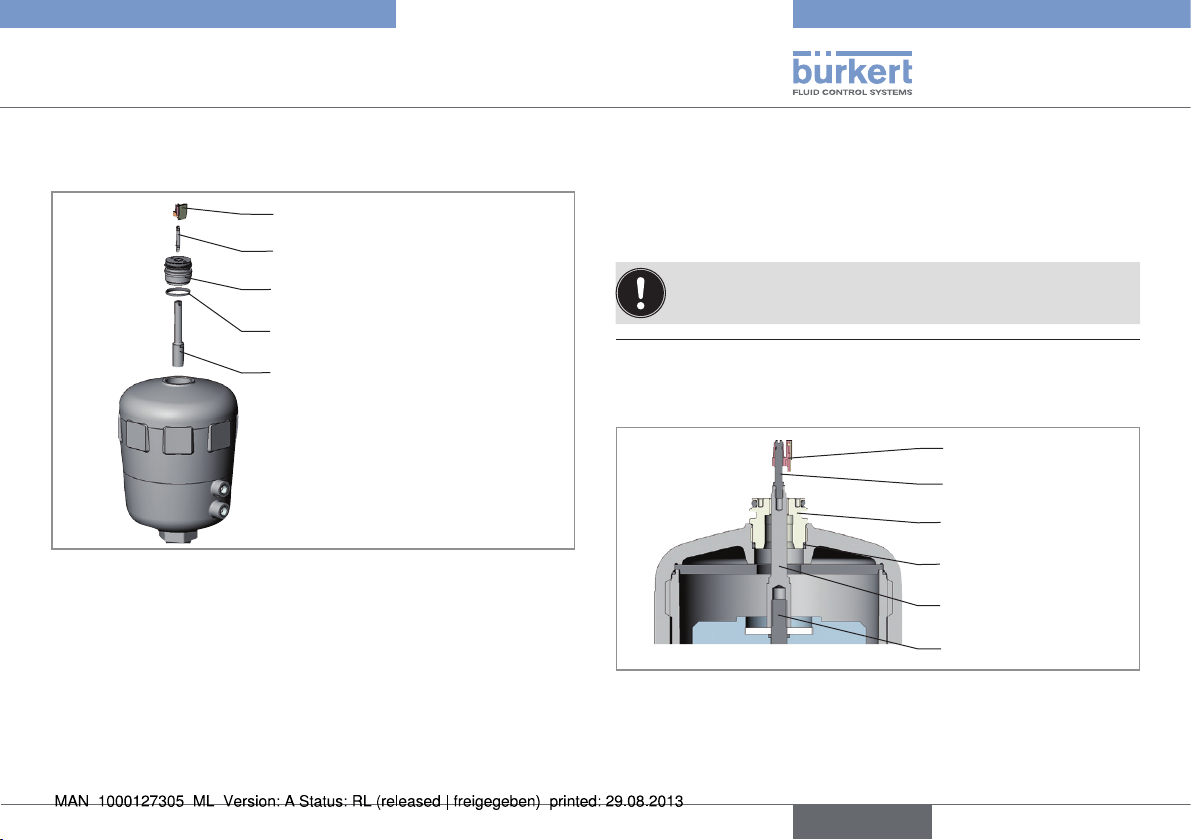
5. Disassembling adaption set 8630
Switch cam
Fig. 3: Removing the driving fork
4. Removing positioner Type 8630:
Fastening screw
Fig. 4: Fastening screw
Coupling element position measuring
system
Driving fork
→ Remove fastening screw (hexagon socket WAF 3) of the
positioner.
→ Remove positioner from actuator.
Spacer ring
Guide piece
Spindle extension
Fig. 5: Disassembling adaption set 8630
O-ring
→ Remove spacer ring
→ Unscrew guide piece
→ Actuator size H (125) and more:
Unscrew spindle extension
→ Remove the O-ring from the cover of the actuator.
The spindle extension is secured with screw locking paint.
As a result, increased effort may be required to remove it.
8
english
Types 8692, 8693, 8694
Installation
4.3. Assembling the exchange kit
Puck holder
Switch spindle
Guide piece
O-ring
Spindle extension
(only with actuator size H (125)
and more)
Fig. 6: Exchange set 869x
→ Actuator size H (125) and more:
Apply some screw locking paint (Loctite 290) in the tapped bore
of the spindle extension and screw to the spindle in the actuator
(torque: 20 ± 3 Nm).
→ Press the O-ring downwards into the cover of the actuator.
→ Screw guide piece into the cover of the actuator using a face
wrench 1) (torque: 8.0 Nm).
→ To secure the switch spindle, apply some locking paint (Loctite
290) to the thread of the switch spindle.
→ Screw switch spindle onto the spindle extension. To do this,
there is a slot on the upper side.
→ Push the puck holder onto the switch spindle until it engages.
The puck holder is not a component of the upgrade kit; it is
enclosed with the control.
1)
Journals : ∅ 3 mm; journal gap: 23.5 mm
Puck holder
Switch spindle
Guide piece
O-ring
Spindle extension
Fig. 7: Exchange set 869x assembled
Spindle (actuator)
english
9
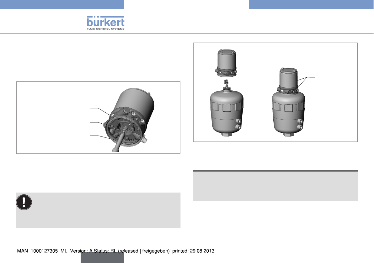
4.4. Install positioner
→ Attach moulded seal from accessories set to positioner.
→ Push the positioner onto the actuator. At the same time, align the
puck holder until it is inserted into the guide rail of the positioner.
Guide rail
Puck holder
Types 8692, 8693, 8694
Installation
Fastening
screws
Moulded seal
Fig. 8: Aligning the puck holder
→ Press the positioner all the way down to the actuator and turn it
into the required position.
Ensure that the pneumatic connections of the positioner
and those of the valve actuator are situated preferably vertically one above the other.
If they are positioned differently, longer hoses may be
required other than those supplied in the accessory kit.
10
english
Fig. 9: Install positioner
NOTE!
Too high torque when screwing in the fastening screw does
not ensure protection class IP65 / IP67!
• The fastening screws may be tightened to a maximum torque of
0.5 Nm only.
→ Attach positioner to the actuator using the two side fastening
screws. In doing so, tighten the screws only hand-tight (max.
torque: 0.5 Nm).
Types 8692, 8693, 8694
Installation
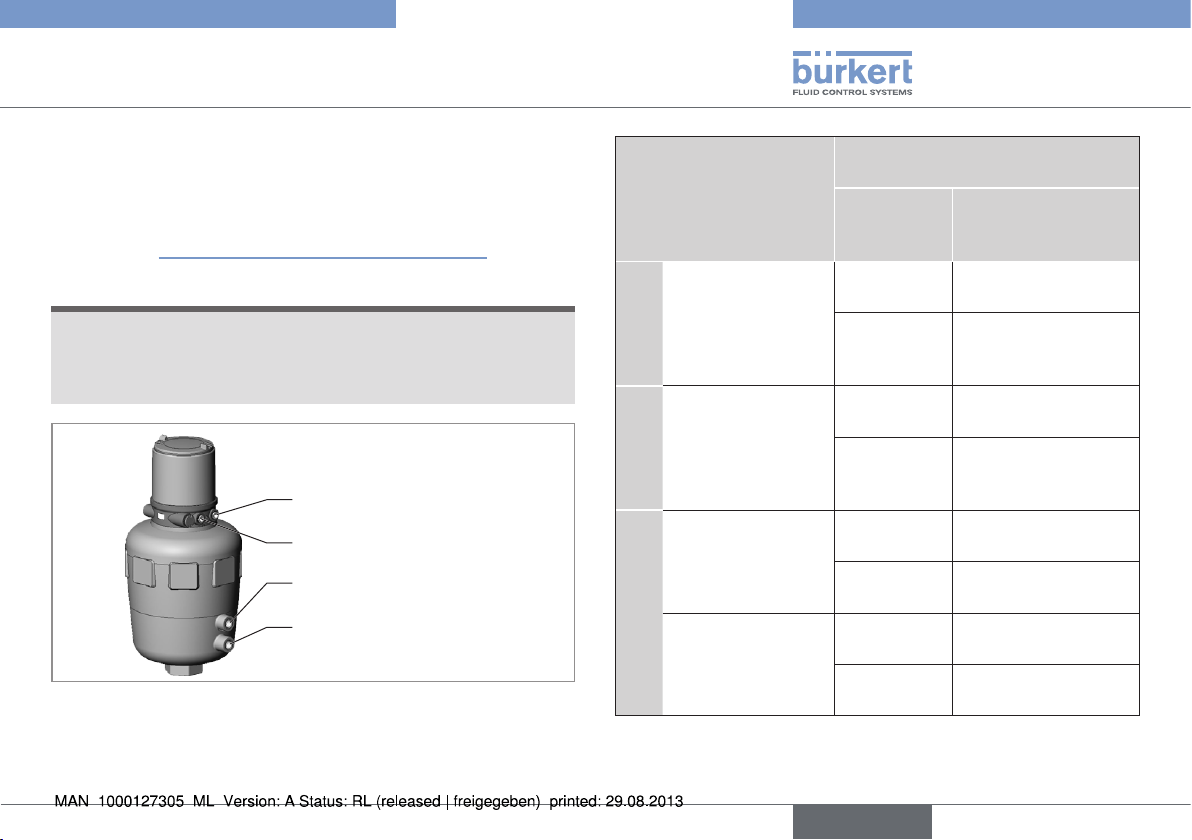
4.5. Pneumatic connection to
actuator
→ Using the hoses supplied in the accessory kit, make the pneu-
matic connection between the positioner and actuator with the
following "“Tab. 1: Pneumatic connection to actuator”".
NOTE!
Damage or malfunction due to ingress of dirt and moisture!
• To comply with protection class IP65 / IP67, connect the control air connection (for CF A und CF B) which is not required to
the free chamber of the actuator or seal with a plug.
Control air connection 2
Control air connection 2
upper chamber
lower chamber
Fig. 10: Pneumatic connection to actuator
1
2
Control function Pneumatic connection
Type 869x to actuator
Control air
Actuator input
connection
Type 869x
Process valve
closed in rest
A
position
(by spring force)
Process valve open
in rest position
B
(by spring force)
Process valve
closed in rest
position
I
Process valve open
in rest position
2
1
2
2
2
1
2
2
2
1
2
2
2
1
2
2
lower chamber of the
actuator
Should be connected
to the upper chamber
of the actuator
upper chamber of the
actuator
Should be connected
to the lower chamber
of the actuator
lower chamber of the
actuator
upper chamber of the
actuator
upper chamber of the
actuator
lower chamber of the
actuator
Tab. 1: Pneumatic connection to actuator
english
11
 Loading...