


HE-800A
ELECTRONIC LOCKSTITCH BUTTON HOLER

Thank you very much for buying a BROTHER sewing machine. Before using your new machine, please read the safety
instructions below and the explanations given in the instruction manual.
With industrial sewing machines, it is normal to carry out work while positioned directly in front of moving parts such as the
needle and thread take-up lever, and consequently there is always a danger of injury that can be caused by these parts.
Follow the instructions from training personnel and instructors regarding safe and correct operation before operating the
machine so that you will know how to use it correctly.
SAFETY INSTRUCTIONS
1. Safety indications and their meanings
This instruction manual and the indications and symbols that are used on the machine itself are provided in order to ensure
safe operation of this machine and to prevent accidents and injury to yourself or other people.
The meanings of these indications and symbols are given below.
Indications
DANGER |
The instructions which follow this term indicate situations where failure to follow the |
instructions will result in death or serious injury. |
The instructions which follow this term indicate situations where failure to follow the CAUTION instructions could cause injury when using the machine or physical damage to equipment
and surroundings.
Symbols
This symbol (  ) indicates something that you should be careful of. The picture inside the triangle
indicates the nature of the caution that must be taken. (For example, the symbol at left means “beware of injury”.)
This symbol ( ) indicates something that you must not do.
This symbol ( ) indicates something that you must do. The picture inside the circle indicates the
nature of the thing that must be done.
(For example, the symbol at left means “you must make the ground connection”.)
HE-800A |
i |

2. Notes on safety
 DANGER
Wait at least 5 minutes after turning off the power switch and disconnecting the power cord from the wall outlet before opening the face plate of the control box. Touching areas where high voltages are present can result in severe injury.
 CAUTION
Environmental requirements
Use the sewing machine in an area which is free from sources of strong electrical noise such as electrical line noise or static electric noise.
Sources of strong electrical noise may cause problems with correct operation.
Any fluctuations in the power supply voltage should be within 10% of the rated voltage for the machine. Voltage fluctuations which are greater than this may cause problems with correct operation.
The power supply capacity should be greater than the requirements for the sewing machine’s power consumption.
Insufficient power supply capacity may cause problems with correct operation.
The ambient temperature should be within the range of 5 C to 35 C during use.
Temperatures which are lower or higher than this may cause problems with correct operation.
The relative humidity should be within the range of 45% to 85% during use, and no dew formation should occur in any devices.
Excessively dry or humid environments and dew formation may cause problems with correct operation.
In the event of an electrical storm, turn off the power and disconnect the power cord from the wall outlet. Lightning may cause problems with correct operation.
Installation
Machine installation should only be carried out by a qualified technician.
Contact your Brother dealer or a qualified electrician for any electrical work that may need to be done.
The sewing machine weighs approximately 56 kg. The installation should be carried out by two or more people.
Do not connect the power cord until installation is complete, otherwise the machine may operate if the treadle is depressed by mistake, which could result in injury.
Use both hands to hold the machine head when tilting it back or returning it to its original position. If only one hand is used, the weight of the machine head may cause your hand to slip, and your hand may get caught.
Be sure to connect the ground. If the ground connection is not secure, you run a high risk of receiving a serious electric shock, and problems with correct operation may also occur.
All cords should be secured at least 25 mm away from any moving parts. Furthermore, do not excessively bend the cords or secure them too firmly with staples, otherwise there is the danger that fire or electric shocks could occur.
Install the belt covers to the machine head and motor.
If using a work table which has casters, the casters should be secured in such a way so that they cannot move.
Be sure to wear protective goggles and gloves when handling the lubricating oil and grease, so that they do not get into your eyes or onto your skin, otherwise inflammation can result.
Furthermore, do not drink the oil or eat the grease under any circumstances, as they can cause vomiting and diarrhoea.
Keep the oil out of the reach of children.
ii |
HE-800A |

CAUTION |
||
Sewing |
|
|
This sewing machine should only be used by opera- |
If using a work table which has casters, the casters |
|
tors who have received the necessary training in safe |
should be secured in such a way so that they cannot |
|
use beforehand. |
move. |
|
The sewing machine should not be used for any |
Attach all safety devices before using the sewing |
|
applications other than sewing. |
machine. If the machine is used without these |
|
Be sure to wear protective goggles when using the |
devices attached, injury may result. |
|
Do not touch any of the moving parts or press any |
||
machine. |
||
If goggles are not worn, there is the danger that if a |
objects against the machine while sewing, as this |
|
needle breaks, parts of the broken needle may enter |
may result in personal injury or damage to the |
|
your eyes and injury may result. |
machine. |
|
Turn off the power switch at the following times, |
Do not touch the motor cover during operation and for |
|
otherwise the machine may operate if the treadle is |
one hour after operation has finished, otherwise |
|
depressed by mistake, which could result in injury. |
burns may result. |
|
When threading the needle |
If an error occurs in machine operation, or if abnormal |
|
When replacing the needle and bobbin |
noises or smells are noticed, immediately turn off the |
|
When not using the machine and when leaving the |
power switch. Then contact your nearest Brother |
|
machine unattended |
dealer or a qualified technician. |
|
|
If the machine develops a problem, contact your |
|
|
nearest Brother dealer or a qualified technician. |
|
|
||
Cleaning |
||
Turn off the power switch before carrying out |
Be sure to wear protective goggles and gloves when |
|
cleaning, otherwise the machine may operate if the |
handling the lubricating oil and grease, so that they |
|
treadle is depressed by mistake, which could result in |
do not get into your eyes or onto your skin, otherwise |
|
injury. |
inflammation can result. |
|
|
Furthermore, do not drink the oil or eat the grease un- |
|
|
der any circumstances, as they can cause vomiting |
|
|
and diarrhoea. |
|
|
Keep the oil out of the reach of children. |
|
|
||
Maintenance and inspection |
||
Maintenance and inspection of the sewing machine |
If the power switch needs to be left on when carrying |
|
should only be carried out by a qualified technician. |
out some adjustment, be extremely careful to observe |
|
Ask your Brother dealer or a qualified electrician to |
all safety precautions. |
|
Use both hands to hold the machine head when tilting |
||
carry out any maintenance and inspection of the |
||
electrical system. |
it back or returning it to its original position. If only |
|
Turn off the power switch and disconnect the power |
one hand is used, the weight of the machine head |
|
may cause your hand to slip, and your hand may get |
||
cord from the wall outlet at the following times, |
||
caught. |
||
otherwise the machine may operate if the treadle is |
||
Use only the proper replacement parts as specified |
||
depressed by mistake, which could result in injury. |
||
When carrying out inspection, adjustment and main- |
by Brother. |
|
tenance |
If any safety devices have been removed, be abso- |
|
When replacing consumable parts such as the ro- |
lutely sure to re-install them to their original positions |
|
tary hook |
and check that they operate correctly before using |
|
Turn off the power switch before inserting or |
the machine. |
|
Any problems in machine operation which result from |
||
removing the plug, otherwise damage to the control |
||
box could result. |
unauthorized modifications to the machine will not be |
|
|
covered by the warranty. |
|
|
|
|
HE-800A |
iii |
|

3. Warning labels
The following warning labels appear on the sewing machine.
Please follow the instructions on the labels at all times when using the machine. If the labels have been removed or are difficult to read, please contact your nearest Brother dealer.
1
2a
2b
3 
4
5
NOTE:
Either the 2a or the 2b label is displayed on the sewing machine.
*Safety devices
Eye guard, Finger guard, Thread take-up cover, Belt cover, Belt cover plate, etc.
Be sure to connect the ground. If the ground connection is not secure, you run a high risk of receiving a serious electric shock, and problems with correct operation may also occur.
Do not touch any of the cutter or press any objects against the machine while sewing, as this may result in personal injury or damage to the machine.
Do not touch any of the fan or press any objects against the machine, as this may result in personal injury or damage to the machine.
6 
7
High temperature warning display
Direction of operation
iv |
HE-800A |

Thread take-up cover
Belt cover
Eye guard
Belt cover plate
Finger guard
4404M
HE-800A |
v |
CONTENTS
1. NAME OF EACH PART........................ |
1 |
2. SPECIFICATIONS ................................ |
2 |
2-1. Specifications ................................................. |
2 |
2-2. Standard sewing pattern list ........................... |
3 |
3. OPTIONAL PARTS............................... |
4 |
3-1. Special needle plate ....................................... |
4 |
3-2. Leg parts......................................................... |
4 |
3-3. Standing operation pedal................................ |
5 |
3-4. Ruler ............................................................... |
5 |
3-5. Tape guard ..................................................... |
6 |
4.INSTALLATION...................................... |
7 |
4-1. Table processing diagram .............................. |
7 |
4-2. Installing the motor ......................................... |
8 |
4-3. Installing the flange nut................................... |
9 |
4-4. Installing the control box................................. |
9 |
4-5. Installing the power switch.............................. |
10 |
4-6. Installing the bed base.................................... |
10 |
4-7. Installing the machine head............................ |
11 |
4-8. Installing the head rest ................................... |
11 |
4-9. Installing the operation panel ......................... |
12 |
4-10. Routing the connector cord and |
|
installing the oil stopper plate ....................... |
12 |
4-11. Connecting the cords.................................... |
13 |
4-11-1. Connecting the ground wire.............. |
13 |
4-11-2. Connecting the machine |
|
head harness .................................... |
13 |
4-11-3. Connecting the motor harness.......... |
14 |
4-11-4. Connecting the power cord............... |
15 |
4-11-5. Connecting the standing operation |
|
pedal harness (option) ...................... |
16 |
4-11-6. Installing the transformer .................. |
17 |
4-12. Installing the V-belt....................................... |
19 |
4-13. Installing the belt cover plate........................ |
20 |
4-14. Installing the treadle connecting rod............. |
21 |
4-14-1. Changing the treadle unit |
|
installation position |
|
(horizontal positioning only) .............. |
22 |
4-15. Installing the spool stand.............................. |
23 |
4-16. Installing the eye guard ................................ |
23 |
4-17. Lubrication .................................................... |
24 |
4-17-1. Lubricating the bed base................... |
24 |
4-17-2. Lubricating the arm ........................... |
25 |
4-17-3. Lubricating the rotary hook ............... |
25 |
4-18. Installing the belt cover................................. |
26 |
4-19. Installing the auxiliary table .......................... |
26 |
5. OPERATION......................................... |
27 |
5-1. Name and function of each operation panel item..27 |
|
5-2. Home position detection (preparation)............ |
29 |
5-3. Operating the treadle ...................................... |
30 |
5-3-1. Operating the standing operation |
|
pedal (option) ...................................... |
31 |
5-4. Program setting method.................................. |
32 |
5-4-1. Program setting examples................... |
33 |
5-4-2. Checking the length of knife ................ |
35 |
5-5. Parameter table .............................................. |
36 |
5-5-1. Available sewing area.......................... |
45 |
5-5-2. Setting the knife length........................ |
46 |
5-5-3. Buttonhole sewing size........................ |
46 |
5-5-4. Main restrictions when setting |
|
parameters .......................................... |
46 |
5-6. Rear tack vector shape programs................... |
48 |
5-7. Underlay programs ......................................... |
49 |
5-8. Cutter operation .............................................. |
50 |
5-9. Cycle program................................................. |
51 |
5-10. Production counter........................................ |
52 |
5-11. Bobbin thread counter................................... |
53 |
5-12. Using the program memos............................ |
53 |
5-13. Adding patterns created using the |
|
programming software for electronic |
|
pattern sewer................................................. |
54 |
6. CHECKING THE SEWING PATTERN .55 |
|
6-1. Test feed mode ............................................... |
55 |
6-2. Manual mode .................................................. |
56 |
7. CORRECT USE.................................... |
57 |
7-1. Installing the needle........................................ |
57 |
7-2. Threading the upper thread ............................ |
58 |
7-3. Winding the lower thread ................................ |
59 |
7-4. Threading the bobbin case ............................. |
60 |
7-5. Thread tension ................................................ |
61 |
7-5-1. Lower thread tension........................... |
61 |
7-5-2. Upper thread tension........................... |
62 |
7-5-3. Thread take-up spring height .............. |
63 |
7-5-4. Thread take-up spring tension............. |
63 |
7-5-5. Adjusting arm thread guide ................. |
63 |
8. SEWING ............................................... |
64 |
8-1. Sewing ............................................................ |
64 |
8-2. If the stop switch is pressed during sewing .... |
65 |
8-3. If the thread breaks during sewing.................. |
66 |
8-4. Thread breakage before sewing is finished.... |
67 |
8-5. When resuming sewing in test feed mode |
|
or manual mode .............................................. |
68 |
HE-800A
9.CLEANING AND MAINTENANCE ......... |
69 |
9-1. Cleaning ......................................................... |
69 |
9-2. Draining the oil................................................ |
70 |
9-3. Cleaning the control box air inlet port............. |
70 |
9-4. Cleaning the eye guard .................................. |
70 |
9-5. Checking the needle....................................... |
71 |
9-6. Cleaning the length feed plate........................ |
71 |
10. STANDARD ADJUSTMENTS ............ |
72 |
10-1. Adjusting the needle bar height.................... |
72 |
10-2. Adjusting the needle and hook timing .......... |
73 |
10-3. Adjusting the clearance between needle |
|
and hook point .............................................. |
73 |
10-4. Adjusting the inner rotary hook and |
|
rotary hook holder overlap............................ |
74 |
10-5. Adjusting the work clamp pressure .............. |
74 |
10-6. Adjusting the cutter installation..................... |
74 |
10-7. Adjusting the upper thread trimming ............ |
75 |
10-7-1. Adjusting the installation height of |
|
the upper thread scissors.................. |
75 |
10-7-2. Adjusting the upper thread scissors |
|
opening timing................................... |
76 |
10-8. Adjusting the lower thread clamp timing....... |
77 |
10-9. Adjusting the bobbin presser........................ |
77 |
10-10. Adjusting the needle up stop position......... |
77 |
11. CHANGING FUNCTIONS USING |
|
THE MEMORY SWITCHES................ |
78 |
11-1. Memory switch table..................................... |
79 |
12. PROGRAM INITIALIZATION.............. |
80 |
12-1. Initializing all programs................................. |
80 |
12-2. Initializing a single program.......................... |
80 |
13. CHANGING FUNCTIONS USING |
|
THE DIP SWITCHES .......................... |
81 |
13-1. Panel DIP switches....................................... |
81 |
13-2. Circuit board DIP switches ........................... |
83 |
14. ERROR CODE TABLE....................... |
85 |
15. GAUGE PARTS LIST ......................... |
89 |
16. TROUBLESHOOTING........................ |
92 |
16-1. Upper thread breakage................................. |
92 |
16-2. Skipped stitches ........................................... |
93 |
16-3. Uneven seams (1) …… |
|
At the sewing start..................................... |
94 |
16-4. Uneven seams (2) …… |
|
Lower thread is lifted up at |
|
the sewing start ......................................... |
95 |
16-5. Uneven seams (3) …… |
|
Seam lifts up at the sewing start................ |
96 |
16-6. Uneven seams (4) …… |
|
Uneven sewing pitch at the sewing start .... |
96 |
16-7. Uneven seams (5) …… |
|
Poor rounding of seam ................................. |
96 |
16-8. Uneven seams (6) …… |
|
Around rear tack or front tack.................... |
96 |
16-9. Uneven seams (7) …… |
|
Loose thread end at end backtack ............ |
97 |
16-10. Uneven seams (8) …… |
|
Thread sticking out at end backtack ........ |
97 |
16-11. Uneven seams (9) …… |
|
Sticking in needle plate............................ |
97 |
16-12. Uneven seams (10) …… |
|
All stitches................................................ |
98 |
16-13. Upper thread run out................................... |
99 |
16-14. Unraveling of thread trimmed by upper |
|
thread trimmer assembly........................... |
101 |
16-15. Upper thread mis-trimming ....................... |
102 |
16-16. Needle strikes upper thread trimmer ........ |
102 |
16-17. Needle breakage....................................... |
103 |
16-18. Imperfect cutter function |
|
(imperfect material cutting)........................ |
104 |
16-19. Cutter does not return............................... |
105 |
16-20. Cutter and upper thread scissors touch.... |
105 |
16-21. Seam is cut ............................................... |
105 |
16-22. Upper thread mis-winding......................... |
106 |
16-23. Work clamp is not raised (1) Pulse motor |
|
stepping sound cannot be heard............... |
106 |
16-24. Work clamp is not raised (2) Pulse motor |
|
stepping sound can be heard.................... |
107 |
16-25. Lower thread is not trimmed |
|
(pulls when material is removed)............... |
108 |
16-26. Feed mechanism does not operate or |
|
motor is out of step.................................... |
108 |
16-27. Needle does not zigzag or noise occurs |
|
when needle zigzags................................. |
109 |
16-28. Sewing machine stops during sewing....... |
109 |
16-29. Upper shaft does not rotate as far as |
|
the needle up stop position ....................... |
109 |
HE-800A

1. NAME OF EACH PART
. NAME OF EACH PART
4110M
(1) Power switch |
(2) Control box |
(3) |
Operation panel |
||
(4) Treadle |
(5) AC servo motor |
(6) |
Stop switch |
||
(7) Spool stand |
(8) Pulley |
(9) |
Tension release lever |
||
Safety devices |
|
|
|
|
|
(10) |
Eye guard |
(11) Thread take-up cover |
(12) |
Belt cover |
|
(13) |
Belt cover plate |
(14) Finger guard |
(15) |
Finger protector |
|
(16) |
Belt retainer |
|
|
|
|
1 |
HE-800A |

|
2. SPECIFICATIONS |
|
|
. SPECIFICATIONS
- . Specifications
|
Main use |
|
|
|
Buttonhole size |
||
|
Buttonholes for clothing such as dress |
|
A |
|
|
||
|
shirts, blouses, work clothes and women's |
|
|
|
|
||
-2 |
clothes |
|
|
|
|
|
|
|
|
|
|
|
|
|
|
|
|
|
|
B |
C |
|
D |
|
Buttonholes for knitted garments such as |
||||||
|
|
|
|
|
|||
|
knitted underwear, |
sweaters, cardigans |
|
|
|
|
|
|
and jerseys |
|
|
|
|
|
A: Max.6 mm |
|
|
|
|
|
|
|
|
-3 |
|
|
|
|
|
|
B: Max. zigzag stitch length 39 mm |
|
|
|
|
|
|
|
C: Length of knife 4 – 32 mm |
|
|
|
|
|
|
|
D: Max. buttonhole length 40 mm |
|
|
|
|
|
|
|
2193Q |
|
|
|
|
|
|
|
|
|
|
|
|
|
|
||
Max. sewing speed |
|
|
|
4,000 sti/min |
|||
|
Zigzag mechanism |
|
|
|
Pulse motor driven mechanism |
||
|
Feed mechanism |
|
|
|
Pulse motor driven mechanism |
||
Work clamp lifter mechanism |
|
|
Pulse motor driven mechanism |
||||
Height of work clamp |
|
|
|
13 mm max. (adjustable) |
|||
|
Knife mechanism |
|
|
|
Double position solenoid |
||
Lower thread holding device |
|
|
Standard equipment |
||||
|
Bobbin presser |
|
|
|
Standard equipment |
||
Standard sewing pattern |
|
|
|
|
21 |
||
|
Memory pattern |
|
|
|
|
90 |
|
Max. number of stitch |
|
700 stitches / program |
(Overall cycle program stitch no. 3,000 stitches) |
||||
|
Needle |
|
-2 |
|
|
-3 |
|
|
|
Schmetz 134 Nm90 |
|
Schmetz 134 Nm75 |
|||
|
|
|
|
||||
Data storage method |
|
P-ROM (Custom made pattern can be added by the programming software for |
|||||
|
|
|
electronic pattern sewer) |
||||
|
|
|
|
|
|||
|
Power supply |
|
|
Single phase 110 V, 220 V, 230 V |
|||
|
|
|
Three phase 220 V, 380 V, 400 V 600 VA |
||||
|
|
|
|
||||
HE-800A |
2 |

2. SPECIFICATIONS
- . Standard sewing pattern list
[1] Rectangle |
[2] Radial |
[3] Round |
[4] Straight bar tack |
 Rear tack
 Front tack
[0] Free (Combinations of rear tack shapes and the front tack shapes - 17 patterns)
Radial-rectangle |
Round-rectangle |
Eyelet-rectangle |
Rectangle-radial |
Round-radial |
Eyelet-radial |
|
|
|
|
|
|
Rectangle-round |
Radial-round |
Eyelet-round |
Rectangle-taper tack |
Radial-taper tack |
Round-taper tack |
|
|
|
|
|
|
Eyelet-taper tack |
Rectangle-tack |
Radial-tack |
Round-tack |
Eyelet-tack |
|
|
|
|
|
|
|
*[0] to [4] indicate the setting range for parameter No. 1. (Refer to "5-5. Parameter table".)
*In addition to the above shapes, you can create and use up to 9 additional custom made patterns using the programming software for electronic pattern sewer.
3 |
HE-800A |

|
|
|
|
|
|
3. OPTIONAL PARTS |
||
|
|
|
|
|
|
|
|
|
|
|
|
|
|
|
|
|
|
|
. OPTIONAL PARTS |
|
|
|
|
|
|
|
|
|
|
This needle plate uses the elasticity of rubber to |
|||||
|
|
|
||||||
|
|
|
prevent the cutter from getting stuck and not returning. |
|||||
|
|
|
It also helps to keep the cutter blade sharp. |
|||||
|
|
|
* The standard cutter can be used. |
|||||
|
|
|
|
|
|
|
|
|
|
|
|
|
Parts name |
|
Parts code |
|
|
|
|
|
|
Needle plate set 1.2RB |
|
S51361-001 |
|
|
|
|
|
-2 |
Needle plate set 1.4RB |
|
S51362-001 |
|
|
|
|
|
|
Needle plate set 1.6RB |
|
S51363-001 |
|
|
|
|
|
|
Needle plate set 1.2RB-3 |
|
S51364-001 |
|
|
|
|
|
-3 |
Needle plate set 1.4RB-3 |
|
S51365-001 |
|
|
|
2037Q |
|
|
Needle plate set 1.6RB-3 |
|
S51366-001 |
|
|
|
|
|
|
|
|
|
|
|
|
|
|
|
|
|
|
|
|
|
|
|
|
|
|
|
|
|
|
Parts name |
|
|
|
|
|
Parts code |
|
|
|
Spacer set |
|
183504-109 |
|
|||
|
2038Q |
|
|
|
|
|
|
|
|
|
|
|
|
|
|||
|
2039Q |
Caster set |
|
183501-001 |
|
|||
|
- . Special needle plate |
|
|
|
|
|
|
|
|
- . Leg parts |
|
|
|
|
|
|
|
|
|
|
|
|
|
|
|
|
HE-800A |
4 |

3. OPTIONAL PARTS
- . Standing operation pedal
|
|
Parts name |
Parts code |
||
|
|
|
|
|
<Except for Europe> |
|
|
|
Three pedals |
J80380-040 |
|
|
|
|
<For Europe only> |
||
|
|
|
|
|
|
|
|
|
|
|
J80380-0E0 |
|
|
2041Q |
|
|
|
|
|
|
|
|
|
|
|
|
Harness for standing operation pedal |
S47750-000 |
|
|
|
3854Q |
|
|
|
|
|
|
|
|
|
- . Ruler |
|
|
|
|
|
|
|
|
|
|
|
|
|
Parts name |
Parts code |
||
Horizontal |
|
|
|
Ruler assy 800E |
S50350-001 |
ruler |
|
|
|
||
|
|
|
|
|
|
|
|
2043Q |
|
|
|
|
|
|
|
|
|
Vertical |
|
|
|
Ruler assy |
S50477-001 |
ruler |
|
|
|
||
|
|
|
|
|
|
|
|
2044Q |
|
|
|
|
|
|
|
|
|
5 |
HE-800A |

|
3. OPTIONAL PARTS |
|
|
- . Tape guard
Tape guard winder assy
S50346-001
Tape winder assy 143767-102
Tape guard assy
S51896-001
2042Q
HE-800A |
6 |

4. INSTALLATION
. INSTALLATION
 CAUTION
Machine installation should only be carried out by |
All cords should be secured at least 25 mm away |
|
a qualified technician. |
from any moving parts. Furthermore, do not |
|
Contact your Brother dealer or a qualified |
excessively bend the cords or secure them too |
|
firmly with staples, otherwise there is the danger |
||
electrician for any electrical work that may need |
||
that fire or electric shocks could occur. |
||
to be done. |
||
Be sure to connect the ground. If the ground |
||
The sewing machine weighs approximately 56 kg. |
||
connection is not secure, you run a high risk of |
||
The installation should be carried out by two or |
||
receiving a serious electric shock, and problems |
||
more people.. |
||
with correct operation may also occur. |
||
Do not connect the power cord until installation is |
||
Install the belt covers to the machine head and |
||
complete, otherwise the machine may operate if |
||
motor. |
||
the treadle is depressed by mistake, which could |
||
|
||
result in injury. |
|
|
Use both hands to hold the machine head when |
|
|
tilting it back or returning it to its original position. |
|
|
If only one hand is used, the weight of the |
|
|
machine head may cause your hand to slip, and |
|
|
your hand may get caught. |
|
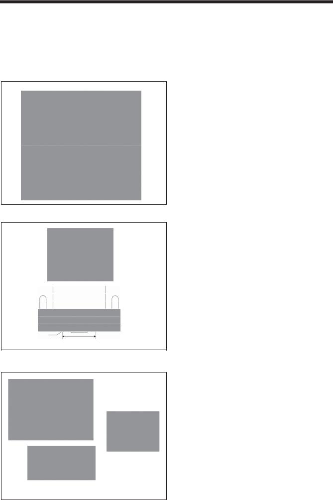
- . Table processing diagram
The thickness of the table should be at least 40 mm, and it should be strong enough to bear the weight and vibration of the sewing machine.
The method for processing the table will vary depending on whether the positioning method is vertical or horizontal. Make the holes in the correct places while referring to the table processing diagram which matches the positioning method.
[Vertical positioning]
4091M
7 |
HE-800A |

|
4. INSTALLATION |
|
|
[Horizontal positioning]
4095M
- . Installing the motor
Install the motor (1) with the three bolts (2), flat
washers (3), spring washers (4) and nuts (5).
3856Q
HE-800A |
8 |

4. INSTALLATION
- . Installing the flange nut
Install the four flange nuts (1) to the underside of the work table.
Note:
When the machine head is positioned horizontally, some flange nut installation locations may be inaccessible after the control box has been installed.
3857Q
- . Installing the control box
Note: When opening the cover, hold it securely so that it does not fall down.
3858Q
1.Remove the 12 screws (1), and then open the covers (main P.C. board mounting plate (2) and sub P.C. board mounting plate (3)).
2.Install the control box with the bolts (4), cushions (5), cushion collars (6), rubber collars (7), flat washers (8) and nuts
(9) as shown in the illustration. At this time, leave a gap of approximately 2 mm between the work table and the top of the box.
3.Close the covers (main P.C. board mounting plate (2) and sub P.C. mounting plate (3)), and provisionally tighten them with the screws (1). (They will be opened again when the cords are connected.)
9 |
HE-800A |

|
4. INSTALLATION |
|
|
- . Installing the power switch
1. Install the power switch (1) with the two screws (2). 2. Secure the power switch (1) cord and the motor (4)
cord with the six staples (3).
3859Q
- . Installing the bed base
4069M
1.Place the bed base (1) on top of the work table, and insert the four collars (2).
2.Provisionally tighten the four flange nuts (4) onto the four bolts (3), and then position the bed base (1).
3.Install the bed base (1) with the three flat washers (5) and wood screws (6), and then install the two rubber caps (7).
4.Remove the four bolts (3).
5.Set the magnet (8) in the position shown in the illustration.
HE-800A |
10 |

4. INSTALLATION
- . Installing the machine head
3861Q
3862Q
1.Place the two bed hinges (1) so that they are level as shown in the illustration at left, and then place
the machine head gently on top of the bed base (3) so that the cables (2) do not get clamped.
Note:
The bed base (3) is made from plastic, so be careful not to hit it with the machine head when placing the machine head on top of it.
2.Install the machine head with the four spring washers (4) and four bolts (5).
Note:
Make sure that the felt support (6) do not touch the bed base (3).
- . Installing the head rest
2778Q
Tap the head rest (1) into the table hole.
Note:
Tap the head rest securely into the table hole.
If the head rest is not pushed in as far as it will go, the machine head will not be sufficiently stable when it is tilted back.
11 |
HE-800A |

|
4. INSTALLATION |
|
|
- . Installing the operation panel
3863Q
Top of work table
Table
Bottom of work table
Table
3864Q
The operation panel can be installed to either the top or bottom of the work table.
1.Install the rear frame (1) to the work table (top or bottom) with the four wood screws (2).
2.Install the front frame assembly (3) to the rear frame
(1)with the four screws (4).
* The vertical orientation of the front frame assembly
(3)is the same whether it is installed to the top or
the bottom of the work table.
*Pull the harnesses such as the ground harness out of the way so that the operation panel side cover
(5) can be opened and closed.
3.Insert the connector cord (6) into the control box through the hole at the side of the box.
- . Routing the connector cord and installing the oil stopper plate
3865Q
1. Gently tilt back the machine head.
2. Pass the cords (1) through the hole in the work table.
3. Install the oil stopper plate (2).
4. Move the connector cord (1) so that it will not be clamped by the machine head and the bed base (3), and then return the machine head to its original position.
3866Q
HE-800A |
12 |
4. INSTALLATION
- . Connecting the cords
The harness is connected in the same way regardless of whether the machine head is positioned horizontally or
vertically.
- - . Connecting the ground wire
 CAUTION
Be sure to connect the ground. If the ground connection is not secure, you run a high risk of receiving a serious electric shock, and problems with correct operation may also occur.
Grounding mark
Grounding mark
3867Q
1.Remove the 12 screws (1), and then open the covers (main P.C. board mounting plate (2) and sub P.C. board mounting plate (3)).
Note: When opening the cover, hold it securely so that it does not fall down.
2.Insert the panel harness (4) into the control box.
3.Connect the ground wire (5) which is protruding out from the hole at the side of the control box to the leg (6).
4.Connect the ground wire (7) coming from the machine head to the grounding point (8) inside the control box.
5.Connect the ground wire in the panel harness to the ground point (9) inside the control box.
* Grounding marks are displayed on the machine head and inside the control box.
Note: If the shape of the grounding screw in the leg (6) requires a different ground wire to be connected, replace the ground wire with the accessory ground wire.
If the ground wires are not connected, incorrect operation may result.
If the grounding point has been painted over, remove the paint coating before connecting the ground wire.
- - . Connecting the machine head harness
1. Insert the machine head harness (1) into the control box.
2. Gently tilt back the machine head.
3. Pull the harness (1) through the cord clamp (2) at the top of the control box.
* This cord clamp is not used when the machine head is positioned horizontally.
3868Q
13 |
HE-800A |

|
4. INSTALLATION |
|
|
- - . Connecting the motor harness
3869Q
1.Pass the motor harness (1) through the cord bush
(2).
2.Connect the connectors (3).
3.Secure the motor harness (1) with staples.
3870Q
3871Q
4.Securely insert each of the connectors (4) – (8) as indicated below.
|
Harness |
Mark |
Sub P.C. board |
|
indication |
||
|
|
|
|
(4) |
Feed motor |
S2 |
P2 FDPM |
|
<5-pin>(White) |
|
|
(5) |
Presser foot motor |
S5 |
P5 FTPM |
|
<5-pin> (Blue) |
|
|
(6) |
Cutter solenoid |
S8 |
P8 CUTTER |
|
<6-pin> |
|
|
(7) |
Fan <3-pin> |
- |
P10 FAN1 |
(8) |
Cutter home position |
S7 |
P7 OPSEN2 |
|
sensor <12-pin> |
|
|
5.Securely insert the connectors (9) and (10) as indicated below.
Note:
Take note of how these two harnesses are routed through the control box so as not to confuse them with any of the other harnesses.
|
Harness |
Mark |
Main P.C. board |
|
indication |
||
|
|
|
|
(9) |
Zigzag motor |
M16 |
P16 NPM |
|
<6-pin> |
|
|
(10) |
Tension release |
M19 |
P19 OPSOL |
|
solenoid <6-pin> |
|
|
HE-800A |
14 |

4. INSTALLATION
3872Q
6.Securely insert each of the connectors (11) – (13) as indicated below.
|
Harness |
Mark |
Main P.C. board |
|
|
|
indication |
(11) |
Synchronizer <5-pin> |
M3 |
P3 SYNC |
(12) |
Home position sensor |
M11 |
P11 ORG |
|
<12-pin> |
|
|
(13) |
Stop switch <11-pin> |
M10 |
P10 HEAD |
7.Secure the harnesses inside the control box using cord clamps as shown in the illustration.
Note:
•Make sure that the harnesses do not come into contact with P.C. board components or with the main P.C. board heat sink or the sub-P.C. board heat sink.
•Use the cord clamps at the top of the control box to adjust the harnesses so that they are not loose inside the control box, particularly when using the work table with the machine head positioned vertically.
8.Gently return the machine head to its original position. * Check that the harnesses do not touch the belt.
9.Close the covers (main P.C. board mounting plate and sub P.C. mounting plate), and tighten the 12 screws.
- - . Connecting the power cord
 CAUTION
Be sure to connect the ground. If the ground connection is not secure, you run a high risk of receiving a serious electric shock, and problems with correct operation may also occur.
1. Attach an appropriate plug to the power cord (1). (The green and yellow wire is the ground wire.)
2. Insert the plug into properly-grounded AC power supply.
Note:
• Do not use extension cord, otherwise machine operation problems may result.
• Do not connect a power supply which is not of the rated voltage, otherwise machine operation problems may result.
Green and yellow wire (ground wire)
4027Q
15 |
HE-800A |

|
4. INSTALLATION |
|
|
- - . Connecting the standing operation pedal harness (option)
4111M
1.Pass the marked tube of the standing operation pedal harness (1) into the control box through the hole in the control box.
2.Connect the standing operation pedal harness (1) to connector P9 on the main circuit board.
3.Remove the screw (2) which is securing the ground wires, and then add the ground wire (3) of the standing operation pedal harness (1) and re-tighten the screw (2). (The green-and-yellow wire is the ground wire.)
4.Connect the harness (4) to the standing operation pedal harness (1).
* Connect the harness (4) and the standing operation pedal harness (1) inside the control box.
HE-800A |
16 |
4. INSTALLATION
- - . Installing the transformer
The transformer can be installed on the floor, on the work table leg (on top of the leg or on the treadle support plates) or underneath the work table.
Check the power supply rating label on the transformer to confirm that the voltage ratings for the transformer and the control box are identical.
1) Floor installation
Select a suitable location, and place the transformer on the floor in that location.
* Select a location where the transformer will not be an obstruction to people walking past.
2069Q
2) Table leg installation (on top of table leg)
2070Q
Mounting |
Screw (M5 x 8) |
|
|
bracket |
|
112.5mm |
2071Q |
|
3) Table leg installation (treadle support plates)
3875Q |
4035Q |
Washer |
Screw (M6 x 14) |
|
3876Q
Secure the transformer to the top of the table leg using the mounting bracket and screws.
*The mounting bracket and screws must be obtained separately.
1.Remove the four screws (1), and then remove the two handles (2).
2.Place the transformer on top of the two treadle support plates (3) as shown in the diagram, and then secure it to the handle (2) using the washers and screws.
* The washers and screws must be obtained separately.
17 |
HE-800A |

|
|
|
4. INSTALLATION |
|
|
|
|
|
|
|
|
|
|
|
|
4) Installation underneath the work table |
|
|
|
|
|
|
3878Q |
|
|
Work table hole positions |
|
|
|
|
2075Q |
3877Q |
3879Q |
|
|
|
|
|
|
Standard BROTHER work tables are provided with installation holes for use in installing the transformer.
1.Remove the four screws (1), and then remove the two handles (2).
2.Use the bolts (4), flat washers (5), spring washers (6) and nuts (7) to install the transformer as shown in the illustration, while leaving a gap of 2 mm between the work table and the cushion collars (3).
* Use the bolts, flat washers, spring washers, nuts and cushion collars which are included.
Connecting the cords
3880Q |
3881Q |
|
|
1.Loosen the four screws (1), and then remove the transformer cover (2).
2.Connect the control box connector (3) to the transformer connector (4).
3.Secure the connected cords with the cord holder (5) and the screw (6), and place them inside the transformer cover
(2).
4.Install the transformer cover (2) with the four screws (1).
5.Secure the cords to the work table using staples.
HE-800A |
18 |

4. INSTALLATION
- . Installing the V-belt
3882Q
3883Q
3884Q
1.Remove the four screws (1), and then remove the motor belt cover (2).
2.Gently tilt back the machine head, and then place the V-belt (3) into the V grooves in the machine head pulley and the motor pulley.
3.Turn the two nuts (4) to adjust so that there is 10 - 14 mm of deflection in the V-belt (3) when it is pressed at the midway point with a force of 5 N.
Note:
If the V-belt tension is too loose, or if the V-belt is stretched, the following problems could occur.
a.The stopping position may shift,
b.The needle bar may drift when the machine stops,
c.An extra stitch may be sewing when the machine stops,
d.An abnormal noise may be heard due to V-belt slipping, and
e.The V-belt may become too loose and contact with the cover.
If any such problems occur, adjust by following the procedure described above.
4.Secure the motor belt cover (2) and the auxiliary motor belt cover (5) with the four screws (1) as shown in the illustration so that they do not touch the V-belt (3).
19 |
HE-800A |

|
4. INSTALLATION |
|
|
Adjusting the belt holder
1. Loosen the screw (1).
2. Align the boss of the belt holder (2) with the mark
(3).
3. After adjusting, tighten the screw (1).
Adjusting the finger protector
1. Loosen the screw (4).
2. Align the center of the screw (4) with the mark (5) to adjust the position of the finger protector (6).
3. After adjusting, tighten the screw (4).
3885Q
- . Installing the belt cover plate
Note: If the machine head is positioned horizontally, there is no need to install the belt cover plate.
3 mm or more
3886Q |
3887Q |
Install the belt cover (1) with the two wood screws (3) so that it does not touch the motor belt cover (2).
*Set the belt cover plate (1) so that there is a gap of 3 mm or more in the longer motor direction, and also should not be projected out from the edge of the work table.
HE-800A |
20 |

4. INSTALLATION
- . Installing the treadle connecting rod
Install the connecting rod (1) to the treadle lever (2) with the nut (3).
3888Q
Fig. A |
Fig. B |
3889Q |
3890Q |
Adjusting the treadle pressure
If the machine starts running when your foot is simply resting on the treadle, or if the treadle pressure is too weak, adjust the position (a to c) at which the treadle spring (4) is hooked onto the treadle lever (2).
The treadle pressure will increase from position a to position c.
Adjusting the treadle return pressure
1.Loosen the nut (5) and turn the bolt (6).
* The treadle return pressure becomes heavier as the bolt (6) is tightened, and becomes lighter as the bolt (6) is loosened.
2.Tighten the nut (5).
Adjusting the treadle stroke
Remove the nut (3), and then move connecting rod joint (7) from the position in figure A to the position in figure B.
The treadle stroke will increase by approximately 1.25 times.
*This adjustment will also affect the treadle pressure and the treadle return pressure, so these settings should be readjusted if necessary.
21 |
HE-800A |

|
4. INSTALLATION |
|
|
- - . Changing the treadle unit installation position (horizontal positioning only)
Note: If the machine head is positioned horizontally, install the treadle unit to the motor.
3891Q
3892Q |
3893Q |
1.Disconnect the connector (2) of the treadle unit (1) inside the control box.
2.Remove the screw (3), and then disconnect the ground wire. Then, re-tighten just the screw (3).
3.Remove the three screws (4), and then remove the treadle unit (1).
4.Install the V cord bushing (6) to the treadle setting plate (5).
5.Install the treadle setting plate (5) and the treadle unit (1) to the motor with the three screws (4).
6.Install the ground wire with the screw (7).
7.Re-connect the connector (2) of the treadle unit (1) inside the control box.
HE-800A |
22 |
 Loading...