


 Loading...
Brother FB-V41A, FB-V51A, HE-800A, KE-430D, KE-430F Owner's Manual
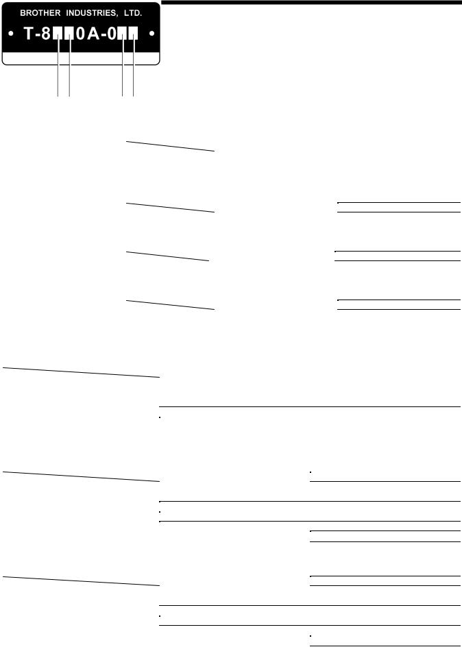
...T-8420B
TWIN NEEDLE LOCK STITCHER
T-8450B
TWIN NEEDLE SPLIT NEEDLE BAR LOCK STITCHER
T-8720B
TWIN NEEDLE LOCK STITCHER WITH LARGE HOOK
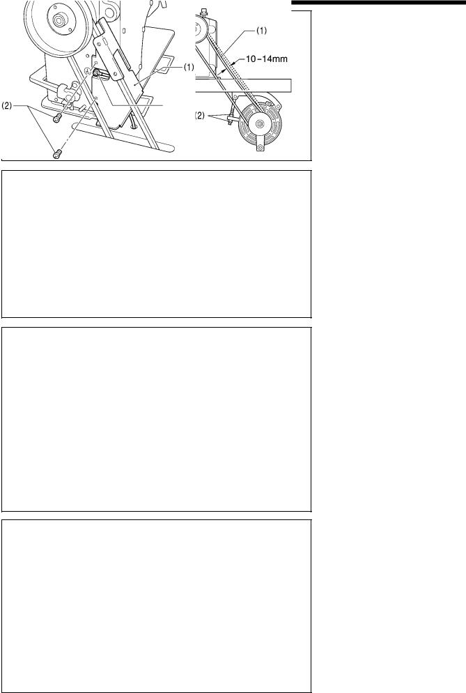
T-8750B
TWIN NEEDLE SPLIT NEEDLE BAR LOCK STITCHER
WITH LARGE HOOK

Thank you very much for buying a BROTHER sewing machine. Before using your new machine, please read the safety instructions below and the explanations given in the instruction manual.
With industrial sewing machines, it is normal to carry out work while positioned directly in front of moving parts such as the needle and thread take-up, and consequently there is always a danger of injury that can be caused by these parts. Follow the instructions from training personnel and instructors regarding safe and correct operation before operating the machine so that you will know how to use it correctly.
SAFETY INSTRUCTIONS
1. Safety indications and their meanings
This instruction manual and the indications and symbols that are used on the machine itself are provided in order to ensure safe operation of this machine and to prevent accidents and injury to yourself or other people.
Indications
 CAUTION
Symbols
The instructions which follow this term indicate situations where failure to follow the instructions could cause injury when using the machine or physical damage to equipment and surroundings.
 · · · · ·
 · · · · ·
 · · · · ·
This symbol (  ) indicates something that you should be careful of. The picture inside the triangle indicates the nature of the caution that must be taken.
(For example, the symbol at left means “beware of injury”.)
This symbol (  ) indicates something that you must not do.
This symbol (  ) indicates something that you must do. The picture inside the circle indicates the nature of the thing that must be done.
(For example, the symbol at left means “you must make the ground connection”.)
T-8420B, 8450B, 8720B, 8750B |
i |
2. Notes on safety
 CAUTION
Environmental requirements
Use the sewing machine in an area which is free |
The ambient temperature should be within the |
|
from sources of strong electrical noise such as |
range of 5°C to 35°C during use. |
|
electrical line noise or static electric noise. |
Temperatures which are lower or higher than this |
|
Sources of strong electrical noise may cause |
may cause problems with correct operation. |
|
problems with correct operation. |
The relative humidity should be within the range of |
|
Any fluctuations in the power supply voltage |
||
45% to 85% during use, and no dew formation |
||
should be within ±10% of the rated voltage for the |
should occur in any devices. |
|
machine. |
Excessively dry or humid environments and dew |
|
Voltage fluctuations which are greater than this |
formation may cause problems with correct |
|
may cause problems with correct operation. |
operation. |
|
The power supply capacity should be greater than |
In the event of an electrical storm, turn off the power |
|
the requirements for the sewing machine's power |
and disconnect the power cord from the wall outlet. |
|
consumption. |
Lightning may cause problems with correct |
|
Insufficient power supply capacity may cause |
operation. |
|
problems with correct operation. |
|
Installation
Machine installation should only be carried out by a qualified technician.
Contact your Brother dealer or a qualified electrician for any electrical work that may need to be done.
The sewing machine weighs approximately 43 kg. The installation should be carried out by two or more people.
Do not connent the power cord until installation is complete. The machine may operate if the treadle is depressed by mistake, which could result in injury.
Be sure to connect the ground. If the ground connection is not secure, you run a high risk of receiving a serious electric shock, and problems with correct operation may also occur.
All cords should be secured at least 25 mm away from any moving parts. Furthermore, do not excessively bend the cords or secure them too firmly with staples, otherwise there is the danger that fire or electric shocks could occur.
If using a work table which has casters, the casters should be secured in such a way so that they cannot move.
Use both hands to hold the machine head when tilting it back or returning it to its original position. If only one hand is used, the weight of the machine head may cause your hand to slip, and your hand may get caught.
Be sure to wear protective goggles and gloves when handling the lubricating oil and grease, so that they do not get into your eyes or onto your skin, otherwise inflammation can result.
Furthermore, do not drink the oil or eat the grease under any circumstances, as they can cause vomiting and diarrhea.
Keep the oil out of the reach of children.
ii |
T-8420B, 8450B, 8720B, 8750B |
 CAUTION
Sewing
This sewing machine should only be used by operators who have received the necessary training in safe use beforehand.
The sewing machine should not be used for any applications other than sewing.
Be sure to wear protective goggles when using the machine.
If goggles are not worn, there is the danger that if a needle breaks, parts of the broken needle may enter your eyes and injury may result.
Turn off the power switch at the following times. The motor will keep turning even after the power is switched off as a result of the motor’s inertia. Wait until the motor stops fully before starting work. The machine may operate if the treadle is depressed by mistake, which could result in injury.
yWhen threading the needle
yWhen replacing the bobbin and needle
yWhen not using the machine and when leaving the machine unattended
If using a work table which has casters, the casters should be secured in such a way so that they cannot move.
Attach all safety devices before using the sewing machine. If the machine is used without these devices attached, injury may result.
Do not touch any of the moving parts or press any objects against the machine while sewing, as this may result in personal injury or damage to the machine.
Use both hands to hold the machine head when tilting it back or returning it to its original position. If only one hand is used, the weight of the machine head may cause your hand to slip, and your hand may get caught.
If an error occurs in machine, or if abnormal noises or smells are noticed, immediately turn off the power switch. Then contact your nearest Brother dealer or a qualified technician.
If the machine develops a problem, contact your nearest Brother dealer or a qualified technician.
Cleaning
Turn off the power switch before carrying out cleaning.
The motor will keep turning even after the power is switched off as a result of the motor’s inertia. Wait until the motor stops fully before starting work. The machine may operate if the treadle is depressed by mistake, which could result in injury.
Use both hands to hold the machine head when tilting it back or returning it to its original position. If only one hand is used, the weight of the machine head may cause your hand to slip, and your hand may get caught.
Be sure to wear protective goggles and gloves when handling the lubricating oil and grease, so that they do not get into your eyes or onto your skin, otherwise inflammation can result.
Furthermore, do not drink the oil or eat the grease under any circumstances, as they can cause vomiting and diarrhea.
Keep the oil out of the reach of children.
Use only the proper replacement parts as specified by Brother.
T-8420B, 8450B, 8720B, 8750B |
iii |
3.Warning labels
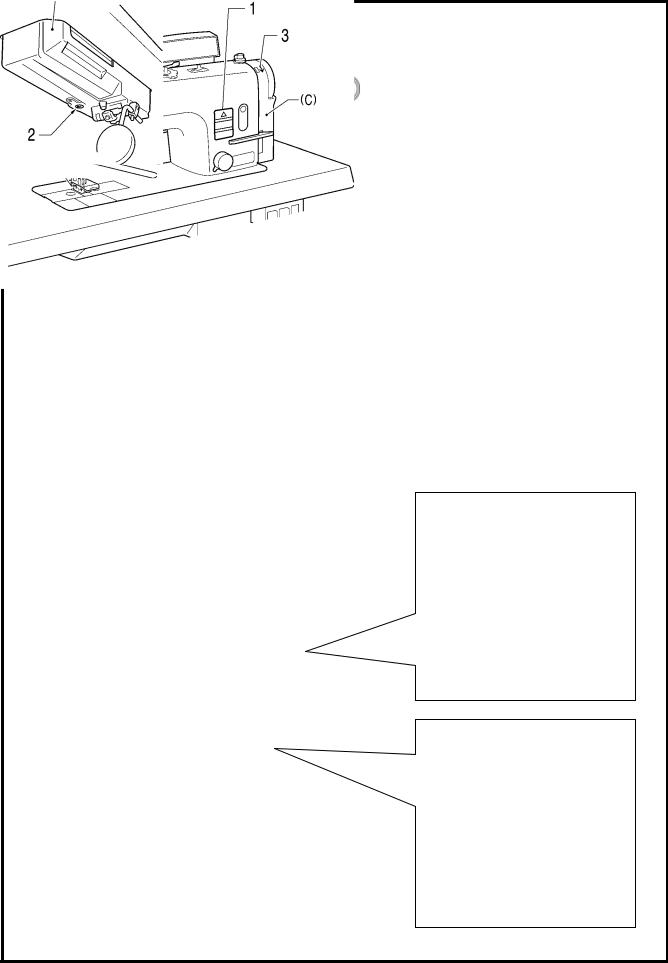
The following warning labels appear on the sewing machine.
Please follow the instructions on the labels at all times when using the machine. If the labels have been removed or are difficult to read, please contact your nearest Brother dealer.
1 |
2 |
|
Be sure to connect the ground. If the ground |
|
connection is not secure, you run a high risk of |
||
|
|
|
receiving a serious electric shock, and problems |
|
|
|
with correct operation may also occur. |
|
3 |
|
Direction of operation |
|
|
||
|
|
|
|
Safety devices:
(A)Finger guard
(B)Thread take-up cover
(C)Belt cover
2955M
Oil pan
2956M
2954M
iv T-8420B, 8450B, 8720B, 8750B
CONTENTS
1. |
NAMES OF MAJOR PARTS................ |
1 |
2. |
MACHINE SPECIFICATIONS.............. |
2 |
3. |
TABLE AND MOTOR........................... |
3 |
4. |
INSTALLATION ................................... |
4 |
4-1. Installation ...................................................... |
5 |
|
4-2. Lubrication...................................................... |
11 |
|
4-3. Checking the machine pulley rotating direction .... |
13 |
|
4-4. Alarm display (Semi dry type) ........................ |
13 |
|
5. |
PREPARATION BEFORE SEWING .... |
14 |
5-1. Installing the needle ....................................... |
14 |
|
5-2. Removing the bobbin ..................................... |
15 |
|
5-3. Winding the lower thread ............................... |
16 |
|
5-4. Installing the bobbin ....................................... |
17 |
|
5-5. Threading the upper thread............................ |
19 |
|
5-6. Adjusting the stitch length .............................. |
21 |
|
5-7. Using the knee lifter ....................................... |
21 |
|
5-8. Corner sewing method (T-8450B, 8750B)...... |
22 |
|
|
5-8-1. To stop the needle bars |
|
|
(right and left) ...................................... |
22 |
|
5-8-2. Number of stitches: quick-reference |
|
|
guide.................................................... |
22 |
6. SEWING ............................................... |
23 |
|
6-1. Sewing............................................................ |
23 |
|
6-2. Backtacking .................................................... |
23 |
|
6-3. Sewing condensed stitches ............................ |
24 |
|
7. THREAD TENSION .............................. |
25 |
|
7-1. Adjusting the thread tension ........................... |
25 |
|
7-2. Adjusting the presser foot pressure ................ |
26 |
|
7-3. |
Adjusting the thread take-up amount.............. |
27 |
8. CLEANING ........................................... |
28 |
|
8-1. |
Daily cleaning procedures .............................. |
28 |
8-2. |
Lubricating via the oil cover |
|
|
(every 6 months)............................................. |
29 |
8-3. |
Applying grease - When the GREASE |
|
|
indicator illuminates (Semi dry type)............... |
30 |
9. ADJUSTING THE ROTARY HOOK |
|
|
LUBRICATION AMOUNT .................... |
33 |
|
10. TROUBLESHOOTING ....................... |
34 |
|
T-8420B, 8450B, 8720B, 8750B
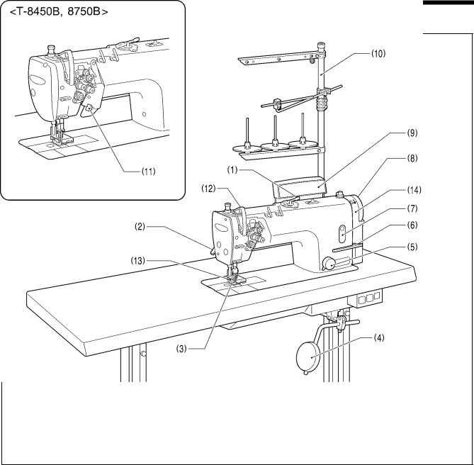
1. NAMES OF MAJOR PARTS
1. NAMES OF MAJOR PARTS
2957M
(1) |
Bobbin winder |
(2) |
Lifting lever |
(3) |
Presser foot |
(4) |
Knee lifter assembly |
(5) |
Stitch length dial |
(6) |
Reverse lever |
(7) |
Oil gauge window |
(8) |
Machine pulley |
(9) |
Alarm display (semi dry type) |
(10) |
Cotton stand |
(11)Stop lever (T-8450B, 8750B)
Safety devices |
|
|
(12) |
Thread take-up cover |
(13) Finger guard |
(14) |
Belt cover |
|
1 |
T-8420B, 8450B, 8720B, 8750B |
2. MACHINE SPECIFICATIONS
2. MACHINE SPECIFICATIONS
|
|
|
|
|
|
|
|
|
|
|
|
|
|
|
|
|
|
|
|
|
|
|
|
|
|
|
|
|
|
|
|
|
|
|
|
|
|
|
|
|
|
|
|
|
|
|
|
|
|
|
|
|
|
|
|
|
|
|
|
|
|
|
|
F |
|
|
|
3 |
|
|
|
|
|
|
5 |
||
|
|
|
|
|
|
|
|
|
|
|
|
|
|
|
For light-weight and |
|
For heavy-weight |
||||||||
|
|
|
|
|
|
|
Use |
|
For foundation |
|
mediumweight |
|
|
||||||||||||
|
|
|
|
|
|
|
|
|
|
|
|
|
materials |
||||||||||||
|
|
|
|
|
|
|
|
|
|
|
|
|
|
|
|
materials |
|
|
|
|
|
||||
|
|
|
|
|
|
|
|
|
|
|
|
|
|
|
|
|
|
|
|
|
|
||||
|
|
|
|
|
|
|
|
|
|
|
|
|
|
|
|
|
|
|
|
|
|
3 |
|
||
|
|
|
|
|
|
|
|
|
|
|
|
|
|
|
|
|
|
|
|
|
|
|
|||
|
|
|
|
|
|
|
|
|
|
|
0 |
|
|
|
|
|
|
|
|
|
|
||||
|
|
|
|
|
|
Lubrication type |
|
Minimum lubrication |
|
|
|
|
|
|
Semi dry |
||||||||||
|
|
|
|
|
|
|
|
|
|
|
|
|
|
|
|
|
|
|
|
|
|
5 |
|
|
|
|
|
|
|
|
|
|
|
|
|
|
|
|
|
|
|
|
|
|
|
|
|
|
|
||
|
|
|
|
|
|
|
|
|
|
|
2 |
|
|
|
|
|
|
|
|
|
|
|
|||
|
|
|
|
|
|
Stitch function |
|
|
Fixed needle bar |
|
|
|
|
Split needle bar |
|||||||||||
|
|
|
|
|
|
|
|
|
|
|
|
|
|
|
|
|
|
|
|
|
|
7 |
|
||
|
|
|
|
|
|
|
|
|
|
|
|
|
|
|
|
|
|
|
|
|
|
|
|||
|
|
|
|
|
|
|
|
|
|
|
4 |
|
|
|
|
|
|
|
|
|
|
||||
|
|
|
|
|
Rotary hook |
|
Standard hook |
|
|
|
|
|
|
Large hook |
|||||||||||
T-8420B |
|
|
|
|
|
|
|
|
|
|
|
|
|
|
|
|
|
|
|
|
|
|
|
||
|
|
|
|
|
|
|
-00F |
|
-03F |
|
-003 |
|
|
|
-033 |
|
-005 |
||||||||
Max. sewing speed |
|
|
4,000 rpm |
|
3,000 rpm |
|
4,000 rpm |
|
|
3,000 rpm |
|
3,000 rpm |
|||||||||||||
Max. stitch length |
|
|
|
|
|
|
|
|
|
4 |
mm |
|
|
|
|
|
|
|
|
|
|
|
5 mm |
||
Presser foot |
|
Lifting lever |
|
|
|
|
|
|
|
|
|
|
7 mm |
|
|
|
|
|
|
|
|
|
|||
height |
|
Knee lifter |
|
|
|
|
|
|
|
|
|
|
13 mm |
|
|
|
|
|
|
|
|
|
|||
Feed dog height |
|
|
|
|
|
|
|
|
|
|
|
|
|
1 mm |
|
|
|
|
|
|
|
|
|
||
Needle (DP×5) |
|
|
|
|
|
|
#9–#14 |
|
|
|
#11–#16 |
|
|
|
|
|
#14–#22 |
||||||||
T-8720B, 8750B |
|
|
|
|
|
|
|
|
|
|
|
|
|
|
|
|
|
|
|
-005 |
|
|
|||
|
|
|
|
|
|
|
|
|
|
|
-003 |
|
|
|
rpm |
|
|
|
|
|
|
|
|||
Max. sewing speed |
|
|
|
|
|
|
|
|
|
3,000 |
|
|
|
|
|
|
|
|
|
||||||
Max. stitch length |
|
|
|
|
|
|
|
|
|
|
|
|
7 mm |
|
|
|
|
|
|
|
|
|
|||
Presser foot |
|
Lifting lever |
|
|
|
|
|
|
|
|
|
|
7 mm |
|
|
|
|
|
|
|
|
|
|||
height |
|
Knee lifter |
|
|
|
|
|
|
|
|
|
|
13 mm |
|
|
|
|
|
|
|
|
|
|||
Feed dog height |
|
|
|
|
|
|
|
|
|
|
|
|
|
1 mm |
|
|
|
|
#14–#22 |
|
|||||
Needle (DP×5) |
|
|
|
|
|
|
|
|
#11–#16 |
|
|
|
|
|
|
|
|
||||||||
T-8450B |
|
|
|
|
|
|
|
|
|
|
|
|
|
|
|
|
|
|
|
-005 |
|
|
|||
|
|
|
|
|
|
|
|
|
|
|
-003 |
|
|
|
rpm |
|
|
|
|
|
|
|
|||
Max. sewing speed |
|
|
|
|
|
|
|
|
|
3,000 |
|
|
|
|
|
|
|
|
|
||||||
Max. stitch length |
|
|
|
|
|
|
|
|
|
|
|
|
5 mm |
|
|
|
|
|
|
|
|
|
|||
Presser foot |
|
Lifting lever |
|
|
|
|
|
|
|
|
|
|
7 mm |
|
|
|
|
|
|
|
|
|
|||
height |
|
Knee lifter |
|
|
|
|
|
|
|
|
|
|
13 mm |
|
|
|
|
|
|
|
|
|
|||
Feed dog height |
|
|
|
|
|
|
|
|
|
|
|
|
|
1 mm |
|
|
|
|
#14–#22 |
|
|||||
Needle (DP×5) |
|
|
|
|
|
|
|
|
#11–#16 |
|
|
|
|
|
|
|
|
||||||||
T-8420B, 8450B, 8720B, 8750B |
2 |
3. TABLE AND MOTOR
3. TABLE AND MOTOR
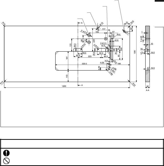
A. Table processing diagram
yThe top of the table should be 40 mm in thickness and should be strong enough to hold the weight and with-stand the vibration of the sewing machine.
yDrill holes as indicated in the illustration below.
Cotton stand hole
Ground wire hole
Head rest hole
Motor mounting holes
2958M
B. Motor
 CAUTION
All cords should be secured at least 25 mm away from any moving parts. Furthermore, do not excessively bend the cords or secure them too firmly with staples, otherwise there is the danger that fire or electric shocks could occur.
<Motor>
Use one of the clutch motors given in the table at right as the motor.
Refer to the instruction manual for the motor for details on installing and using the motor.
Power |
Motor |
Single-phase |
2-pole, 400 W motor |
Three-phase |
2-pole, 400 W motor |
<Motor pulley and V-belt>
Select the correct motor pulley and V-belt by referring to the table below to suit the power frequency of your area.
Sewing speed |
Frequency |
Motor pulley (Outer diameter) |
V-belt |
|
4,000 rpm |
50 Hz |
Motor pulley 100 |
46 |
|
60 Hz |
Motor pulley 85 |
45 |
||
|
||||
3,500 rpm |
50 Hz |
Motor pulley 90 |
45 |
|
60 Hz |
Motor pulley 70 |
44 |
||
|
||||
3,000 rpm |
50 Hz |
Motor pulley 75 |
44 |
|
60 Hz |
Motor pulley 65 |
43 |
||
|
3 |
T-8420B, 8450B, 8720B, 8750B |
|
|
|
4. INSTALLATION |
||||
|
|
|
|
|
|
|
|
4. INSTALLATION |
|
|
|
|
|
|
|
CAUTION |
|
|
|
|
|
|
|
Machine installation should only be carried out by a |
Use both hands to hold the machine head when |
|
|||||
qualified technician. |
tilting it back or returning it to its original position. If |
|
|||||
Contact your Brother dealer or a qualified electrician |
only one hand is used, the weight of the machine |
|
|||||
head may cause your hand to slip, and your hand |
|
||||||
for any electrical work that may need to be done. |
|
||||||
may get caught. |
|
|
|
|
|
||
The sewing machine weighs approximately 43 kg. |
|
|
|
|
|
||
Be sure to |
connect the |
ground. |
If |
the |
ground |
|
|
The installation should be carried out by two or more |
|
||||||
connection is |
not secure, |
you run |
a |
high |
risk of |
|
|
people. |
|
||||||
receiving a serious electric shock, and problems with |
|
||||||
Do not connect the power cord until installation is |
|
||||||
correct operation may also occur. |
|
|
|
|
|||
complete. The machine may operate if the treadle is |
|
|
|
|
|
|
|
depressed by mistake, which could result in injury. |
|
|
|
|
|
|
|
Carrying the machine
yThe machine should be carried by the arm by two people as shown in the illustration.
*Make sure that the machine pulley does not turn.
2959M
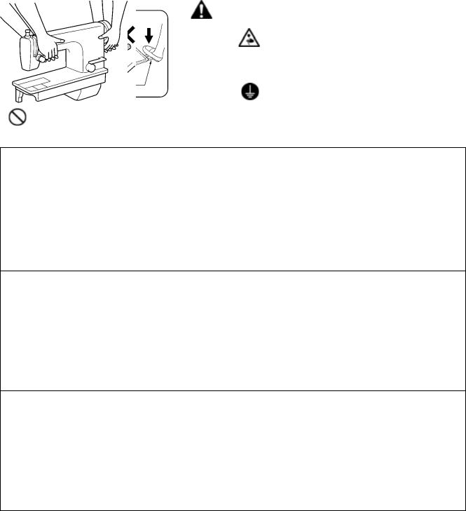
Tilting back the machine head
yHold section (B) with your foot so that the table does not move, and then push the arm with both hands to tilt back the machine head.
2871M
Returning the machine head to the upright position
1.Clear away any tools, etc. which may be near the table holes.
2.While holding the face plate with your left hand, gently return the machine head to the upright position with your right hand.
2872M
T-8420B, 8450B, 8720B, 8750B |
4 |

4. INSTALLATION
4-1. Installation
1. Oil pan
(1) Head cushions (left) [2 pcs]
(2) Head cushions (right) [2 pcs]
(3) Oil pan
(4) Oiler
2874M
2. Rubber cushions
(1) Rubber cushions [2 pcs]
(2) Nails [4 pcs]
3. Knee lifter complying bar
(3) Knee lifter complying bar
2875M
4. Machine head
(1) Hinges [2 pcs]
(2) Machine head
(3) Head rest
NOTE:
Tap the head rest (3) securely into the table hole. If the head rest (3) is not pushed in as far as it will go, the machine head will not be sufficiently stable when it is tilted back.
2960M
5 |
T-8420B, 8450B, 8720B, 8750B |
4. INSTALLATION
5. Knee lifter plate
(1)Knee lifter plate
(2)Bolt
*Loosen the bolt (3) and the bolt (4), and move the knee lifter plate (1) to a position where it is easy to use.
2961M
2962M
2881M
<Knee lifter adjustment>
1.Turn the machine pulley so that the feed dog is below the top of the needle plate.
2.Lower the presser foot (5) by using the lifting lever (4).
3.Loosen the nut (6).
4.Turn the screw (8) to adjust so that the amount of play in the knee lifter (7) is approximately 2 mm when the knee lifter plate (1) is gently pressed.
5.Securely tighten the nut (6).
6.Loosen the nut (9).
7.Turn the screw (10) until the distance between the end of the screw (10) and the knee lifter (7) is approximately 5 mm.
8.Turn the adjusting screw (10) to adjust so that the presser foot (5) is at the desired position within a distance of 13 mm of the needle plate when the knee liter plate (1) is fully pressed.
9.After adjustment is completed, securely tighten the nut (9).
Within 13 mm
2963M
T-8420B, 8450B, 8720B, 8750B |
6 |
4. INSTALLATION
Ground symbol
Align horizontally to the right and then tighten.
Motor 2964M
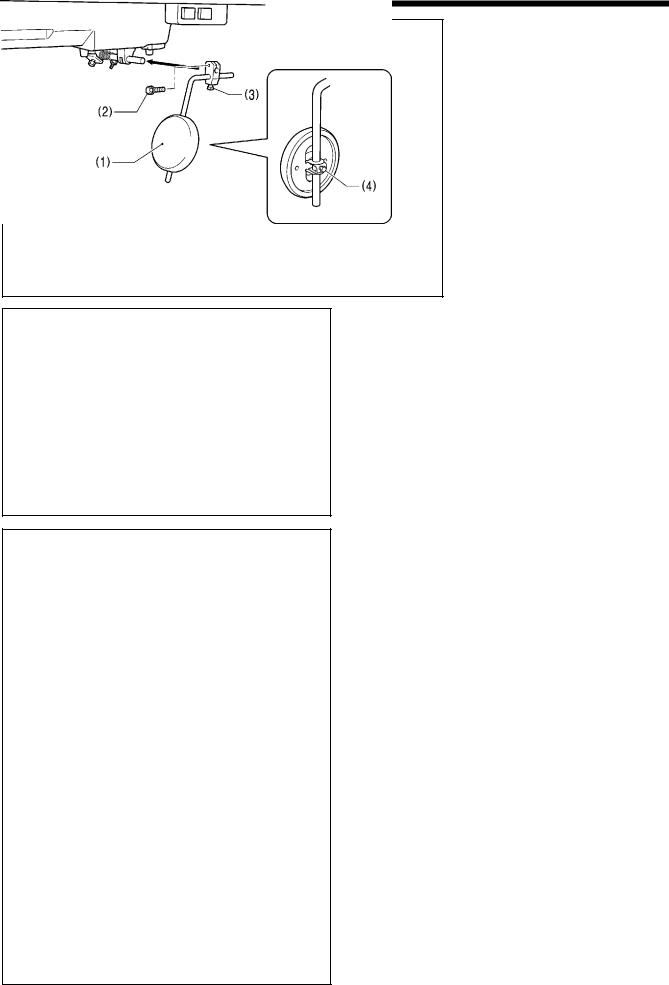
6. Ground wire
(1)Ground wire
(2)Screw
<Semi dry type>
Be sure to connect the accessory ground wire (1) to the motor.
< Minimum lubrication type>
Use a suitable ground wire.
Oil pan
Ground symbol
Motor
7. Ground wire
Use a suitable ground wire.
(1)Ground wire
(2)Screw
2965M
8. V-belt
(1) V-belt
Turn the two nuts (2) to adjust so that there is 10-14 mm of deflection in the V-belt (1) when it is pressed at the midway point with a force of 5 N.
2966M
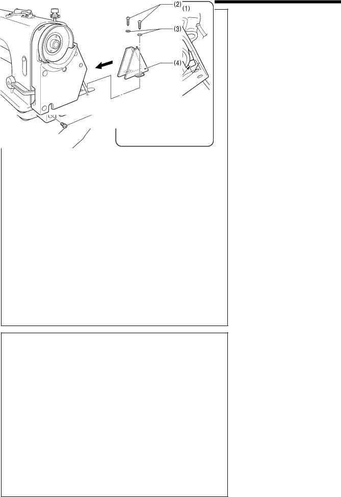
9. Belt cover bracket
(1)Belt cover bracket
(2)Screws [2 pcs]
Ground wire
2967M
7 |
T-8420B, 8450B, 8720B, 8750B |
4. INSTALLATION
2968M
Insert the projecting part underneath the machine pulley.
2969M
2970M
10. Belt cover U
(1)Belt cover U
(2)Screws [4 pcs]
11. Belt cover D
(1)Belt cover D
(2)Wood screws [2 pcs]
(3)Washers [2 pcs]
T-8420B, 8450B, 8720B, 8750B |
8 |
Loading...