


 Loading...
INSTRUCTION MANUAL
T-8421C, 8422C
T-8452C, 8722C T-8752C
Please read this manual before using the machine.
Please keep this manual within easy reach for quick reference.
TWIN NEEDLE DIRECT DRIVE LOCK STITCHER
Thank you very much for buying a BROTHER sewing machine. Before using your new machine, please read the safety instructions below and the explanations given in the instruction manual.
With industrial sewing machines, it is normal to carry out work while positioned directly in front of moving parts such as the needle and thread take-up, and consequently there is always a danger of injury that can be caused by these parts. Follow the instructions from training personnel and instructors regarding safe and correct operation before operating the machine so that you will know how to use it correctly.

SAFETY INSTRUCTIONS
[1] Safety indications and their meanings
This instruction manual and the indications and symbols that are used on the machine itself are provided in order to ensure safe operation of this machine and to prevent accidents and injury to yourself or other people.
Indications
 DANGER
 CAUTION
Symbols
The instructions which follow this term indicate situations where failure to follow the instructions may result in death or serious injury.
The instructions which follow this term indicate situations where failure to follow the instructions could cause injury when using the machine or physical damage to equipment and surroundings.
 · · · · ·
 · · · · ·
 · · · · ·
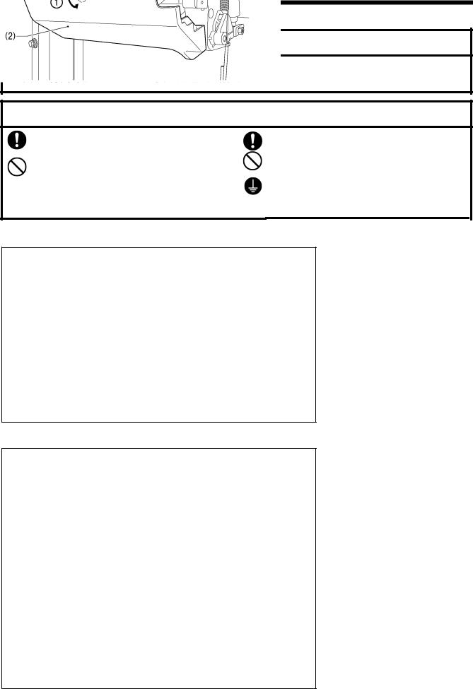
This symbol (  ) indicates something that you should be careful of. The picture inside the triangle indicates the nature of the caution that must be taken.
(For example, the symbol at left means “beware of injury”.)
This symbol (  ) indicates something that you must not do.
This symbol (  ) indicates something that you must do. The picture inside the circle indicates the nature of the thing that must be done.
(For example, the symbol at left means “you must make the ground connection”.)
T-8421C, 8422C, 8452C, 8722C, 8752C |
i |
[2] Notes on safety
 DANGER
Wait at least 5 minutes after turning off the power switch and disconnecting the power cord from the wall outlet before opening the cover of the control box. Touching areas where high voltages are present can result in severe injury.
 CAUTION
Environmental requirements
Use the sewing machine in an area which is free from sources of strong electrical noise such as electrical line noise or static electric noise.
Sources of strong electrical noise may cause problems with correct operation.
Any fluctuations in the power supply voltage should be within ±10% of the rated voltage for the machine.
Voltage fluctuations which are greater than this may cause problems with correct operation.
The power supply capacity should be greater than the requirements for the sewing machine's power consumption.
Insufficient power supply capacity may cause problems with correct operation.
The ambient temperature should be within the range of 5°C to 35°C during use.
Temperatures which are lower or higher than this may cause problems with correct operation.
The relative humidity should be within the range of 45% to 85% during use, and no dew formation should occur in any devices.
Excessively dry or humid environments and dew formation may cause problems with correct operation.
In the event of an electrical storm, turn off the power and disconnect the power cord from the wall outlet. Lightning may cause problems with correct operation.
Installation
Machine installation should only be carried out by a qualified technician.
Contact your Brother dealer or a qualified electrician for any electrical work that may need to be done.
The sewing machine weighs approximately 50 kg (110 lb). The installation should be carried out by two or more people.
Do not connect the power cord until installation is complete. The machine may operate if the treadle is depressed by mistake, which could result in injury.
Turn off the power switch before inserting or removing the plug, otherwise damage to the control box could result.
Be sure to connect the ground. If the ground connection is not secure, you run a high risk of receiving a serious electric shock, and problems with correct operation may also occur.
When securing the cords, do not bend the cords excessively or fasten them too hard with staples, otherwise there is the danger that fire or electric shocks could occur.
If using a work table which has casters, the casters should be secured in such a way so that they cannot move.
Secure the table so that it will not move when tilting back the machine head. If the table moves, it may crush your feet or cause other injuries.
Use both hands to hold the machine head when tilting it back or returning it to its original position. If only one hand is used, the weight of the machine head may cause your hand to slip, and your hand may get caught.
Be sure to wear protective goggles and gloves when handling the lubricating oil and grease, so that they do not get into your eyes or onto your skin, otherwise inflammation can result.
Furthermore, do not drink the oil or eat the grease under any circumstances, as they can cause vomiting and diarrhea.
Keep the oil out of the reach of children.
ii |
T-8421C, 8422C, 8452C, 8722C, 8752C |
 CAUTION
Sewing
This sewing machine should only be used by operators who have received the necessary training in safe use beforehand.
The sewing machine should not be used for any applications other than sewing.
Be sure to wear protective goggles when using the machine.
If goggles are not worn, there is the danger that if a needle breaks, parts of the broken needle may enter your eyes and injury may result.
Turn off the power switch at the following times. The machine may operate if the treadle is depressed by mistake, which could result in injury.
yWhen threading the needle
yWhen replacing the bobbin and needle
yWhen not using the machine and when leaving the machine unattended
If using a work table which has casters, the casters should be secured in such a way so that they cannot move.
Attach all safety devices before using the sewing machine. If the machine is used without these devices attached, injury may result.
Do not touch any of the moving parts or press any objects against the machine while sewing, as this may result in personal injury or damage to the machine.
Secure the table so that it will not move when tilting back the machine head. If the table moves, it may crush your feet or cause other injuries.
Use both hands to hold the machine head when tilting it back or returning it to its original position. If only one hand is used, the weight of the machine head may cause your hand to slip, and your hand may get caught.
If an error occurs in machine operation, or if abnormal noises or smells are noticed, immediately turn off the power switch. Then contact your nearest Brother dealer or a qualified technician.
If the machine develops a problem, contact your nearest Brother dealer or a qualified technician.
Cleaning
Turn off the power switch before carrying out cleaning. The machine may operate if the treadle is depressed by mistake, which could result in injury.
Secure the table so that it will not move when tilting back the machine head. If the table moves, it may crush your feet or cause other injuries.
Use both hands to hold the machine head when tilting it back or returning it to its original position. If only one hand is used, the weight of the machine head may cause your hand to slip, and your hand may get caught.
Be sure to wear protective goggles and gloves when handling the lubricating oil and grease, so that they do not get into your eyes or onto your skin, otherwise inflammation can result.
Furthermore, do not drink the oil or eat the grease under any circumstances, as they can cause vomiting and diarrhea.
Keep the oil out of the reach of children.
Use only the proper replacement parts as specified by Brother.
Maintenance and inspection
Maintenance and inspection of the sewing machine should only be carried out by a qualified technician.
Ask your Brother dealer or a qualified electrician to carry out any maintenance and inspection of the electrical system.
Turn off the power switch and disconnect the power cord from the wall outlet at the following times, otherwise the machine may operate if the treadle is depressed by mistake, which could result in injury.
yWhen carrying out inspection, adjustment and maintenance
yWhen replacing consumable parts such as the rotary hook
If the power switch needs to be left on when carrying out some adjustment, be extremely careful to observe all safety precautions.
Secure the table so that it will not move when tilting back the machine head. If the table moves, it may crush your feet or cause other injuries.
Use both hands to hold the machine head when tilting it back or returning it to its original position.
If only one hand is used, the weight of the machine head may cause your hand to slip, and your hand may get caught.
Use only the proper replacement parts as specified by Brother.
If any safety devices have been removed, be absolutely sure to re-install them to their original positions and check that they operate correctly before using the machine.
Any problems in machine operation which result from unauthorized modifications to the machine will not be covered by the warranty.
T-8421C, 8422C, 8452C, 8722C, 8752C |
iii |

[3] Warning labels
The following warning labels appear on the sewing machine.
Please follow the instructions on the labels at all times when using the machine. If the labels have been removed or are difficult to read, please contact your nearest Brother dealer.
1
2 
Touching areas where high voltages are present can |
4 |
Be careful not to get your hands |
result in severe injury. Turn off the power before |
caught when returning the |
|
opening the cover. |
|
machine head to its original |
|
|
position after it has been tilted. |
3
*Safety devices: (A) Finger guard
(B)Thread take-up cover
5 |
|
Be careful |
to |
avoid injury from |
|
the moving thread take-up. |
|||
|
|
|||
6 |
|
Be sure to connect the ground. If |
||
|
||||
|
the ground connection is not |
|||
|
|
secure, you run a high risk of |
||
|
PE |
receiving |
a |
serious electric |
|
shock, and problems with correct |
|||
|
|
operation may also occur. |
7 |
|
Direction of operation |
|
||
|
|
|
8 |
|
|
|
|
iv |
T-8421C, 8422C, 8452C, 8722C, 8752C |
Oil pan
Control box
Transformer box (100V/400V system only)
2166B
|
2506B |
|
Oil tank |
||
|
T-8421C, 8422C, 8452C, 8722C, 8752C |
v |
CONTENTS
1. MACHINE SPECIFICATIONS .............. |
1 |
2. NAMES OF MAJOR PARTS ................ |
3 |
3. INSTALLATION.................................... |
4 |
3-1. Table processing diagram .............................. |
5 |
3-2. Installation ...................................................... |
5 |
3-3. Lubrication ...................................................... |
9 |
3-4. Connecting the cords...................................... |
11 |
3-4-1. Opening the control box cover ............ |
11 |
3-4-2. Connecting the cords .......................... |
11 |
3-5. Test operation (Operating the treadle) ........... |
16 |
3-6. Adjusting the treadle operation....................... |
17 |
4. PREPARATION BEFORE SEWING..... |
18 |
4-1. Installing the needle........................................... |
18 |
4-2. Removing the bobbin...................................... |
19 |
4-3. Winding the lower thread................................ |
20 |
4-4. Installing the bobbin........................................ |
21 |
4-5. Threading the upper thread............................ |
23 |
4-6. Adjusting the stitch length............................... |
25 |
4-7. Using the knee lifter........................................ |
25 |
4-8. Using the thread wiper |
|
(models with thread trimmer only) .................. |
25 |
4-9. Corner sewing method (T-8452C, 8752C) ..... |
26 |
4-9-1. To stop the needle bars |
|
(right and left) ..................................... |
26 |
4-9-2. Number of stitches: quick-reference |
|
guide ................................................... |
26 |
5. USING THE G50 OPERATION PANEL |
|
(BASIC OPERATIONS) ........................ |
27 |
5-1. Names and functions...................................... |
27 |
5-2. Sewing start and end backtack stitches ......... |
29 |
5-3. Sewing continuous backtack stitches............. |
30 |
5-4. Sewing fixed stitches ...................................... |
31 |
5-5. Sewing pleat presser stitches......................... |
32 |
5-6. Using the lower thread counter ...................... |
33 |
6. USING THE G50 OPERATION PANEL |
|
(ADVANCED OPERATIONS)............... |
34 |
6-1. Names and functions ...................................... |
34 |
6-2. Adjusting the needle up stop position ............. |
35 |
6-3. LOCK key........................................................ |
36 |
6-4. Resetting all settings to their defaults ............. |
37 |
7. USING THE G10 OPERATION PANEL |
|
(BASIC OPERATIONS)........................ |
38 |
7-1. Names and functions ...................................... |
38 |
7-2. Sewing start and end backtack stitches.......... |
39 |
7-3. Sewing continuous backtack stitches ............. |
40 |
8. USING THE G10 OPERATION PANEL |
|
(ADVANCED OPERATIONS)............... |
41 |
8-1. Changing the needle stop position ................. |
41 |
8-2. Slow start ........................................................ |
42 |
8-3. Correction sewing ........................................... |
43 |
8-4. Thread trimming lock |
|
(models with thread trimmer only)................... |
44 |
8-5. Setting the maximum sewing speed ............... |
45 |
8-6. Adjusting the needle up stop position ............. |
46 |
8-7. Lock function................................................... |
47 |
8-8. Resetting all settings to their defaults ............. |
47 |
9. SEWING ............................................... |
48 |
9-1. Sewing ............................................................ |
48 |
9-2. Backtacking..................................................... |
49 |
9-3. Sewing condensed stitches ............................ |
50 |
10. THREAD TENSION ............................ |
51 |
10-1. Adjusting the thread tension ......................... |
51 |
10-2. Adjusting the presser foot pressure .............. |
52 |
10-3. Adjusting the presser foot floating amount |
|
(minute lifting amount) .................................. |
53 |
10-4. Adjusting the trailing length after thread |
|
trimming (models with thread trimmer only) |
|
...................................................................... |
53 |
10-5. Adjusting the thread take-up amount............ |
54 |
T-8421C, 8422C, 8452C, 8722C, 8752C
11. CLEANING ......................................... |
55 |
11-1. Daily cleaning procedures ............................ |
55 |
11-2. Lubricating via the oil cover |
|
(every 6 months)........................................... |
56 |
11-3. Applying grease (Semi dry |
|
specifications) [When “GrUP” appears |
|
... When using the G50 operation panel]...... |
57 |
11-4. Applying grease (Semi dry |
|
specifications) [When “GrUP” appears |
|
... When using the G10 operation panel]...... |
60 |
12. ADJUSTING THE ROTARY HOOK |
|
LUBRICATION AMOUNT................... |
63 |
13. STANDARD ADJUSTMENT............... |
64 |
13-1. Safety switch position................................... |
64 |
13-2. Thread take-up amount for thread take-up |
|
spring............................................................ |
65 |
13-3. Thread take-up spring tension...................... |
66 |
13-4. Clearance between rotary hook and needle |
|
plate.............................................................. |
67 |
13-5. Clearance between rotary hook and |
|
opener .......................................................... |
68 |
13-6. Presser foot height ....................................... |
68 |
13-7. Needle and rotary hook timing ..................... |
69 |
13-8. Installing the feed dog .................................. |
71 |
13-9. Feed dog position ......................................... |
72 |
13-10. Feed dog height.......................................... |
73 |
13-11. Feed dog angle........................................... |
74 |
14. TROUBLESHOOTING........................ |
75 |
14-1. Sewing.......................................................... |
75 |
14-2. Error code displays....................................... |
80 |
15. 7-SEGMENT DISPLAY....................... |
84 |
T-8421C, 8422C, 8452C, 8722C, 8752C

1. MACHINE SPECIFICATIONS
1. MACHINE SPECIFICATIONS
2167B
A B C D E F
A |
|
4 |
7 |
|
Rotary hook |
Standard hook |
Large hook |
||
|
B |
|
2 |
5 |
|
Stitch function |
Fixed needle bar |
Split needle bar |
||
|
C |
|
1 |
2 |
|
Thread trimmer |
- |
○ |
||
|
D |
|
4 |
T |
Quick reverse |
○ |
○ |
|
|
Thread wiper |
○ |
- |
E |
|
0 |
3 |
|
Lubrication type |
Minimum lubrication |
Semi dry |
||
|
|
|
F |
3 |
5 |
7 |
|
F |
|
|
Light-weight and |
Heavy-weight |
Heavy-weight |
|
|
|
materials |
||||
Use |
Foundation |
medium-weight |
||||
|
materials |
(For extra thick |
||||
|
|
|
materials |
|||
|
|
|
|
thread) |
||
|
|
|
|
|
1 |
T-8421C, 8422C, 8452C, 8722C, 8752C |
1. MACHINE SPECIFICATIONS
T-8421C
|
|
|
|
|
|
-T3F |
|
|
|
-T0F |
|
-T33 |
-T03 |
|
Max. sewing speed |
|
|
3,000 sti/min |
|
4,000 sti/min |
|
3,000 sti/min |
4,000 sti/min |
||||||
Start |
backtacking |
and |
continuous |
|
|
|
|
250–1,800 sti/min |
|
|||||
backtacking speed |
|
|
|
|
|
|
|
|||||||
|
|
|
|
|
|
|
|
|
|
|
||||
End backtacking speed |
|
|
|
|
|
1,000 sti/min |
|
|||||||
Max. stitch length |
|
|
|
|
|
|
|
|
4 mm |
|
||||
Presser foot |
|
Lifting lever |
|
|
|
|
|
7 mm |
|
|||||
height |
|
|
Knee lifter |
|
|
|
|
|
|
13 mm |
|
|||
Feed dog height |
|
|
|
|
|
|
|
|
|
1 mm |
|
|||
Needle (DP×5) |
|
|
|
|
#9–#14 |
|
|
|
|
#11–#16 |
||||
Motor |
|
|
|
|
|
|
|
|
AC servo motor |
(4-pole, 550W) |
|
|||
Control circuit |
|
|
|
|
|
|
|
Microprocessor |
|
|||||
T-8422C |
|
|
|
|
|
|
|
|
|
|
-433 |
|
|
|
|
|
|
|
|
|
-403 |
|
|
|
|
|
-405, -407 |
||
Max. sewing speed |
|
|
4,000 sti/min |
|
|
|
3,000 |
sti/min |
|
|||||
Start |
backtacking |
and |
continuous |
|
|
|
|
250–1,800 sti/min |
|
|||||
backtacking speed |
|
|
|
|
|
|
|
|||||||
|
|
|
|
|
|
|
|
|
|
|
||||
End backtacking speed |
|
|
|
|
|
1,000 sti/min |
|
|||||||
Max. stitch length |
|
|
|
|
|
4 mm |
|
|
|
5 mm |
||||
Presser foot |
|
Lifting lever |
|
|
|
|
|
7 mm |
|
|
||||
height |
|
|
Knee lifter |
|
|
|
|
|
|
10 mm |
|
|||
Feed dog height |
|
|
|
|
|
|
|
|
|
1 mm |
|
|||
Needle (DP×5) |
|
|
|
|
|
#11–#16 |
|
|
|
#14–#22 |
||||
Motor |
|
|
|
|
|
|
|
|
AC servo motor (4-pole, 550W) |
|
||||
Control circuit |
|
|
|
|
|
|
|
Microprocessor |
|
|||||
T-8452C |
|
|
|
|
|
|
|
|
|
|
|
|
|
|
|
|
|
|
|
|
|
-403 |
|
|
|
-405, -407 |
|||
Max. sewing speed |
|
|
|
|
|
|
3,000 |
sti/min |
|
|||||
Start |
backtacking |
and |
continuous |
|
|
|
|
250–1,800 sti/min |
|
|||||
backtacking speed |
|
|
|
|
|
|
|
|||||||
|
|
|
|
|
|
|
|
|
|
|
||||
End backtacking speed |
|
|
|
|
|
1,000 sti/min |
|
|||||||
Max. stitch length |
|
|
|
|
|
|
|
|
5 mm |
|
||||
Presser foot |
|
Lifting lever |
|
|
|
|
|
7 mm |
|
|||||
height |
|
|
Knee lifter |
|
|
|
|
|
|
10 mm |
|
|||
Feed dog height |
|
|
|
|
|
|
|
|
|
1 mm |
|
|||
Needle (DP×5) |
|
|
|
#11–#16 |
|
|
|
|
#14–#22 |
|||||
Motor |
|
|
|
|
|
|
|
|
AC servo motor |
(4-pole, 550W) |
|
|||
Control circuit |
|
|
|
|
|
|
|
Microprocessor |
|
|||||
T-8722C, 8752C |
|
|
|
|
|
|
|
|
|
|
|
|
||
|
|
|
|
|
|
|
-403 |
|
|
|
-405, -407 |
|||
Max. sewing speed |
|
|
|
|
|
|
3,000 |
sti/min |
|
|||||
Start |
backtacking |
and |
continuous |
|
|
|
|
250–1,800 sti/min |
|
|||||
backtacking speed |
|
|
|
|
|
|
|
|||||||
|
|
|
|
|
|
|
|
|
|
|
||||
End backtacking speed |
|
|
|
|
|
1,000 sti/min |
|
|||||||
Max. stitch length |
|
|
|
|
|
|
|
|
7 mm |
|
||||
Presser foot |
|
Lifting lever |
|
|
|
|
|
7 mm |
|
|||||
height |
|
|
Knee lifter |
|
|
|
|
|
|
10 mm |
|
|||
Feed dog height |
|
|
|
|
|
|
|
|
|
1 mm |
|
|||
Needle (DP×5) |
|
|
|
#11–#16 |
|
|
|
|
#14–#22 |
|||||
Motor |
|
|
|
|
|
|
|
|
AC servo motor |
(4-pole, 550W) |
|
|||
Control circuit |
|
|
|
|
|
|
|
Microprocessor |
|
|||||
T-8421C, 8422C, 8452C, 8722C, 8752C |
2 |
2. NAMES OF MAJOR PARTS
2. NAMES OF MAJOR PARTS
G50 operation panel (advanced function LCD)
G10 operation panel (basic function LED)
2168B
(1) |
Bobbin winder |
(2) |
Thread wiper (T-8422C, 8452C, 8722C, 8752C) |
(3) |
Lifting lever |
(4) |
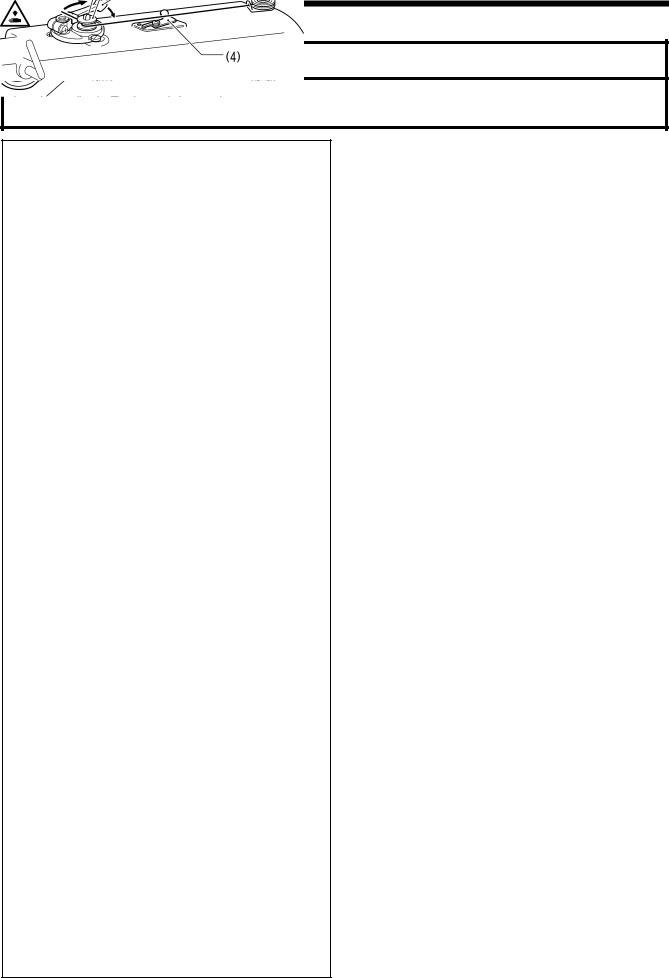
Quick reverse (Actuator switch) |
(5) |
Presser foot |
(6) |
Control box |
(7) |
Knee lifter assembly |
(8) |
Power switch |
(9) |
Stitch length dial |
(10) |
Reverse lever |
(11) |
Oil gauge window |
(12) |
Machine pulley |
(13) |
Operation panel |
(14) |
Cotton stand |
(15)Stop lever (T-8452C, 8752C )
Safety devices |
|
(16) Thread take-up cover |
(17) Finger guard |
3 |
T-8421C, 8422C, 8452C, 8722C, 8752C |
3. INSTALLATION
3. INSTALLATION
 CAUTION
Machine installation should only be carried out by a qualified technician.
Contact your Brother dealer or a qualified electrician for any electrical work that may need to be done.
The sewing machine weighs approximately 50 kg (110 lb). The installation should be carried out by two or more people.
Do not connect the power cord until installation is complete. The machine may operate if the treadle is depressed by mistake, which could result in injury.
Secure the table so that it will not move when tilting back the machine head. If the table moves, it may crush your feet or cause other injuries.
Use both hands to hold the machine head when tilting it back or returning it to its original position. If only one hand is used, the weight of the machine head may cause your hand to slip, and your hand may get caught.
About the machine set-up location
Do not set up this sewing machine near other equipment such as televisions, radios or cordless telephones, otherwise such equipment may be affected by electronic interference from the sewing machine.
The sewing machine should be plugged directly into an AC wall outlet. Operation problems may result if extension cords are used.
2086M
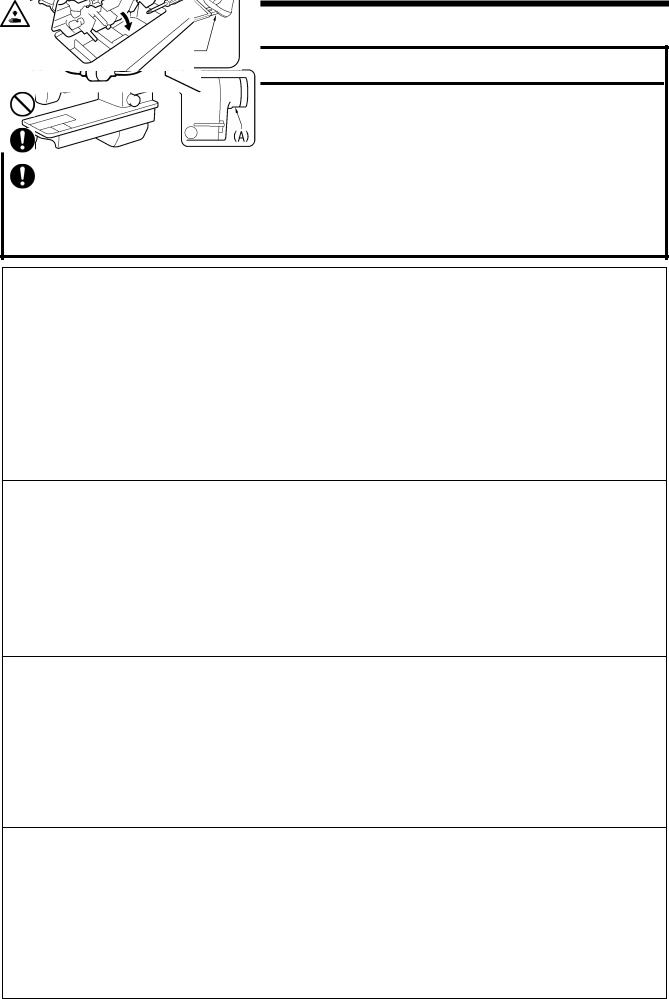
Carrying the machine
The machine should be carried by the arm by two people as shown in the illustration.
*Hold the motor cover (A) by hand also so that the pulley does not rotate.
2169B
Tilting back the machine head
Hold section (B) with your foot so that the table does not move, and then push the arm with both hands to tilt back the machine head.
2871M
Returning the machine head to the upright position
1.Clear away any tools, etc. which may be near the table holes.
2.While holding the face plate with your left hand, gently return the machine head to the upright position with your right hand.
2872M
T-8421C, 8422C, 8452C, 8722C, 8752C |
4 |
3. INSTALLATION
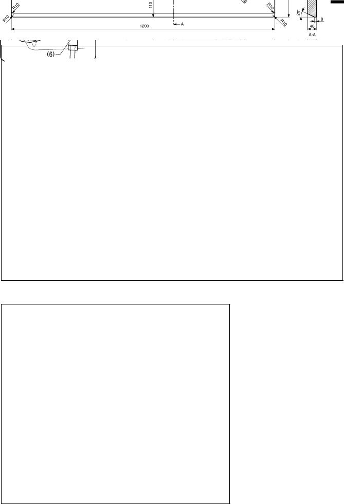
3-1. Table processing diagram
The top of the table should be 40 mm in thickness and should be strong enough to hold the weight and with-stand the vibration of the sewing machine.
Drill holes as indicated in the illustration below.
Cotton stand hole
Cord hole
Head rest hole
Control box mounting hole
2170B
3-2. Installation
1. Control box
(1) Control box
(2) Bolts [3 pcs]
(3) Nuts [3 pcs]
(4) Spring washers [3 pcs]
(5) Washers [3 pcs]
2. Connecting rod
(6) Connecting rod
(7) Nut
4127M
5 |
T-8421C, 8422C, 8452C, 8722C, 8752C |

3. INSTALLATION
3. Oil pan
(1) Head cushions (left) [2 pcs]
(2) Head cushions (right) [2 pcs]
(3) Oil pan
(4) Oiler
2874M
4. Rubber cushions
(1) Rubber cushions [2 pcs]
(2) Nails [4 pcs]
5. Knee lifter complying bar
(3) Knee lifter complying bar
2875M
T-8421C, 8422C, 8452C, 8722C, 8752C |
6 |

3. INSTALLATION
6. Machine head
(1)Hinges [2 pcs]
(2)Machine head
(3)Head rest
NOTE:
Tap the head rest (3) securely into the table hole.
If the head rest (3) is not pushed in as far as it will go, the machine head will not be sufficiently stable when it is tilted back.
2171B
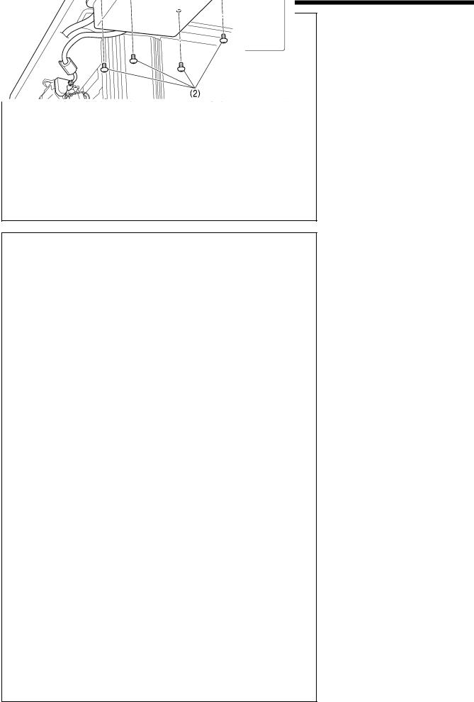
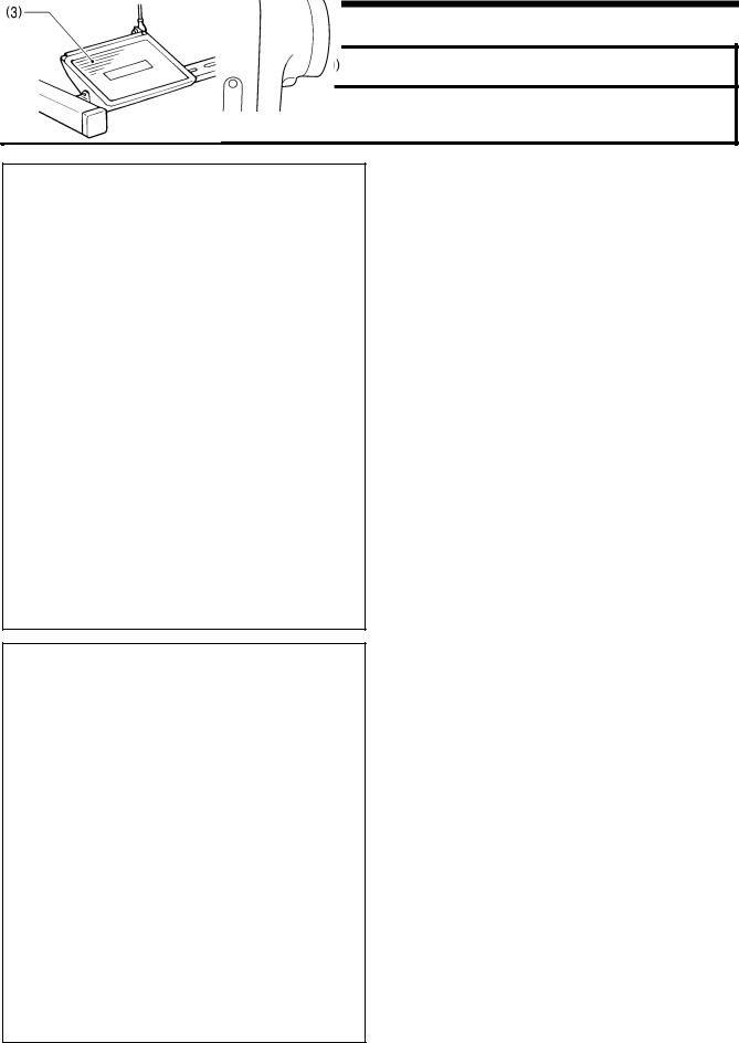
7. Operation panel
(1)Operation panel
(2)Screws [2 pcs]
(Use for tightening rear cover)
2172B
8. Cotton stand
(1) Cotton stand
NOTE:
Securely tighten the nut (4) so that the two rubber cushions (2) and the washer (3) are securely clamped and so that the cotton stand (1) does not move.
2878M
7 |
T-8421C, 8422C, 8452C, 8722C, 8752C |
3. INSTALLATION
9. Knee lifter plate
(1)Knee lifter plate
(2)Bolt
*Loosen the bolt (3) and the bolt (4), and move the knee lifter plate (1) to a position where it is easy to use.
2173B
2880M
2881M
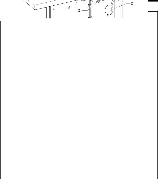
<Knee lifter adjustment>
1.Turn the machine pulley so that the feed dog is below the top of the needle plate.
2.Lower the presser foot (5) by using the lifting lever (4).
3.Loosen the nut (6).
4.Turn the screw (8) to adjust so that the amount of play in the knee lifter (7) is approximately 2 mm when the knee lifter plate (1) is gently pressed.
5.Securely tighten the nut (6).
6.Loosen the nut (9).
7.Turn the screw (10) until the distance between the end of the screw (10) and the knee lifter (7) is approximately 5 mm.
8.Turn the adjusting screw (10) to adjust so that the presser foot (5) is at the desired position within a distance of 13 mm of the needle plate when the knee liter plate (1) is fully pressed.
9.After adjustment is completed, securely tighten the nut
(9).
Within 13 mm
2882M
T-8421C, 8422C, 8452C, 8722C, 8752C |
8 |
3. INSTALLATION
3-3. Lubrication
 CAUTION
Do not connect the power cord until lubrication has been completed, otherwise the machine may operate if the treadle is depressed by mistake, which could result in injury.
Be sure to wear protective goggles and gloves when handling the lubricating oil and grease, so that they do not get into your eyes or onto your skin, otherwise inflammation can result.
Furthermore, do not drink the oil or eat the grease under any circumstances, as they can cause vomiting and diarrhea.
Keep the oil out of the reach of children.
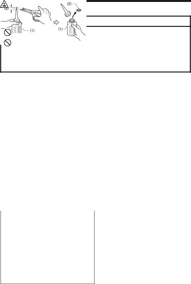
When cutting the nozzle of the oil tank, hold the base of the nozzle securely. If you hold the end of the nozzle, injury from the scissors may result.
|
|
The sewing machine should always be lubricated and the |
|
|
|
oil supply replenished before it is used for the first time, |
|
|
|
and also after long periods of non-use. |
|
|
|
Use only the lubricating oil <NIPPON OIL CORPORATION |
|
|
|
Sewing Lube 10N; VG10> specified by Brother. |
|
|
|
* If this type of lubricating oil is difficult to obtain, the recommended |
|
|
|
oil to use is <Exxon Mobil Essotex SM10; VG10>. |
|
|
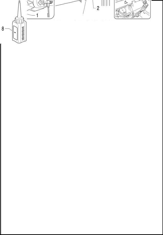
1. |
Hold the base of the nozzle of the accessory oil tank (1), |
|
|
|
and use scissors to cut about half-way along the straight |
|
|
|
section (A) of the nozzle. |
|
2354B |
2. Loosen and remove the nozzle, and then remove the seal (2). |
||
3. |
Tighten the nozzle. |
||
|
|||
|
<Lubricating via the oil cover> |
||
|
|||
|
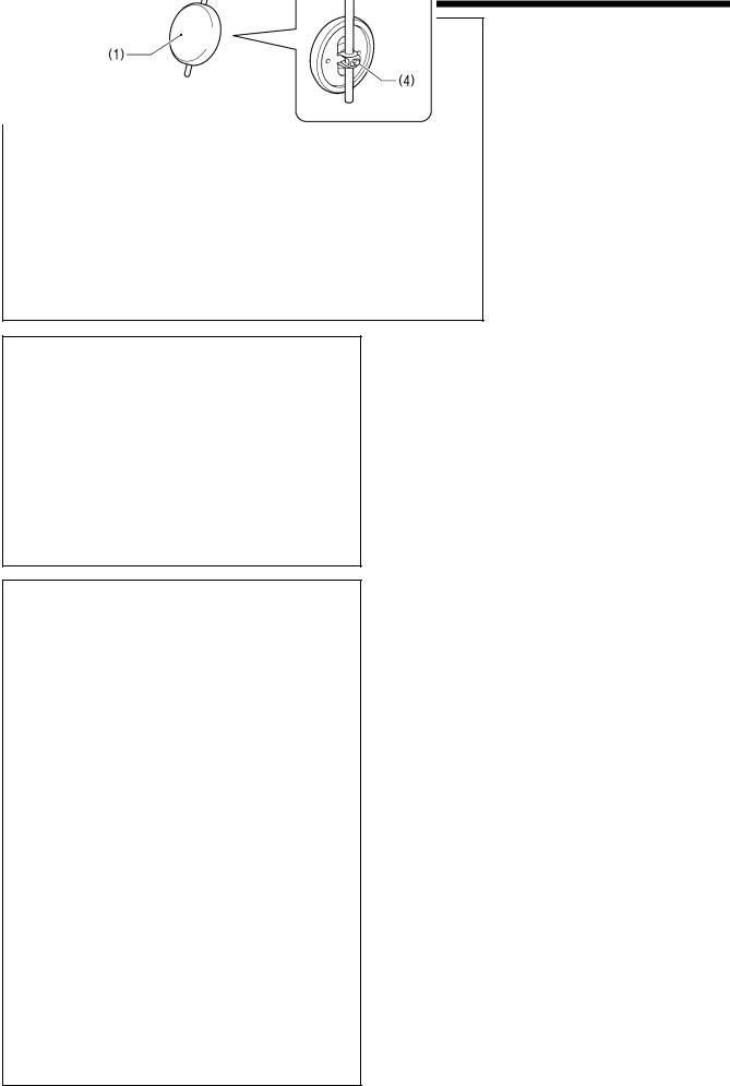
1. |
Tilt back the machine head. |
|
|
2. |
Remove the rubber cap (1). |
|
|
3. |
Use the accessory oil tank (2) to pour lubricating oil into |
|
|
|
the oil cover (3) until the oil level reaches the reference |
|
|
|
line (4). |
|
|
|
NOTE: |
|
|
|
Do not fill with lubricating oil past the reference line (4). |
|
|
|
If you pour in too much lubricating oil, it may spill out |
|
|
|
when the machine head is tilted back. |
|
|
4. |
Replace the rubber cap (1). |
|
|
5. |
Return the machine head to its original position. |
|
|
* If the lubricating oil level drops below the bottom (6) of the |
||
|
|
oil gauge window (5), be sure to add more oil. |
|
2355B |
|
|
|
|
<Lubricating via the oil tank> |
||
|
|||
|
|||
|
1. |
Remove the rubber cap (1). |
|
|
2. |
Use the accessory oil tank (2) to pour in lubricating oil until |
|
|
|
the oil level reaches the top reference line (4) of the oil |
|
|
|
gauge window (3). |
|
|
3. |
Replace the rubber cap (1). |
|
|
* If the lubricating oil level drops below the bottom reference |
||
|
|
line (5), be sure to add more oil. |
|
2356B
9 |
T-8421C, 8422C, 8452C, 8722C, 8752C |

3. INSTALLATION
■Lubrication
Apply 1 - 2 drops of oil to the places indicated by the arrows.
<Minimum lubrication type only>
*Do not apply oil for semi dry types.
<T-8452C, 8752C>
2200B
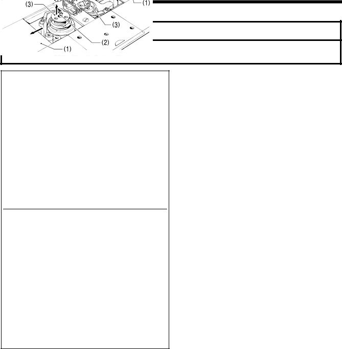
<Semi dry type and minimum lubrication type>
Rotary hook race (left and right)
2174B
2887M
T-8421C, 8422C, 8452C, 8722C, 8752C |
10 |
3. INSTALLATION
3-4. Connecting the cords
 DANGER
Wait at least 5 minutes after turning off the power switch and disconnecting the power cord from the wall outlet before opening the face plate of the control box. Touching areas where high voltages are present can result in severe injury.
 CAUTION
Contact your Brother dealer or a qualified electrician for any electrical work that may need to be done.
Do not connect the power cord until all cords have been connected.
The machine may operate if the treadle is depressed by mistake, which could result in injury.
When securing the cords, do not bend the cords excessively or fasten them too hard with staples, otherwise there is the danger that fire or electric shocks could occur.
Be sure to connect the ground. If the ground connection is not secure, you run a high risk of receiving a serious electric shock, and problems with correct operation may also occur.
3-4-1. Opening the control box cover
(1) Screw
(2) Cover
4137M
3-4-2. Connecting the cords
1. Sewing machine cords
2175B
11 |
T-8421C, 8422C, 8452C, 8722C, 8752C |
3. INSTALLATION
Lower the tab (6). |
Raise the tab (6). |
Push in securely until the tabs (6) engage.
<Removal>
Press the tab.
<Securing>
Cords
<Closing the cover>
4139M
4140M
4141M
(1)6-pin head detector unit connector
(2)12-pin operation panel connector
(3)10-pin resolver connector
(4)14-pin machine connector
(5)4-pin motor connector
2. Binding the cords
(1) Repeat cable tie
NOTE:
Bind the cords in such a way that the connector does not get pulled out. All cords that come out from the control box should be secured to the cord holder (2) using the repeat cable tie (1), otherwise vibration from the sewing machine may cause the cords to become disconnected, which can cause problems with the operation of the control box.
T-8421C, 8422C, 8452C, 8722C, 8752C |
12 |
3. INSTALLATION
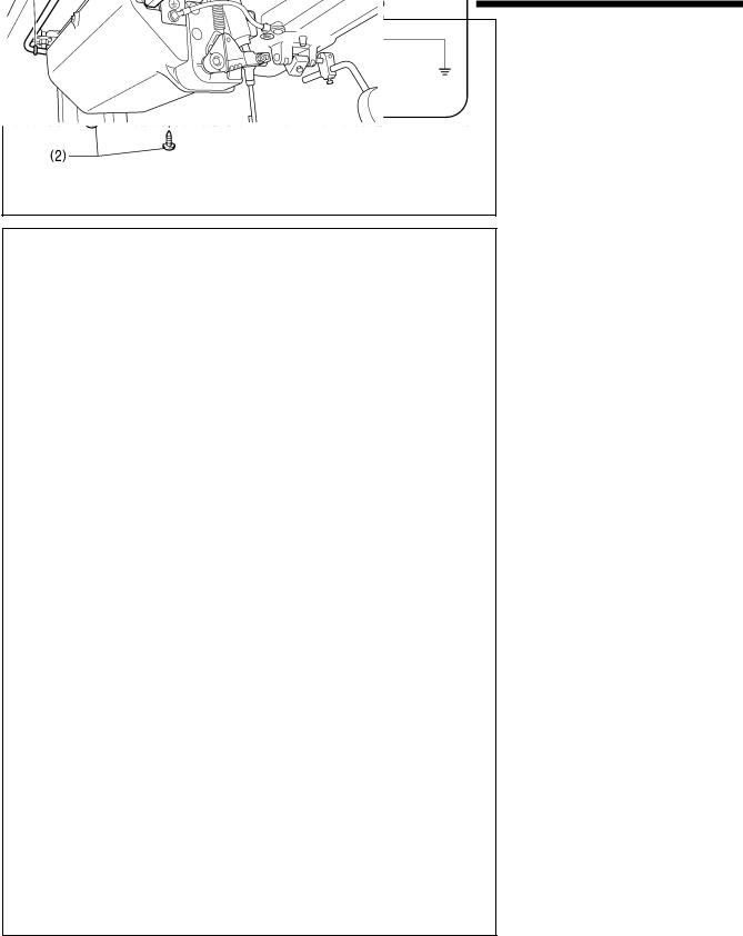
3. Ground wire
(1) Ground wire
(2) Washer
(3) Spring washer
(4) Screw
Oil pan
Ground symbol |
Ground symbol |
2176B
4143M
<Seen from underneath table>
Leg
Control box
Green and yellow wire (ground wire)
4144M
4. Other cords
Connect cords that match the voltage specifications.
< Europe specifications >
(1)Filter box
(2)Screws [4 pcs.]
(3)Staples [7 pcs.]
(4)Power cord
1.Attach an appropriate plug to the power cord (4). (The green and yellow wire is the ground wire.)
2.Insert the power plug into a properly-grounded electrical outlet.
NOTE:
Take care when tapping in the staples (3) to make sure that they do not pierce the cords.
Do not use extension cords, otherwise machine operation problems may result.
13 |
T-8421C, 8422C, 8452C, 8722C, 8752C |
3. INSTALLATION
Operator
4145M
2177B
Green and yellow wire (ground wire)
2178B
<200V system>
(1)Power switch
(2)Screws [2 pcs]
(3)3-pin power supply connector
(4)Power cord
(5)Staples [5 pcs.]
1.Attach an appropriate plug to the power cord (4). (The green and yellow wire is the ground wire.)
2.Insert the power plug into a properly-grounded electrical outlet.
NOTE:
Take care when tapping in the staples (5) to make sure that they do not pierce the cords.
Do not use extension cords, otherwise machine operation problems may result.
T-8421C, 8422C, 8452C, 8722C, 8752C |
14 |
3. INSTALLATION
<100V/400V system>
(1) Power switch
(2) Screws [2 pcs]
Operator
4145M
2179B
Green and yellow wire (ground wire)
2380B
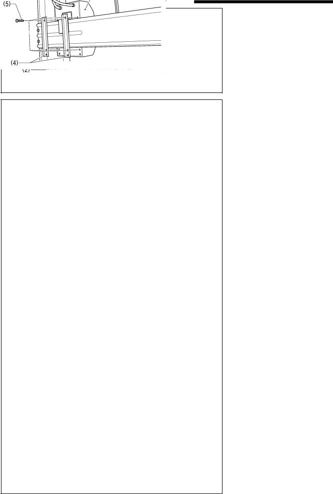
(3)Transformer box
(4)Transformer box plates [2 pcs.]
(5)Screw [with washer]
(6)3-pin power supply connector
(7)Staples [6 pcs.]
(8)Cord clamps [2 pcs.]
(9)Power cord
1.Attach an appropriate plug to the power cord (9). (The green and yellow wire is the ground wire.)
2.Insert the power plug into a properly-grounded electrical outlet.
NOTE:
Take care when tapping in the staples (7) to make sure that they do not pierce the cords.
Do not use extension cords, otherwise machine operation problems may result.
15 |
T-8421C, 8422C, 8452C, 8722C, 8752C |
3. INSTALLATION
3-5. Test operation (Operating the treadle)
 CAUTION
Do not touch any of the moving parts or press any objects against the machine while sewing, as this may result in personal injury or damage to the machine.
2114M
<Turning on the power>
Press the ON power switch (1).
The power indicator (2) will illuminate.
2182B
2207B
2117M
<Test operation>
1.Check that the machine sews at low speed when the treadle (3) is gently pressed to position (B).
NOTE:
If the sewing machine does not operate even when the treadle (3) is depressed, check the position of the safety switch. (Refer to “13-1. Safety switch position”.)
2.Then check that it sews at high speed when the treadle
(3)is gently pressed to position (C).
3.After pressing the treadle (3) forward, check that the needle is lowered to the top of the needle plate when the treadle (3) is returned to the neutral position (A). (when needle down stopping has been set.)
4.If the treadle (3) is pressed to position (D), (thread trimming is carried out for models with thread trimmer) and the needle rises above the needle plate and stops.
5.With the machine head tilted back, depress the treadle (3) and check that the sewing machine does not operate.
NOTE:
If the sewing machine operates when the treadle (3) is depressed while the machine head is tilted back, the safety switch is probably faulty. Contact the place of purchase.
T-8421C, 8422C, 8452C, 8722C, 8752C |
16 |
3. INSTALLATION
3-6. Adjusting the treadle operation
4259M
4260M
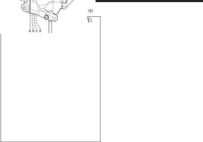
<Forward depression sensitivity adjustment>
If the machine starts running at low speed when your foot is simply resting on the treadle, or if the treadle pressure is felt to be too weak, adjust the position (a to c) at which the treadle spring (1) is hooked onto the treadle lever (2).
*a is the weakest position, and it becomes gradually stronger at b, c and d respectively.
<Backward depression sensitivity adjustment>
1.Loosen the nut (3) and turn the bolt (4).
*When the bolt (4) is tightened, the treadle operation becomes heavier, and when it is loosened, the operation becomes lighter.
2.Tighten the nut (3).
<Adjusting the treadle stroke>
Remove the nut (5), and then move the connecting rod joint
(6) from the position in figure A to the position in figure B. The treadle stroke will then be increased by approximately 27 %.
At this time, the treadle forward and backward depression sensitivity will change, so readjust if necessary.
17 |
T-8421C, 8422C, 8452C, 8722C, 8752C |
4. PREPARATION BEFORE SEWING
4. PREPARATION BEFORE SEWING
4-1. Installing the needle
 CAUTION
Turn off the power switch before installing the needle.
The machine may operate if the treadle is depressed by mistake, which could result in injury.
<T-8421C, 8422C, 8722C>
Long groove
2461B
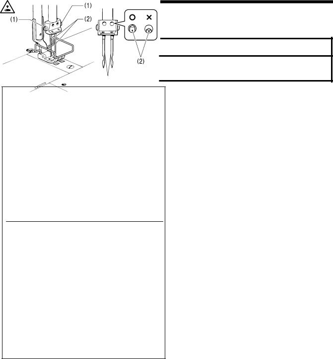
<T-8452C, 8752C>
1.Turn the machine pulley to move the needle bar to its highest position.
2.Loosen the screws (1).
3.Insert the needle (2) straight in as far as it will go so that the long groove is facing inward, and then securely tighten the screws (1).
Long groove
2462B
T-8421C, 8422C, 8452C, 8722C, 8752C |
18 |
4. PREPARATION BEFORE SEWING
4-2. Removing the bobbin
 CAUTION
Turn off the power switch before removing the bobbin.
The machine may operate if the treadle is depressed by mistake, which could result in injury.
<Latch type>
1. Open the slide plates (1) by moving them to the right and left.
2. Pull the rotary hook latches (2) upward, and them remove the bobbins (3).
2463B
<Bobbin case type>
1. Open the slide plates (1) by moving them to the right and left.
2. Lift up the latch (2) of the rotary hook, and then remove the bobbin case (3).
3. Remove the bobbin.
2464B
19 |
T-8421C, 8422C, 8452C, 8722C, 8752C |
4. PREPARATION BEFORE SEWING
4-3. Winding the lower thread
 CAUTION
Do not touch any of the moving parts or press any objects against the machine while winding the lower thread, as this may result in personal injury or damage to the machine.
|
2897M |
1. |
Turn on the power switch. |
|
|
2. |
Place the bobbin (1) onto the bobbin winder shaft (2). |
|
|
3. |
Wind the thread several times around the bobbin (1) in the |
|
|
|
direction indicated by the arrow. |
|
|
|
* Check that the thread is not loose anywhere along the |
|
|
|
thread path. |
|
|
4. |
Push the bobbin presser arm (3) toward the bobbin (1). |
|
|
||
|
|
5. |
Raise the presser foot with the lifting lever. |
|
|
6. |
Depress the treadle. Lower thread winding will then start. |
|
|
7. |
Once winding of the lower thread is completed, the bobbin |
|
|
|
presser arm (3) will return automatically. |
|
|
8. |
After the thread has been wound on, remove the bobbin |
|
|
|
and cut the thread with the knife (4). |
|
|
|
|
|
|
|
|
|
|
|
|
|
|
|
|
|
|
|
|
More thread
Less thread
*Loosen the screw (5) and move the bobbin presser (6) to adjust the amount of thread wound onto the bobbin.
NOTE:
The amount of thread wound onto the bobbin should be a maximum of 80 % of the bobbin capacity.
|
|
|
2123M |
2124M |
|
T-8421C, 8422C, 8452C, 8722C, 8752C |
20 |
Loading...