


Broan QP330BL, QP330WW, QP336BL, QP336SS, QP336WW Installation Guide
...MODELS QP330BL • QP330SS • QP330WW
QP336BL • QP336SS • QP336WW
QP342BL • QP342SS • QP342WW
EVOLUTIONTM 3 |
Page 1 |
QP3 Series Range Hoods |
|
READ AND SAVE THESE INSTRUCTIONS
FOR DOMESTIC COOKING ONLY
WARNING |
|
WARNING |
TO REDUCE THE RISK OF FIRE, ELECTRIC SHOCK, OR INJURY TO PERSONS, OBSERVE THE FOLLOWING:
1.Use this unit only in the manner intended by the manufacturer. If you have questions, contact the manufacturer at the address or telephone number listed in the warranty.
2.Before servicing or cleaning unit, switch power off at service panel and lock the service disconnecting means to prevent power from being switched on accidentally. When the service disconnecting means cannot be locked, securely fasten a prominent warning device, such as a tag, to the service panel.
3.Installation work and electrical wiring must be done by a qualified person(s) in accordance with all applicable codes and standards, including fire-rated construction.
4.Sufficient air is needed for proper combustion and exhausting of gases through the flue (chimney) of fuel burning equipment to prevent backdrafting. Follow the heating equipment manufacturer’s guideline and safety standards such as those published by the National Fire Protection Association (NFPA), and the American Society of Heating, Refrigeration and Air Conditioning Engineers (ASHRAE), and the local code authorities.
5.This product may have sharp edges. Be careful to avoid cuts and abrasions during installation and cleaning.
6.When cutting or drilling into wall or ceiling, do not damage electrical wiring and other hidden utilities.
7.Ducted fans must always be vented to the outdoors.
8.Use only metal ductwork.
9.Do not use this fan with any solid-state speed control device.
10.As an alternative, this product may be installed with the ULapproved cord kit designated for the product, following instructions packed with the cord kit.
11.This unit must be grounded.
TO REDUCE THE RISK OF A RANGE TOP GREASE FIRE:
1.Never leave surface units unattended at high settings. Boilovers cause smoking and greasy spillovers that may ignite. Heat oils slowly on low or medium settings.
2.Always turn hood ON when cooking at high heat or when flambéing food (i.e. Crepes Suzette, Cherries Jubilee, Peppercorn Beef Flambé).
3.Clean ventilating fans frequently. Grease should not be allowed to accumulate on fan or filter.
4.Use proper pan size.Always use cookware appropriate for the size of the surface element.
TO REDUCE THE RISK OF INJURY TO PERSONS IN THE EVENT OF A RANGE TOP GREASE FIRE, OBSERVE THE FOLLOWING:*
1.SMOTHER FLAMES with a close-fitting lid, cookie sheet, or metal tray, then turn off the burner. BE CAREFUL TO PREVENT BURNS. If the flames do not go out immediately, EVACUATE AND CALL THE FIRE DEPARTMENT.
2.NEVER PICK UP A FLAMING PAN — You may be burned or spread the fire.
3.DO NOT USE WATER, including wet dishcloths or towels - a violent steam explosion will result.
4.Use an extinguisher ONLY if:
A.You know you have a Class ABC extinguisher, and you already know how to operate it.
B.The fire is small and contained in the area where it started.
C.The fire department is being called.
D.You can fight the fire with your back to an exit.
* Based on “Kitchen Firesafety Tips” published by NFPA.
CAUTION
1.For indoor use only.
2.For general ventilating use only. Do not use to exhaust hazardous or explosive materials and vapors.
3.To avoid motor bearing damage and noisy and/or unbalanced impeller, keep drywall spray, construction dust, etc., off power unit.
4.Do not use over cooking equipment greater than 60,000 BTU/hr. as the blower motor will shut down intermittantly.
5.Your hood motor has a thermal overload which will automatically shut off the motor if it becomes overheated. The motor will restart when it cools down. If the motor continues to shut off and restart, have the hood serviced.
6.The top of the hood MUST NOT BE LESS than 24” and at a maximum of 30” above cooktop for best capture of cooking impurities.
7.This hood is not intended to be used as a shelf.
8.Please read specification label on product for further information and requirements.
NOTE |
If hood is to be installed non-ducted: |
Purchase a set of (2) non-ducted filters for 30” wide hoods (Model BPPF30) & 36” wide hoods (Model BPPF36) or a set of (3) non-ducted filters for 42” wide hoods (Model BPPF42) from your local distributor or retailer and attach them to the aluminum mesh filters.
Register your product online at: www.broan.com
Installer: Leave this manual with the homeowner.
Homeowner: Cleaning, Maintenance and Operating instructions on page 2.
MODELS QP330BL • QP330SS • QP330WW QP336BL • QP336SS • QP336WW QP342BL • QP342SS • QP342WW
Page 2
CONTENTS
INCLUDED WITH THE HOOD:
|
(1) 3¼” X 10” |
|
DAMPER / DUCT |
|
CONNECTOR |
GREASE |
|
FILTERS |
|
(2 - FOR 30” & 36” HOODS) |
|
3 - FOR 42” HOODS) |
|
(4) |
(1) 7” ROUND |
DUCT |
|
HALOGEN |
CONNECTOR |
BULBS |
|
(1) PARTS BAG CONTAINING:
(3)  WIRE
WIRE  NUTS
NUTS
(9)
#8 X 1/4” DUCT
CONNECTOR
SCREWS

 (1)
(1) 
 BULB
BULB
SUCTION
CUP TOOL
(5) #10 X 5/8” RD. HD. MOUNTING SCREWS
(1) NON-DUCT DIVERTER
(2) #8 X 5/16” MACHINE
SCREWS &
(2)
#8 WASHERS
FOR NON-DUCT
DIVERTER
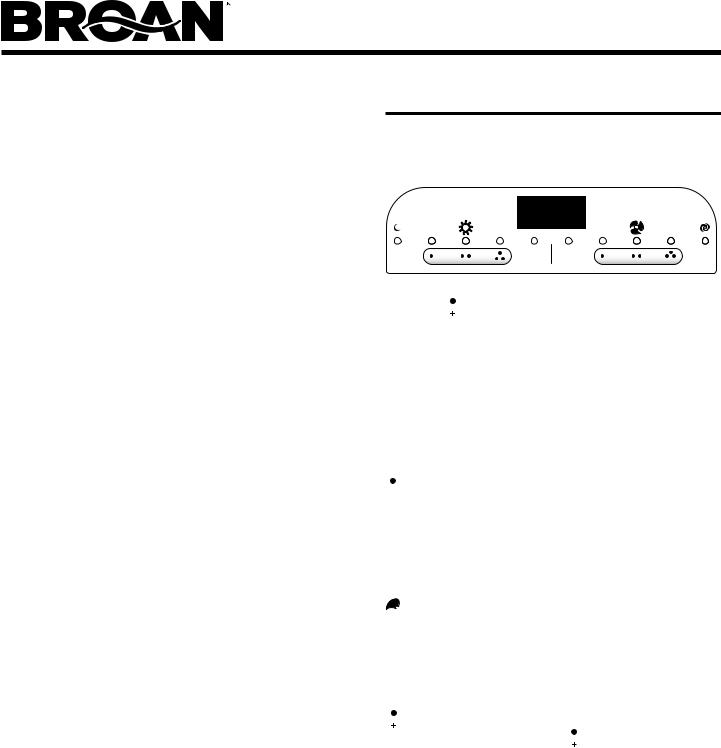
OPERATION
Always turn the hood ON before cooking in order to establish an air flow in the kitchen. After turning off the range, let the hood run for a few minutes to clear the air.
Operate the hood as follows:
NOTE
The  and
and 
 buttons are used to adjust and toggle the menu and timer settings.
 LIGHT (3-Pushbutton Switches 4-light Settings)
 Turns the light on the low setting and activates a green indicator above the button. Pressing the
  button a second time activates the night time setting and illuminates the
  indicator.

 Turns the light on the medium setting and activates a green indicator above the button.

 Turns the light on the high setting and activates a green indicator above the button.
Pressing and holding the same light button again will turn the lights off.
When the night time setting is active, pressing and holding the low light setting button  will turn the night time setting off.
CLEANING & MAINTENANCE
For performance, appearance, and health reasons, clean filter, fan and grease-laden surfaces. Use only a clean cloth and mild detergent solution on stainless and painted surfaces.
Clean all-metal filters in the dishwasher using a non-phosphate detergent. Discoloration of the filter may occur if using phosphate detergents, or as a result of local water conditions - but this will not affect filter performance. This discoloration is not covered by the warranty.
Clean the non-duct recirculating filter surfaces frequently with a damp cloth and a mild detergent. DO NOT immerse filters in water or put in dishwasher. The special “Clean Sense” feature indicates when the filter is to be replaced. The blue and yellow strips will blend to green when it is time to change the filter. The “Clean Sense” feature works best when facing toward the cooking surface. Change the non-duct recirculating filters every 6 months. For replacement non-duct recirculating filters - purchase S99010353 or Model BPPF30 for 30 wide hoods”, S99010354 or Model BPPF36 for 36” wide hoods, or S99010360 or Model BPPF42 for 42” wide hoods.
The motor is permanently lubricated and never needs oiling. If the motor bearings make excessive or unusual noise, replace the motor with the exact service motor. The impeller should also be replaced.
Use 120 V, 50 W, shielded halogen bulbs - MR16 with GU10 base.
 FAN (3-Pushbutton Switches 4-fan speeds)
 Turns the fan on the low speed and activates a green indicator above the button.

 Turns the fan on the medium speed and activates a green indicator above the button.

 Turns the fan on the high speed and activates a green indicator above the button. Pressing the
 button a second time activates the boost fan speed and illuminates the
  indicator.
Pressing and holding the same fan button again will turn the fan off.
When the boost speed is active, pressing and holding the high speed button will turn the boost speed off.
NOTE
This hood utilizes an offset blower design to achieve greater performance and lower sound levels. As a result, you may notice that cooking impurities are more attracted to one side or appear to be pulled-in faster than they appear on the opposite side. This is completely normal. The hood has been designed and tested to provide good capture of cooking impurities and odors under all normal cooking conditions regardless of the cooking location on the cooktop. Please note that cooking on the rear burners will always result in the best capture of cooking impurities, regardless of the hood design.
MODELS QP330BL • QP330SS • QP330WW QP336BL • QP336SS • QP336WW QP342BL • QP342SS • QP342WW
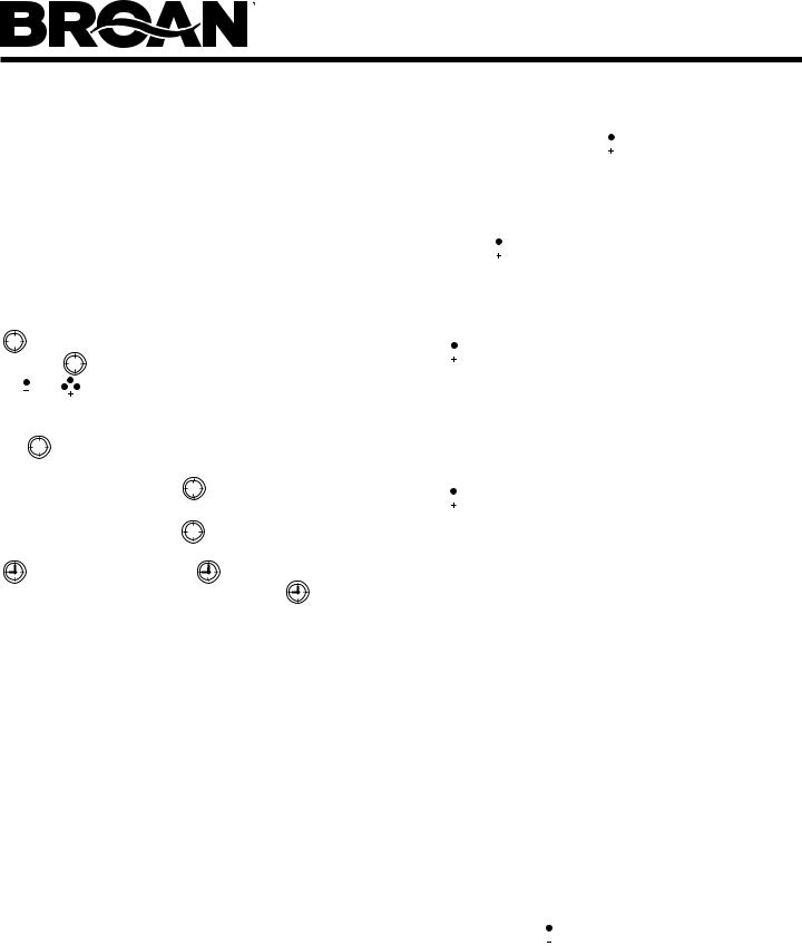
 10-MINUTE DELAY OFF
When your hood fan is on (any speed) press the  button to activate the delay off feature. When activated, the hood fan will automatically turn off after 10-minutes has elapsed. The delay feature is active when the following appear on the LED screen: A green indicator illuminated above the delay
  button, a numeric countdown “10-0”, and a clockwise rotating LED. The delay button can be pressed once again, to stop the delay countdown. Pressing the
  button again will resume the delay countdown. Pressing and holding the button will turn off the feature.
|
|
TIMER |
button to activate the timer setting feature. Use |
||
|
|
||||
Press the |
|
|
|||
|
|
||||
|
|
||||
the and |
buttons to reduce or advance the timer setting to |
||||
the desired duration. When the desired timer setting is reached, allow 3 seconds without pressing any additional button or press
the |
|
button once again. The timer will then activate, and |
|
the countdown will be displayed on the LED screen along with
an green indicator above the |
|
button. After the timer has |
|
reached “0:00”, an audible beep will be heard. The beep will
continue until the timer button |
|
is pressed once again. The |
|
timer countdown can be stopped at any time by pressing the
once again. Pressing the |
button again will resume |
|
the timer countdown. Pressing and holding the |
button will |
|
turn off the feature. Note that when both the timer and delay off features are active together, the timer function will be illuminated on the LED display, and the delay off countdown will be active, but not displayed.
FEATURE MENU
Your hood offers many settings that can be accessed and adjusted by scrolling through the feature menu. Your hood fan must be off to be able to activate and access the feature menu. Pressing the  button when the hood fan is off will activate the feature menu. Pressing the
  button again when the feature menu is active will scroll through the various features that can be adjusted/set. When the feature menu is active, if a button is not pressed within 10 seconds or after scrolling through all menu settings, the feature menu will automatically be exited, and all selected settings will be saved. A green indicator above the
  icon will illuminate when the feature menu is active. The following features can be adjusted sequentially:
Page 3
CLOCK SETTING
Press the  button once, the “hours” will begin blinking in the LED screen. Use the
  and
and 
 buttons to set the appropriate hours for the clock. A small indicator will illuminate in the left corner of the LED screen to designate “pm”. After the hours are set, press the
  button to advance the menu to the minute selection. The minutes will begin blinking in the LED screen. Use the
  and
and 
 buttons to set the minutes. Press the
  button again to advance the menu to select “display” settings.
DISPLAY (default from factory - display ON)
The LED screen will display the display feature -d-. Use the  or
or 
 button to toggle the LED screen on (d on) or off (doFF). When the display off (doFF) feature is selected, the LED display clock illumination is disabled. Press the
  button again to advance the menu to select the “Sleep” setting.
SLEEP MODE (default from factory - OFF)
The LED screen will display the “Sleep” feature -S- . Use the  or
or 
 button to toggle the Sleep feature on (S on) or off (S off). When the Sleep on (S on) feature is selected, the LED screen and fan/light LED indicators are disabled. The ambient light sensor, delay-off and timer features will also be disabled. All controls for the fan and light operation, including Heat Sentry, are still active. Press the
  button again to advance the feature menu to select the “Ambient Light Sensor” setting. Note: To access the feature menu when the Sleep Mode is active, press and hold the
 button for 2 seconds.
AMBIENT LIGHT SENSOR (default from factory - Level 1 ON)
There are two level settings for the ambient light sensor. When either of the two settings is active, the light sensor will detect a low level of light in your kitchen, and will automatically turn the task lights on the hood to the night time setting. The other light settings are still functional. If selected when the ambient light sensor is active, they will temporarily overide the ambient light sensor until they are turned off. The level 1(Aon1) ambient light sensor setting will require your kitchen to be more dark than the level 2 (Aon2) setting before activating the night time setting. The LED screen will display the ambient light sensor function -A-. Use the  or
or 
 button to select the light sensor setting Aon1, Aon2, or AoFF. The Off (AoFF) setting deactivates the automatic ambient light sensor feature so the night time light operation is manual.
Note that the feature menu can be exited any time by not pressing any button(s) for 10 seconds or by scrolling through the entire feature menu.
MODELS QP330BL • QP330SS • QP330WW QP336BL • QP336SS • QP336WW QP342BL • QP342SS • QP342WW
HEAT SENTRY SYSTEM
This range hood is equipped with an advanced Heat Sentry system that monitors excessive temperature and automatically adjusts the fan to the appropriate setting.
1)If the fan is on, the Heat Sentry system will increase the fan setting when the temperature is elevated. If the temperature continues to rise, the Heat Sentry system will continue to increase the fan setting until the temperature is stabilized or reduced. The flashing light above the fan button shows the Heat Sentry system fan setting. Once the temperature has reduced, the Heat Sentry system will change the fan to the original setting.
2)If the fan is off, the Heat Sentry system will automatically turn the fan on to its highest speed when the temperature is above normal. When the Heat Sentry system is on, the light above the high speed fan button will flash on and off. After the temperature has lowered to normal, the fan speed will be reduced until the temperature has stabilized, then the fan will turn off.
Note: Canadian version does not have this function.
FUSES |
|
|
RANGE HOOD CONTROL BOARD |
MAIN |
LIGHT |
FUSE |
FUSE |
The Range Hood Control Board contains a Main Fuse and a
Light Fuse to protect the controls from power surges. If a fuse has opened (blown), the green fan setting or light setting indicators will not operate properly when the fan or light buttons are pressed, and the fan and lights will not turn on.
New fuses can be purchased at your local electronic supply store. Use 8A, 120V, 5 mm diameter, 20 mm long, fast-acting, cartridgetype fuses.
To replace a fuse (by qualified person(s):
1.Disconnect power at service entrance.
2.Remove filters and bottom pan.
3.Remove and inspect fuse. If it is not open (blown), additional diagnostics are needed.
Page 4
MAKE-UP AIR DAMPER
The hood is compatible with Broan Make-Up Air Damper Model MD6T or Model MD8T (optional). Purchase separately.
Make the connection to the Make-Up Air Damper with low voltage wiring, as shown. See Make-Up Air Damper instructions for additional information.
BACK OF HOOD |
|
LOW-VOLTAGE CONNECTOR |
|
FOR MAKE-UP AIR DAMPER |
|
RANGE |
MAKE-UP AIR |
HOOD |
DAMPER |
LOW-VOLTAGE
WIRES
120 |
24 |
VAC |
VAC |
DAMPER
MOTOR
REMOTE CONTROL
The hood is compatible with Broan RF Remote Control Model BCR1 (optional). Purchase separately.
PREPARE HOOD LOCATION
ROOF CAP |
3¼" X 10" or |
|
7" ROUND DUCT |
|
(For vertical |
|
discharge) |
|
SOFFIT |
|
|
|
HOUSE WIRING |
|
CABINET |
(Top or Back of hood) |
|
|
WALL CAP |
|
HOOD |
|
|
24" - 30" ABOVE |
3¼" X 10" DUCT |
|
COOKING SURFACE |
|
|
(For horizontal discharge) |
|
|
|
|
1 |
Determine whether hood will discharge vertically (3¼” |
|
|
x 10” or 7” Round), or horizontally (3¼” x 10” only). For |
|
|
vertical or horizontal discharge, run ductwork between |
|
|
the hood location and a roof cap or wall cap. For best |
|
|
results, use a minimum number of transitions and elbows. |
|
MODELS QP330BL • QP330SS • QP330WW QP336BL • QP336SS • QP336WW QP342BL • QP342SS • QP342WW
Page 5
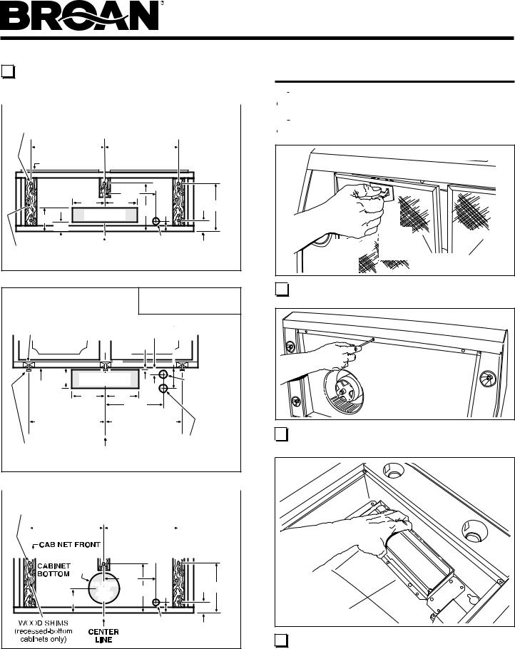
2 |
Use the proper diagram below, for placement of ductwork |
|
and electrical cutout in cabinet or wall. For a non-ducted |
|
installation, DO NOT cut a duct access hole. |
|
|
|
|
|
|
|
|
|
3¼” X 10” |
||
HOOD MOUNTING SCREWS (5) |
VERTICAL DUCTING |
||||||||||
|
|
|
|||||||||
11 |
5/8" (30" hood) |
11 |
5/8" (30" hood) |
||||||||
|
|
14 |
5/8" (36" hood) |
|
|
|
14 |
5/8" (36" hood) |
|
|
|
|
|
|
|
||||||||
17 |
5/8" (42" hood) |
17 |
5/8" (42" hood) |
||||||||
|
|
CABINET FRONT |
|
|
|
|
|
|
|||
|
CABINET |
* 67/8" |
|
|
|
|
BOTTOM |
|
|
|
|
|
5¼" |
5¼" |
11" |
21/8" |
107/8" |
4½" |
VERTICAL DUCT |
|
|||
ACCESS HOLE |
|
|
|
||
¾" |
|
|
|
25/8" |
|
|
|
|
|
|
ELECTRICAL |
|
WOOD SHIMS |
CENTER |
ACCESS HOLE |
||||
(recessed-bottom |
(in cabinet bottom) |
|||||
LINE |
||||||
cabinets only) |
|
|||||
|
|
|
|
|||
|
|
|
|
|
|
3¼” X 10” |
WOOD SHIMS |
|
|
HORIZONTAL DUCTING |
|||
|
|
|
35/8" |
|||
(recessed-bottom |
|
|
|
|||
cabinets only) |
CABINET FRONT |
13/8" |
||||
|
|
|
|
|
3/8" |
|
|
|
4" |
|
* |
|
|
|
|
HORIZONTAL DUCT |
ELECTRICAL |
|||
CABINET |
ACCESS HOLE |
|
||||
|
|
|
|
ACCESS |
||
BOTTOM |
|
5¼" |
5¼" |
|||
|
HOLE |
|||||
|
|
|
|
|
67/8" |
(in wall) |
11 |
5/8" (30" hood) |
11 |
5/8" (30" hood) |
|||
14 |
5/8" (36" hood) |
14 |
5/8" (36" hood) |
|||
17 |
5/8" (42" hood) |
17 |
5/8" (42" hood) |
|||
HOOD |
|
CENTER |
|
MAKE-UP AIR |
||
MOUNTING |
|
|
DAMPER ELECTRICAL |
|||
SCREWS (5) |
|
LINE |
|
CONNECTION HOLE |
||
|
|
|
|
|
|
(in wall) |
|
|
|
|
|
|
|
|
|
|
|
|
|
|
|
|
|
|
|
|
|
7-IN. ROUND |
|||
HOOD MOUNTING SCREWS (5) |
|
|
DUCTING |
|||||||||||||||||||||
11 |
5/8" (30" hood) |
11 |
5/8" (30" hood) |
|
|
|
|
|
||||||||||||||||
|
|
|
|
|
||||||||||||||||||||
|
|
|
|
|
|
14 |
5/8" (36" hood) |
|
|
|
|
|
|
|
14 |
5/8" (36" hood) |
|
|
|
|
|
|
|
|
|
|
|
|
|
|
|
|
|||||||||||||||||
|
|
|
|
|
|
|
|
|
|
|
|
|
|
|
|
|
||||||||
|
|
|
|
17 |
5/8" (42" hood) |
17 |
5/8" (42" hood) |
|
|
|
|
|||||||||||||
|
|
|
|
|
|
|
|
|
|
|
|
|
|
|
|
|
|
|
|
|
|
|
|
|
|
|
|
|
|
|
|
|
|
|
|
|
|
|
|
|
|
|
|
|
|
|
|
|
|
|
|
|
|
|
|
|
|
|
|
|
|
|
|
|
|
|
|
|
|
|
|
|
|
|
|
|
|
|
|
|
|
|
|
|
|
|
|
|
|
|
|
|
|
|
|
|
|
|
|
8" DIA. |
* |
|
|
|
HOLE |
67/8" |
|
|
|
7-IN.ROUND |
|
|
107/8" |
|
|
DUCT |
11" |
21/8" |
|
45/8" |
ACCESS |
|
||
HOLE |
|
|
25/8" |
|
|
|
|
|
|
ELECTRICAL
ACCESS HOLE (in cabinet bottom)
*Note the extra wood shim and mounting screw near the cabinet front, on the cabinet center line.
PREPARE THE HOOD
3 |
Remove parts bag from inside the hardware box included |
|
with the hood. |
|
|
|
|
4 |
Remove all protective polyfilm from the hood (stainless |
|
steel hoods only). |
|
|
|
<![if ! IE]> <![endif]>ç |
|
|
|
(1) |
|
(2) |
ç |
PULL |
|
DOWN |
|||
|
|||
LIFT |
ALUMINUM |
||
OUT |
|||
FILTERS |
|||
|
|
||
5 
 Remove the Aluminum Filters from the hood.
6 Remove 6 Screws holding Bottom Pan to hood. Set bot-  tom pan and screws aside.
DAMPER / |
DUCT CONNECTOR |
7 Remove 2 Screws holding Damper / Duct Connector to hood. Remove damper/duct connector from inside the hood.
FOR DUCTED INSTALLATIONS - Skip to Step 12.

MODELS QP330BL • QP330SS • QP330WW QP336BL • QP336SS • QP336WW QP342BL • QP342SS • QP342WW
Page 6
NON-DUCT
DIVERTER
8 NON-DUCTED INSTALLATION ONLY:
From parts bag: Attach Non-Duct Diverter to Air Box with 2 Screws and 2 Washers.
SCREWS
 NON-DUCT
PLATE
|
NON-DUCT |
|
PLATE |
SLOT |
ç |
|
|
|
NON-DUCT |
|
PLENUM |
9 NON-DUCTED INSTALLATION ONLY:
Remove 2 Screws holding Non-Duct Plate to Non-Duct Plenum and remove plate.
SCREWS |
NON-DUCT |
PLATE |
10 NON-DUCTED INSTALLATION ONLY:
Insert short end of Non-Duct Plate into Non-Duct Plenum Slot. Attach with 2 Screws removed in Step 9.
11 NON-DUCTED INSTALLATION ONLY:
Purchase a set of (2) non-ducted filters for 30” wide hoods (Model BPPF30) & 36” wide hoods (Model BPPF36) or
a set of (3) non-ducted filters for 42” wide hoods (Model BPPF42) from your local distributor or retailer. Attach the non-ducted filters to the aluminum mesh filters following instructions packed with the non-ducted filters.
FOR NON-DUCTED INSTALLATIONS - Skip to “INSTALL THE HOOD”.
7” ROUND
KNOCKOUT
PLATE (also remove 3¼” x 10”  vertical plate)
|
3¼” X 10” |
|
VERTICAL |
|
KNOCKOUT |
3¼” X 10” |
PLATE |
HORIZONTAL |
|
KNOCKOUT |
|
PLATE |
|
12 |
DUCTED INSTALLATION ONLY: |
|
Remove 3¼” x 10 vertical, 3¼” x 10” horizontal, or 7-inch |
round knockout plate(s) as appropriate for your ducting
method. |
|
|
3¼” X 10” |
TOP/BACK |
DAMPER / DUCT CONNECTOR |
|
|
EDGE OF |
DAMPER |
HOOD |
|
|
FLAP |
|
PIVOT |
|
7” ROUND |
|
DUCT |
|
PLATE |
13 |
DUCTED INSTALLATION ONLY: |
|
Attach 3¼” x 10” Damper/Duct Connector (if using 3¼” |
|
x 10” duct) or 7” Round Duct Plate (if using 7-inch round |
duct) over the knockout opening.
Notes:
To accomodate off-center ductwork, the 3¼” x 10” damper/ duct connector can be installed up to ½” on either side
of the hood center and the 7” round duct plate can be installed up to ½” on either side of the hood center.
Install the 3¼” x 10” Damper/Duct Connector with the
Damper Flap Pivot nearest the Top/Back Edge of Hood.
|
MODELS QP330BL • QP330SS • QP330WW |
|
|
|
QP336BL • QP336SS • QP336WW |
|
|
QP342BL • QP342SS • QP342WW |
|
|
|
|
|
|
|
|
Page 7 |
INSTALL THE HOOD |
|
CONNECT THE WIRING |
WARNING
To reduce the risk of electrical shock, switch power off 
 at service panel. Lock or tag service panel to prevent
power from being switched on accidentally.
ELECTRICAL |
WIRING BOX |
COVER |
ELECTRICAL |
POWER |
CABLE |
KNOCKOUT |
14 Remove Electrical Wiring Box Cover from inside  of hood and appropriate Electrical Power Cable
Knockout from top or back of hood.
HOUSE |
POWER CABLE |
15 |
Run House Power Cable between service panel and hood |
|
location. Attach power cable to hood using appropriate clamp. |
16 |
Hang hood from (4) mounting screws driven part-way into |
|
cabinet locations (shown in illustrations under “PREPARE |
|
HOOD LOCATION”). Mounting screws are included in parts |
|
bag. Slide hood back towards wall until mounting screw |
|
heads are engaged in narrow end of keyhole slots in top of |
|
hood. Tighten screws securely. Add 5th mounting screw in |
|
center hole in hood and tighten securely. |
17 |
DUCTED INSTALLATION ONLY: |
|
Connect ductwork to hood and use duct tape to make joints |
|
secure and air-tight. Make sure the damper / duct connector |
|
enters the ductwork and that the damper opens and closes |
|
freely. |
GROUND
SCREW 

HOUSE
POWER CABLE
18 Connect House Power Cable to range hood wiring -  BLACK to BLACK, WHITE to WHITE, and GREEN or
BARE WIRE to Ground Screw. Replace electrical wiring box cover.
19 
 Re-attach Bottom Pan with 6 Screws removed in Step 6.
INSTALL LIGHT BULBS
|
SUCTION |
|
CUP TOOL |
HALOGEN |
(1) |
PUSH IN |
|
BULB |
|
(2) |
|
ROTATE |
|
CLOCKWISE |
|
LIGHT PANEL |
|
SCREWS |
LIGHT PANEL |
|
CAUTION: Bulbs may be hot. Refer to bulb packaging for further information.
20 Install (4) Halogen Bulbs (included with hood). Use 120  V, 50 W, shielded halogen bulbs - MR16 with GU10 base.
NOTE: Suction Cup Tool (included with hood) can be used to install and remove light bulbs.
Align pins on bulb with large diameter opening on socket, then push bulb in towards hood and rotate clockwise until firmly seated.
The position of the bulb socket (depth) is adjustable and may require adjustment when:
a)certain brands of bulbs are difficult to install.
b)the bulb protrudes too far below the light panel.
MODELS QP330BL • QP330SS • QP330WW QP336BL • QP336SS • QP336WW QP342BL • QP342SS • QP342WW
Page 8
LAMP SOCKET
BRACKET
LIGHT |
SCREWS |
PANEL |
To change the depth of bulb sockets:
-Remove bottom pan (See Step 6).
-Remove 2 Light Panel Screws and Light Panel. Set
screws aside.
-Loosen 2 Screws holding Lamp Socket Bracket to Light Panel.
-Adjust socket/bracket to desired depth.
-Re-tighten screws securely.
-Re-attach light panel and bottom pan.
SERVICE PARTS
|
|
15 |
|
12 |
1 |
|
14 |
|
|
|
|
11 |
|
16 |
|
10 |
|
|
3 |
|
|
2 |
|
|
|
|
|
9 |
|
|
|
|
|
|
17 |
|
|
4 |
|
|
|
18 |
5 |
|
|
13 |
|
|
8 |
|
|
|
|
6 |
21 |
DUCTED INSTALLATION ONLY: |
7 |
|
Re-install aluminum filters removed in Step 5. |
|
NON-DUCTED INSTALLATION ONLY:
Install aluminum filters and non-ducted filters - purchased and assembled in Step 11.
WARRANTY
One Year Limited Warranty
Broan-NuTone warrants to the original consumer purchaser of its products that such products will be free from defects in materials or workmanship for a period of one
(1) year from the date of original purchase. THERE ARE NO OTHER WARRANTIES, EXPRESS OR IMPLIED, INCLUDING, BUT NOT LIMITED TO, IMPLIED WARRANTIES OF MERCHANTABILITY OR FITNESS FOR A PARTICULAR PURPOSE.
During this one year period, Broan-NuTone will, at its option, repair or replace, without charge, any product or part which is found to be defective under normal use and service. THIS WARRANTY DOES NOT EXTEND TO FLUORESCENT LAMP STARTERS, TUBES, HALOGEN AND INCANDESCENT BULBS, FUSES, FILTERS, DUCTS, ROOF CAPS, WALL CAPS AND OTHER ACCESSORIES FOR DUCTING. This warranty does not cover (a) normal maintenance and service or (b) any products or parts which have been subject to misuse, negligence, accident, improper maintenance or repair (other than by Broan-NuTone), faulty installation or installation contrary to recommended installation instructions.
The duration of any implied warranty is limited to the one year period as specified for the express warranty. Some states do not allow limitation on how long an implied warranty lasts, so the above limitation may not apply to you.
BROAN-NUTONE’S OBLIGATION TO REPAIR OR REPLACE, AT BROAN-NUTONE’S OPTION, SHALL BE THE PURCHASER’S SOLE AND EXCLUSIVE REMEDY UNDER THIS WARRANTY. BROAN-NUTONE SHALL NOT BE LIABLE FOR INCIDENTAL, CONSEQUENTIAL OR SPECIAL DAMAGES ARISING OUT OF OR IN CONNECTION WITH PRODUCT USE OR PERFORMANCE. Some states do not allow the exclusion or limitation of incidental or consequential damages, so the above limitation or exclusion may not apply to you. This warranty gives you specific legal rights, and you may also have other rights, which vary from state to state. This warranty supersedes all prior warranties.
To qualify for warranty service, you must (a) notify Broan-NuTone at the address or telephone number below, (b) give the model number and part identification and (c) describe the nature of any defect in the product or part. At the time of requesting warranty service, you must present evidence of the original purchase date.
Broan-NuTone LLC, 926 W. State Street, Hartford, Wisconsin 53027 www.broan.com 800-558-1711
Broan-NuTone Canada, Inc., 1140 Tristar Drive, Mississauga, Ontario Canada L5T 1H9 www.broan.ca 877-896-1119 Rev. 08/2007
KEY NO. |
PART NO. |
DESCRIPTION |
1 |
97017727 |
7” Round Duct Plate (includes mounting hardware) |
2 |
97018256 |
User Interface Assembly White (includes interface, |
|
|
nameplate, mounting hardware) |
|
97018257 |
User Interface Assembly Black (includes interface, |
|
|
nameplate, mounting hardware) |
3 |
99528258 |
Nameplate, White |
|
99528259 |
Nameplate, Black |
4 |
97018251 |
Capacitor Kit (includes wire nuts, mounting screw) |
5 |
97018225 |
Light Panel RH White (includes mounting hardware) |
|
97018226 |
Light Panel RH Black (includes mounting hardware) |
|
97018227 |
Light Panel RH Stainless (includes mounting hardware) |
6 |
97018205 |
Filter Kit for 30” (2 per bag) |
|
97018206 |
Filter Kit for 36” (2 per bag) |
|
97018207 |
Filter Kit for 42” (3 per bag) |
7 |
97018220 |
Blower Wheel (includes mounting nut) |
8 |
97018223 |
Motor Kit (includes motor, isolators, mounting hardware) |
9 |
97017728 |
Damper / Duct Connector (includes mounting hardware) |
10 |
97018229 |
Light Panel LH White (includes mounting hardware) |
|
97018230 |
Light Panel LH Black (includes mounting hardware) |
|
97018231 |
Light Panel LH Stainless (includes mounting hardware) |
11 |
97017731 |
Lamp Socket (includes lamp socket, wire nuts, mounting screws) |
12 |
97018233 |
Lamp Socket Bracket |
13 |
97018239 |
Bottom Pan 30” (includes mounting hardware) |
|
97018240 |
Bottom Pan 36” (includes mounting hardware) |
|
97018241 |
Bottom Pan 42” (includes mounting hardware) |
14 |
97018242 |
Non-duct Plenum (includes gasket & mounting hardware) |
15 |
97018243 |
Non-duct Diverter (includes mounting hardware) |
16 |
97018244 |
Non-duct Plate (includes mounting hardware) |
17 |
97018260 |
Circuit Board |
18 |
97018262 |
Transformer (includes mounting hardware) |
Not Shown |
97018224 |
Parts Bag |
Not Shown |
99010353 |
Non-Duct Filter Kit for 30” (2 charcoal filters and 8 filter clips) |
|
99010354 |
Non-Duct Filter Kit for 36” (2 charcoal filters and 8 filter clips) |
|
99010360 |
Non-Duct Filter Kit for 42” (3 charcoal filters and 12 filter clips) |
Not Shown |
99526707 |
Suction Cup Tool |
Not Shown |
97018252 |
Heat Sensor |
Not Shown |
97018253 |
Fuse |
Not Shown |
97018261 |
Ribbon Cable Kit (contains 3) |
Not Shown |
V05921 |
50W Halogen GU10 Bulb |
Order replacement parts by PART NO. - not by KEY NO.
99527291E
 Loading...