


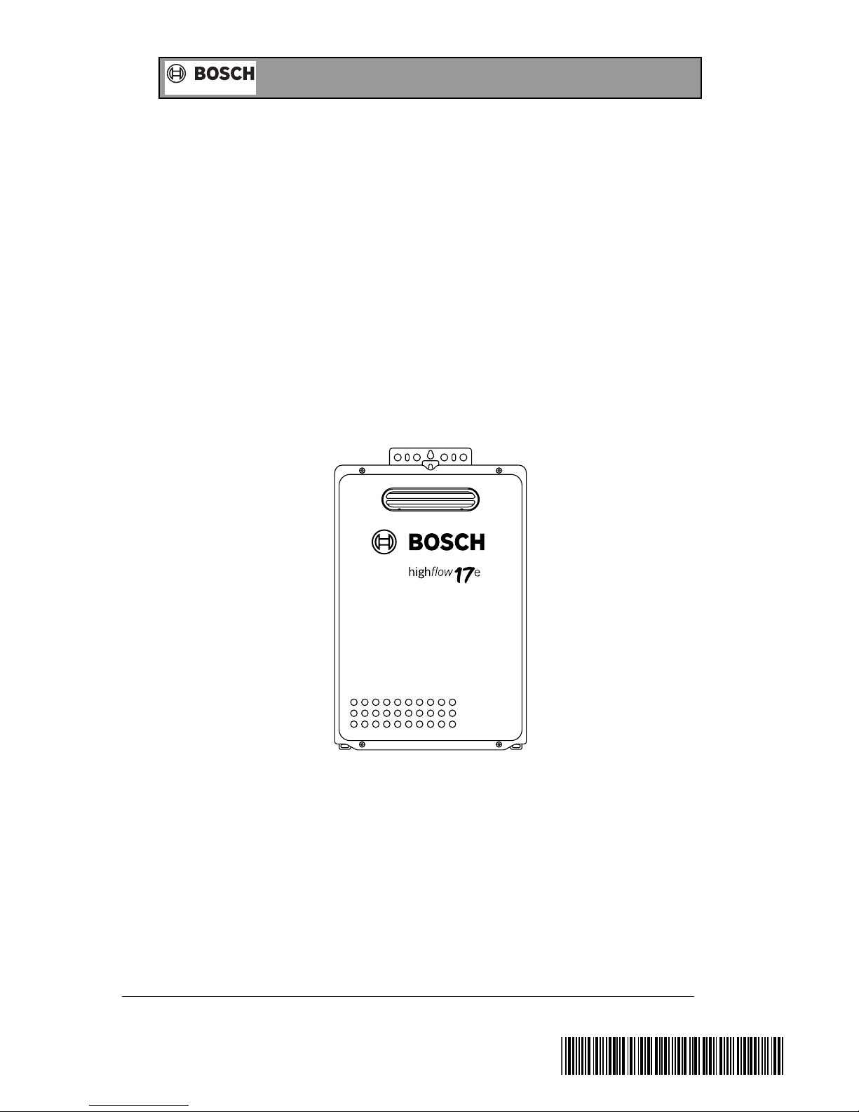
highflow 17e
1
Installation/Operating Instructions
Invented for life
MODELS
Bosch 17e
Bosch 21e
Bosch 26e
(YS1770RA, YS2170RA & YS2670RA)
INSTALLATION MANUAL
This appliance must be installed in accordance with the manufacturer’s installation instructions, AS5601,
AS/NZS3500.4, AS3000 wiring regulations and all Local Building, Water and Gas fitting regulations.
To be installed and serviced only by an authorised person
This appliance is not suitable for use as a pool heater
The “authorised installing person” is responsible for :
1. Correct commissioning of this appliance.
2. Ensure unit performs to the specifications stated on the rating label.
3. Demonstrate operation of unit to customer before leaving.
4. Hand these instructions to customer.
Failure to install this appliance in accordance with these installation instructions may void warranty
SAR
8512-1
*SAR8512C*

2
Page Number
Introduction 3
Dimensions 4
Technical Data 5
Appliance Location 6
Component Details 7
Gas Connection 9
Cold Water Connection 9
Hot Water Connection 10
Electrical Connection 10
Pre-Set Temperature 10
Temperature Selector Pad Installation 11
Temperature Selector Pad Wiring 11
Temperature Control Operation 12
Commissioning and Testing 12
Temperature Setting 13
USER SAFETY INSTRUCTIONS 15
In Case Of Difficulties 15
Warranty Details 16
INDEX
Installation/Operating Instructions
Invented for life

3
This Bosch water heater is an external, electronically controlled gas water heater.
This Bosch appliance is supplied set to operate without temperature selector pads at
a constant 55°C outlet temperature. To set the appliance to a different temperature,
refer to page 13 for details.
Available as optional extras are Main, Bathroom or Sub temperature selector pads.
Only one Main controller and one Bathroom controller can be
connected to the appliance along with up to 2 x Sub-controllers.
The bathroom and sub temperature selector pads have a maximum temperature
setting of 50°C for safety. To ensure compliance with Australian Standard AS/NZS
3500.4, in the bathroom area, this may be achieved by using a Bosch appliance
limited to 50°C or using a Bosch appliance with a delivery temperature greater than
50°C and installed with a tempering valve (high performance). In New Zealand,
please refer to the New Zealand Building Code and all other applicable electrical,
gas fitting and plumbing codes.
Before installing this appliance, carefully check that all packing materials have been
removed and that the appliance is correct for the gas supply to which it is to be
connected
Installation/Operating Instructions
Invented for life
4
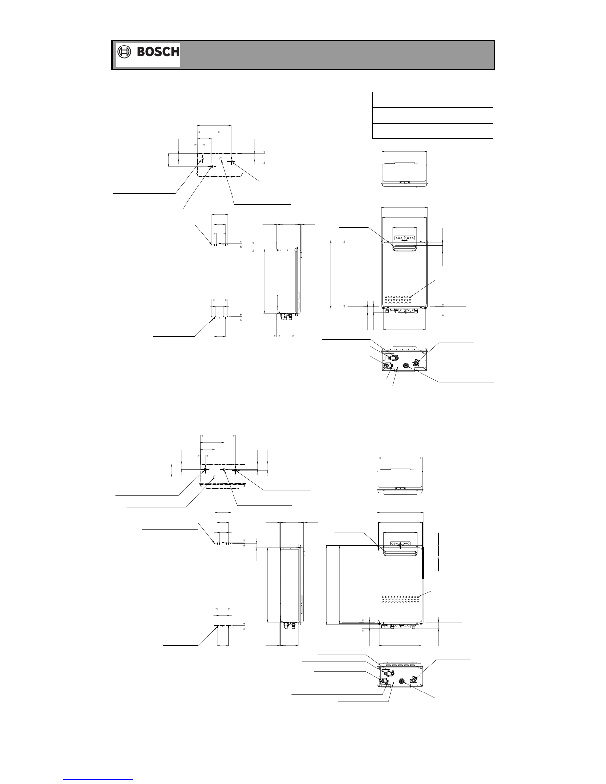
DIMENSIONS YS1770RA, YS2170RA
Installation/Operating Instructions
Invented for life
510〜512
48
44
520
487
542
10
10
120
60
84
133
97
40
37
109
40
57
31
1085
120
10
50
11170
178
255
308〜320
49
338
350
334
2542
L
Powercableintakinghole
Powercableintakinghole
(PSflameinstallationpich)
(Perspectivedrawingfromupperofappliance)
(PSflameinstallationpich)
Bottomofcase
Outlet-waterconnectionR3/4
Inlet-waterconnectionR3/4
GasconnectionR3/4
7-φ7.2hole
Installationholeofwall
(Installedwiththreeholes)
7-φ7.2hole
Installationholeofwall
(Installedwithtwoholes)
Gasconnection
Inlet-waterconnection
Waterdrainvalve(Waterfilter)
Outlet-waterconnection
PressurerelifevalveandWaterdrainvalve
Earthconnectionscrew
Bottomofcase
Air-inlet
Flueterminal
DIMENSIONS YS2670RA
590〜592
567
622
600
120
60
84
44
48
10
10
133
49
318〜320
268
10
50
120
40
97
40
109
85
178
37
338
47
10 11170
31
350
334
253
42 25
Powercableintakinghole
Powercableintakinghole
(PSflameinstallationpich)
(PSflameinstallationpich)
(Perspectivedrawingfromupperofappliance)
Air-inlet
(Installedwithtwoholes)
7-φ7.2hole
Installationholeofwall
PressurerelifevalveandWaterdrainvalve
Earthconnectionscrew
Inlet-waterconnection
Waterdrainvalve(Waterfilter)
Outlet-waterconnection
Bottomofcase
Gasconnection
Bottomofcase
7-φ7.2hole
Installationholeofwall
(Installedwiththreeholes)
Outlet-waterconnectionR3/4
Inlet-waterconnectionR3/4
Flueterminal
GasconnectionR3/4
YS1770RA
YS2170RA
178
214
L
5
Installation/Operating Instructions
Invented for life
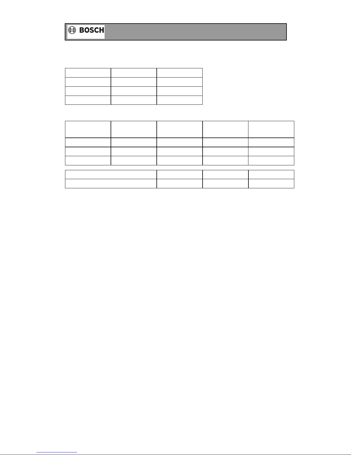
TECHNICAL DATA
Nominal hourly gas consumption by proportional gas control:
17e
21e
26e
135 Mj/hr
170 Mj/hr
200 Mj/hr
135 Mj/hr
170 Mj/hr
200 Mj/hr
Natural Gas LP Gas
Test Point Pressure:
Maximum Inlet Water Pressure 1000 kPa
Input voltage single phase 50Hz AC240/230 Volt
Maximum output current 1 Amp
AGA Approval certificate number 7032
Inlet gas connection male thread 20mm
Cold water connection male thread 20mm
Hot water connection male thread 20mm
Relief valve pressure setting 1600 kPa
DATA PLATE
Fitted inside of cabinet
GAS TYPE
The gas type is nominated on a temporary label located on the front cover, and on the data
plate located inside of cabinet. The gas type is the gas on which this appliance is designed to
operate.
DO NOT OPERATE WITH ANY OTHER GAS TYPE.
WARNING LABELS
Located on the right side of the cabinet- PLEASE READ THESE LABELS CAREFULLY!
YS1770RA
YS2170RA
YS2670RA
.67
.69
.72
.26
.21
.19
Natural Gas
Max (kPa)
Model
Natural Gas
Min (kPa)
.78
.91
.80
LP Gas
Max (kPa)
.23
.23
.22
LP Gas
Min (kPa)
Water heating capacity
Litres a minute raised 25°C
17e
17
21e
21
26e
26
 Loading...