


3100
Table of contents
 Loading...
AutoView
®
Installer/User Guide
3100/3200
USA Notification
Warning: Changes or modifications to this unit not expressly approved by the party responsible for compliance
could void the user’s authority to operate the equipment.
Note: This equipment has been tested and found to comply with the limits for a Class A digital device, pursuant
to Part 15 of the FCC Rules. These limits are designed to provide reasonable protection against harmful
interference when the equipment is operated in a commercial environment. This equipment generates, uses and
can radiate radio frequency energy and, if not installed and used in accordance with the instruction manual, may
cause harmful interference to radio communications. Operation of this equipment in a residential area is likely to
cause harmful interference in which case the user will be required to correct the interference at his own expense.
Canadian Notification
This Class A digital apparatus complies with Canadian ICES-003.
Cet appareil numérique de la classe A est conforme à la norme NMB-003 du Canada.
Japanese Notification
Korean Notification
Safety and EMC Approvals and Markings
UL, FCC, cUL, ICES-003, CE, GS, VCCI, MIC, C-Tick, GOST

AutoView® 3100/3200 Switch
Installer/User Guide
Avocent, the Avocent logo, The Power of Being There, Dambrackas
Video Compression, AutoView and OSCAR are registered trademarks of
Avocent Corporation or its affiliates. All other marks are the property of
their respective owners.
© 2006 Avocent Corporation. All rights reserved. 590-640-616A.
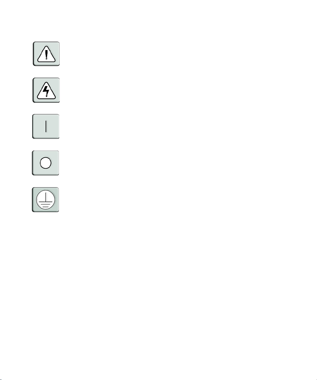
Instructions
This symbol is intended to alert the user to the presence of important operating and maintenance
(servicing) instructions in the literature accompanying the appliance.
Dangerous Voltage
This symbol is intended to alert the user to the presence of uninsulated dangerous voltage within the
product’s enclosure that may be of sufficient magnitude to constitute a risk of electric shock to persons.
Power On
This symbol indicates the principal on/off switch is in the on position.
Power Off
This symbol indicates the principal on/off switch is in the off position.
Protective Grounding Terminal
This symbol indicates a terminal which must be connected to earth ground prior to making any other connections to the equipment.

TABLE OF CONTENTS
Table of Contents
List of Tables..................................................................................................................vii
List of Figures .................................................................................................................ix
Chapter 1: Product Overview.......................................................................................... 1
Features and Benefits ........................................................................................................................1
Reduce cable bulk....................................................................................................................... 2
On-board Web Interface.............................................................................................................2
Safety Precautions .............................................................................................................................4
Rack Mount Safety Considerations....................................................................................................4
Chapter 2: Installation ..................................................................................................... 5
AutoView Switch Connectivity........................................................................................................... 5
Getting started ............................................................................................................................5
Installation overview ..................................................................................................................6
Connecting the AutoView 3100/3200 switch hardware ............................................................. 8
Verifying the Connections.................................................................................................................. 9
AutoView 3100/3200 switch .......................................................................................................9
Configuring the Web Interface ..........................................................................................................9
Adjusting Mouse Settings on Target Devices .................................................................................. 10
iii
Chapter 3: Local Port Operation................................................................................... 11
Controlling Your System at the Local Port......................................................................................11
Viewing and selecting ports and servers..................................................................................11
Viewing the status of your AutoView 3100/3200 switching system.......................................... 13
Navigating the OSCAR Interface..................................................................................................... 15
Configuring OSCAR Interface Menus ............................................................................................. 16
Managing server tasks using the OSCAR interface..................................................................30
Chapter 4: Web Interface Operations........................................................................... 37
Overview of the AutoView 3100/3200 Switch Web Interface ..........................................................37
Viewing and Selecting Ports and Servers........................................................................................ 37
About the AutoView Explorer Window............................................................................................38
Using the side navigation bar...................................................................................................39

iv AutoView 3100/3200 Switch Installer/User Guide
TABLE OF CONTENTS
Using the top option bar........................................................................................................... 40
Launching a KVM session ........................................................................................................41
Managing an AutoView switch web interface device............................................................... 41
Managing local accounts.......................................................................................................... 42
Managing device properties .....................................................................................................43
Chapter 5: The Video Viewer......................................................................................... 45
About the Video Viewer Window ..................................................................................................... 45
Video Viewer Minimum Requirements ............................................................................................ 45
Launching a KVM Session............................................................................................................... 46
Video Viewer Window Features ...................................................................................................... 47
Changing the toolbar................................................................................................................ 49
Setting the window size.............................................................................................................49
Adjusting the view..................................................................................................................... 50
Adjusting color depth................................................................................................................ 51
Additional video adjustment .....................................................................................................52
Adjusting mouse options........................................................................................................... 54
Using Keyboard Pass-through.........................................................................................................57
Using Macros................................................................................................................................... 58
Saving the View................................................................................................................................ 58
Closing a Video Viewer Window Session ........................................................................................ 59
Chapter 6: Terminal Operations ................................................................................... 61
The Console Menu ...........................................................................................................................61
Network Configuration ....................................................................................................................61
Other Console Main Menu Options.................................................................................................64
Security configuration ..............................................................................................................64
Local user accounts..................................................................................................................64
Console password.....................................................................................................................65
Firmware management.............................................................................................................65
Enable debug messages............................................................................................................ 65
Restore factory defaults............................................................................................................ 65
Reset appliance......................................................................................................................... 65
Exit............................................................................................................................................65

Table of Contents v
Appendices..................................................................................................................... 67
Appendix A: Flash Upgrades........................................................................................................... 67
Appendix B: Using AVRIQ-SRL modules........................................................................................69
Appendix C: UTP Cabling...............................................................................................................73
Appendix D: Technical Specifications............................................................................................. 75
Appendix E: Sun Advanced Key Emulation.....................................................................................77
Appendix F: Technical Support....................................................................................................... 79

vi AutoView 3100/3200 Switch Installer/User Guide

LIST OF TABLES
List of Tables
Table 3.1: Main Dialog Box Functions ...........................................................................................12
Table 3.2: OSCAR Interface Status Symbols...................................................................................13
Table 3.3: OSCAR Interface Navigation Basics ..............................................................................15
Table 3.4: Setup Features to Configure the OSCAR Interface........................................................ 16
Table 3.5: OSCAR Interface Status Flags .......................................................................................23
Table 3.6: Commands to Manage Routine Tasks for Your Target Devices ....................................31
Table 4.1: AutoView Explorer Window Area Descriptions .............................................................39
Table 4.2: Viewing Appliance Information...................................................................................... 43
Table 5.1: Video Viewer Window Description ................................................................................48
Table 5.2: Manual Video Adjust Dialog Box Descriptions .............................................................53
Table B.1: AVRIQ-SRL Module Pinouts.......................................................................................... 72
Table C.1: UTP Wiring Standards ..................................................................................................73
vii
Table E.1: Sun Key Emulation......................................................................................................... 77
Table E.2: PS/2-to-USB Keyboard Mappings ................................................................................. 78

viii AutoView 3100/3200 Switch Installer/User Guide

LIST OF FIGURES
List of Figures
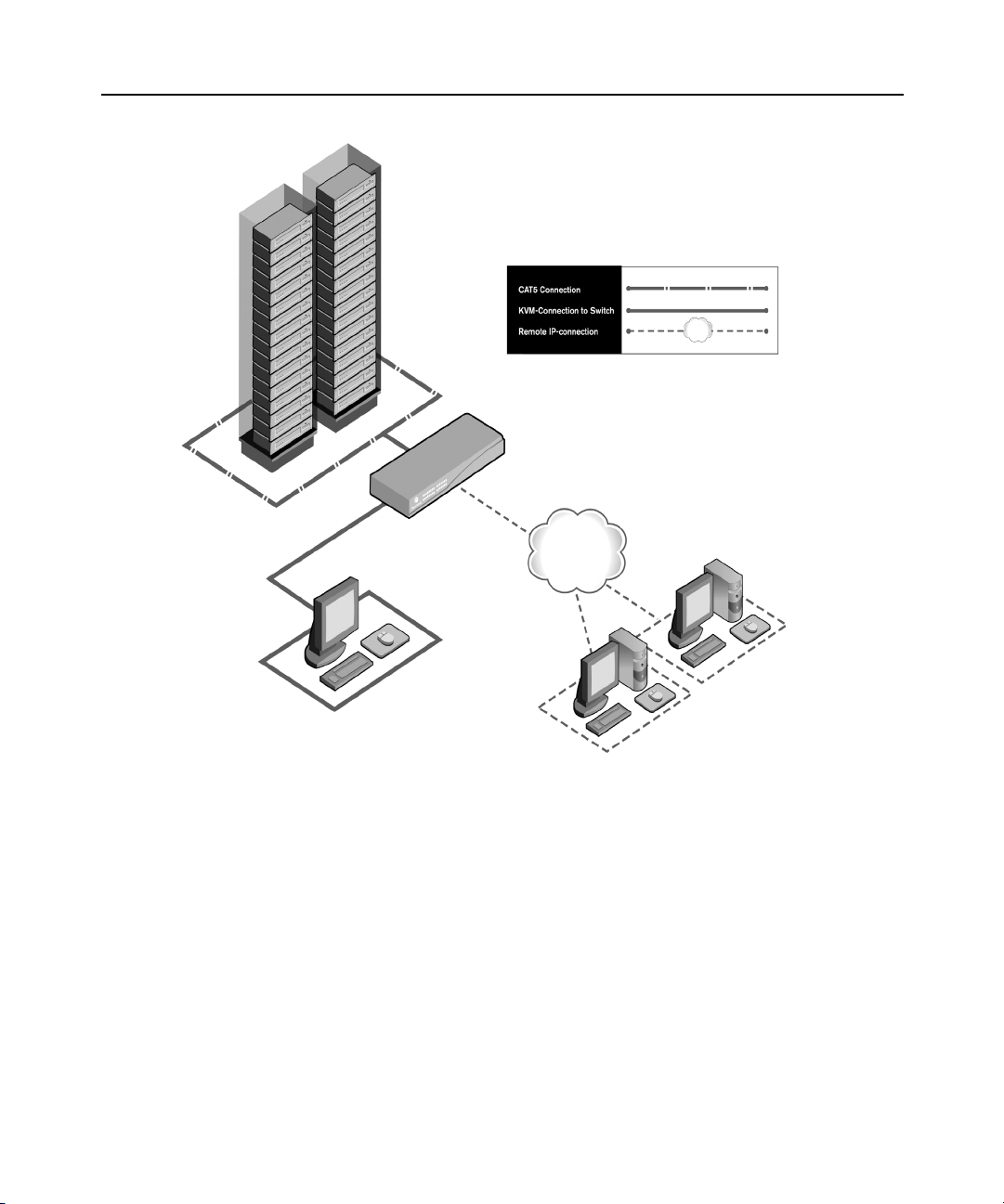
Figure 1.1: Example AutoView 3100/3200 Switch Configuration ....................................................3
Figure 2.1: Basic AutoView 3100 Switch Configuration .................................................................. 7
Figure 3.1: OSCAR Interface Main Dialog Box.............................................................................. 12
Figure 3.2: OSCAR Interface Setup Dialog Box ............................................................................. 17
Figure 3.3: OSCAR Interface Names Dialog Box...........................................................................18
Figure 3.4: OSCAR Interface Name Modify Dialog Box ................................................................ 19
Figure 3.5: OSCAR Interface Devices Dialog Box .........................................................................20
Figure 3.6: OSCAR Interface Device Modify Dialog Box...............................................................21
Figure 3.7: OSCAR Interface Menu Dialog Box............................................................................. 22
Figure 3.8: OSCAR Interface Flag Dialog Box .............................................................................. 23
Figure 3.9: Position Flag ................................................................................................................ 24
Figure 3.10: OSCAR Interface Broadcast Dialog Box.................................................................... 25
Figure 3.11: OSCAR Interface Scan Dialog Box............................................................................ 26
Figure 3.12: OSCAR Interface Commands Dialog Box..................................................................27
Figure 3.13: OSCAR Interface Screen Saver Dialog Box ............................................................... 28
Figure 3.14: OSCAR Interface Keyboard Dialog Box ....................................................................30
Figure 3.15: OSCAR Interface Commands Dialog Box..................................................................32
Figure 3.16: OSCAR Interface User Status Dialog Box ................................................................. 33
Figure 3.17: OSCAR Interface Disconnect Dialog Box..................................................................33
Figure 3.18: OSCAR Interface Version Dialog Box........................................................................ 35
Figure 3.19: IQ Selection Dialog Box.............................................................................................35
Figure 3.20: IQ Version Dialog Box...............................................................................................36
Figure 4.1: Avocent AutoView Explorer Window ........................................................................... 38
Figure 4.2: Side Navigation Bar...................................................................................................... 39
Figure 5.1: Video Viewer Window (Normal Window Mode) .......................................................... 47
Figure 5.2: Manual Video Adjust Dialog Box.................................................................................52
Figure 5.3: Video Viewer Window with Local and Remote Cursors Displayed ............................. 55
Figure 6.1: Console Main Menu......................................................................................................62
Figure 6.2: Network Configuration Menu.......................................................................................63
ix

x AutoView 3100/3200 Switch Installer/User Guide

CHAPTER
Product Overview
1
Features and Benefits
Avocent AutoView® switches combine analog and digital technology to provide flexible,
centralized control of data center servers. They provide customers with a significant reduction of
cable volume, secure remote access and flexible server management from anywhere at anytime.
Each AutoView 3100/3200 switch model consists of the following features:
• a rack mountable keyboard, video and mouse (KVM) switch, configurable for analog (local) or
digital (remote) connectivity
• supports Universal Serial Bus (USB) keyboards and mice
• video resolutions supported up to 1280 x 1024 for remote users
• enhanced video quality of up to 1600 x 1200 available to local users via the video port
• user peripheral ports for PS/2 and USB keyboards and mice
• accessibility to target devices across a 1000BaseT LAN port
• accessibility to target devices directly through a local port
The AutoView 3100/3200 switches give you flexible target device management control from
anywhere in the world.
1

2 AutoView 3100/3200 Switch Installer/User Guide
Reduce cable bulk
With server densities continually increasing, cable bulk remains a major concern for network
administrators. The AutoView 3100/3200 switches significantly reduce KVM cable volume in the
rack by utilizing the innovative AVRIQ module and a single, industry-standard Unshielded
Twisted Pair (UTP) CAT 5 cabling.
The AVRIQ module is powered directly from the target device and provides Keep Alive
functionality when the AutoView 3100/3200 switch is not powered.
The AVRIQ-SRL (serial) module is a DCE device that provides the primary interface between a
serial device and 1021/10221024an AutoView 3100/3200 switch. It provides VT100 terminal
emulation, break suppression and port history in a compact, convenient module.
On-board Web Interface
The AutoView 3100/3200 switch also provides a built-in web interface to handle all KVM
switching needs. Featuring secure “point-and-click” web browser-based access to control any
attached device, the AutoView switch web interface provides a Video Viewer window that allows
you to control the keyboard, monitor and mouse functions of the connected target device in real
time. See Chapter 4 for more details.
Chapter 1: Product Overview 3
AutoView 3200 Switch Shown
Ethernet
Analog User
®
(OSCAR
Graphical
User Interface)
Figure 1.1: Example AutoView 3100/3200 Switch Configuration
Digital User
(Computer with Internet Browser)

4 AutoView 3100/3200 Switch Installer/User Guide
Safety Precautions
To avoid potential video and/or keyboard problems when using Avocent products:
• If the building has 3-phase AC power, ensure that the computer and monitor are on the same phase.
For best results, they should be on the same circuit.
To avoid potentially fatal shock hazard and possible damage to equipment, please observe the
following precautions:
• Do not use a 2-wire power cord in any Avocent product configuration.
• Test AC outlets at the target device and monitor for proper polarity and grounding.
• Use only with grounded outlets at both the target device and monitor. When using a backup
Uninterruptible Power Supply (UPS), power the target device, the monitor and the AutoView 3100/
3200 switch from the UPS.
NOTE: The AC inlet is the main power disconnect.
Rack Mount Safety Considerations
• Elevated Ambient Temperature: If installed in a closed rack assembly, the operating temperature of
the rack environment may be greater than room ambient. Use care not to exceed the rated maximum
ambient temperature of the switch.
• Reduced Air Flow: Installation of the equipment in a rack should be such that the amount of airflow
required for safe operation of the equipment is not compromised.
• Mechanical Loading: Mounting of the equipment in the rack should be such that a hazardous
condition is not achieved due to uneven mechanical loading.
• Circuit Overloading: Consideration should be given to the connection of the equipment to the supply
circuit and the effect that overloading of circuits might have on overcurrent protection and supply
wiring. Consider equipment nameplate ratings for maximum current. Consideration should be given
to the connection of the equipment to the supply circuit and the effect that overloading of circuits
might have on overcurrent protection and supply wiring. Consider equipment nameplate ratings for
maximum current.
• Reliable Earthing: Reliable earthing of rack mounted equipment should be maintained. Pay
particular attention to supply connections other than direct connections to the branch circuit (for
example, use of power strips). Reliable earthing of equipment should be maintained. Pay particular
attention to supply connections other than direct connections to the branch circuit (for example, use
of power strips).

CHAPTER
Installation
2
AutoView Switch Connectivity
The AutoView 3100/3200 switching system transmits keyboard, video and mouse (KVM)
information between operators and target devices attached to the AutoView 3100/3200 switch over
a network using an Ethernet connection.
The AutoView 3100/3200 switch uses TCP/IP for communication over Ethernet. Although
10BaseT Ethernet may be used, Avocent recommends a dedicated, switched 100BaseT network, or
even a 1000BaseT network.
Getting started
5
Before installing your AutoView 3100/3200 switch, refer to the following lists to ensure you have all
items that shipped with it, as well as other items necessary for proper installation.
Supplied with the AutoView 3100/3200 switch
• Local country power cord
• Rack mounting brackets
• AutoView Installer/User Guide (this manual)
• AutoView 3100/3200 Quick Installation Guide
• Four self-adhesive rubber feet (shipped unattached)
• Null modem cable
Additional items needed
• One AVRIQ module per target server or AVRIQ-SRL module per serial device
• One CAT 5 patch cable per AVRIQ module (4-pair UTP, up to 10 meters)
• One CAT 5 patch cable for network connectivity (4-pair UTP, up to 10 meters)
NOTE: All references to IQ modules in this document use the AVRIQ module as a default. The AutoView 3100/
3200 switches support Avocent AVRIQ, DSRIQ and DSAVIQ modules as well as Avocent Integrated Access
Cables (IAC modules).

6 AutoView 3100/3200 Switch Installer/User Guide
Installation overview
The general procedure for setting up and installing the AutoView 3100/3200 switch is as follows:
• Unpack the AutoView 3100/3200 switch and verify that all components are present and in
good condition.
• Make all hardware connections between the power source, AutoView 3100/3200 switch, target
devices and the Ethernet.
• Turn on the power and verify that all connections are working.
• Configure the AutoView 3100/3200 switch using the console menu interface.
• Make the appropriate mouse setting adjustments.
Figure 2.1 on page 7 illustrates a basic configuration for the AutoView 3100/3200 switch, using the
AutoView 3100 switch as a model for the example.
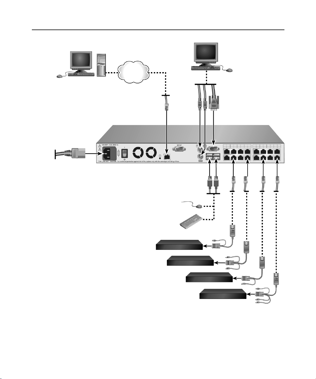
Digital User
AutoView 3100 Switch
Chapter 2: Installation 7
Analog User
Network
Power
Cord
Servers 1-16
Figure 2.1: Basic AutoView 3100 Switch Configuration
Ports
1-16
Local USB
Connections
AVRIQ/IAC modules,
PS/2, USB*, Sun and
serial adaptors
are available.

8 AutoView 3100/3200 Switch Installer/User Guide
Connecting the AutoView 3100/3200 switch hardware
NOTE: The AutoView 3100/3200 switch may be rack mounted in a 1U configuration. The AutoView 3100/
3200 switch does not support a 0U configuration.
To connect and power up your AutoView 3100/3200 switch:
1. Power down the target device(s) that will be part of your AutoView 3100/3200 switching
system. Locate the power cord that came with the switch and plug one end into the power
socket on the rear of the switch. Plug the other end into an appropriate AC wall
WARNING: To reduce the risk of electric shock or damage to your equipment:
- Do not disable the power cord grounding plug. The grounding plug is an important safety feature.
- Plug the power cord into a grounded (earthed) outlet that is easily accessible at all times.
- Disconnect the power from the switch by unplugging the power cord from either the electrical outlet or
the appliance.
2. Plug your VGA monitor and either PS/2 or USB keyboard and mouse cables into the
appropriately labeled switch ports. You must install both a keyboard and mouse on the local
ports or the keyboard will not initialize properly.
3. Choose an available numbered port on the rear of your AutoView 3100/3200 switch. Plug one
end of a CAT 5 patch cable (4-pair, up to 10 meters) into the selected port and plug the other
end into the RJ-45 connector of an AVRIQ module.
4. Attach the color-coded connectors of an AVRIQ module to the corresponding keyboard,
monitor and mouse ports on the server you will be connecting to the switch.
outlet.
NOTE: When connecting a Sun AVRIQ module, you must use a multi-sync monitor in the local port to
accommodate Sun computers that support both VGA and sync-on-green or composite sync.
5. Attach one end of the CAT 5 patch cable to the RJ-45 connector on the AVRIQ module.
Connect the other end of the CAT 5 patch cable to the desired port on the back of your
AutoView 3100/3200
switch.
6. Plug a CAT 5 patch cable from your Ethernet network into the LAN port on the back of your
switch. Network users will access the AutoView 3100/3200 switch through this port.
7. Power up each target device and then power up the AutoView 3100/3200 switch. After
approximately one minute, the switch completes initialization and displays the OSCAR
®
graphical user interface Free tag on the local port monitor.
To connect an AVRIQ module to a serial device:
1. Attach the AVRIQ-SRL module 9-pin serial connector to the serial port of the device to be
connected to your AutoView 3100/3200 switch.
2. Attach one end of the CAT 5 cable to the RJ-45 connector on the AVRIQ-SRL module.
Connect the other end of the CAT 5 patch cable to the desired port on the back of your switch.
NOTE: The AVRIQ-SRL module is a DCE device and only supports VT100 terminal emulation.

3. Connect the power supply to the power connector on your AVRIQ-SRL module. The cable
expander can be used to power up to four AVRIQ-SRL modules from a single power supply.
4. Connect the AVRIQ-SRL module power supply to a grounded AC wall outlet. Power up your
serial device.
Setting up your network for the on-board web interface
AutoView switching systems that have the on-board web interface use IP addresses to uniquely
identify the switch and the target devices. The AutoView switch supports both Dynamic Host
Configuration Protocol (DHCP) and static IP addressing. Avocent recommends that IP addresses
be reserved for each switch and that they remain static while the AutoView switches are connected
to the network.
Verifying the Connections
AutoView 3100/3200 switch
The front panel of the AutoView 3100/3200 switch features LEDs indicating the status of the
Ethernet connection:
• The green LED, labeled Link, illuminates when a valid connection to the network is
established at a rate of 1000 Mbps and blinks when there is activity on the port.
• The amber LED illuminates when you are communicating at a rate of 100 Mbps when using an
Ethernet connection.
• If neither LED is illuminated, connection speed is at a rate of 10 Mbps.
Chapter 2: Installation 9
Additionally, the front panel of the AutoView 3100/3200 switch has LEDs for each port that
indicate the target device status:
• A green LED illuminates when the attached target device has power.
• An amber LED illuminates when that port is selected.
• The LEDs blink during a firmware upgrade.
Configuring the Web Interface
You can access the AutoView 3100/3200 switch through the local peripherals or via an embedded
web interface. Before using the web interface to access the switch, first specify an IP address
through the SETUP port on the back panel of the switch. See
how to use the SETUP port to configure the switch.
Chapter 6 for detailed instructions on

10 AutoView 3100/3200 Switch Installer/User Guide
Adjusting Mouse Settings on Target Devices
Before a computer connected to the AutoView 3100/3200 switch can be used, you must set the
target mouse speed and turn off acceleration. For machines running Microsoft
(Windows NT®, 2000, XP, Server 2003), use the default PS/2 mouse driver.
To ensure that the local mouse movement and remote cursor display remain in sync, mouse
acceleration needs to be set to “none” for all user accounts accessing a remote system using a KVM
switch. Mouse acceleration should also be set to “none” on every remote system. Special cursors
should not be used and cursor visibility options, such as pointer trails,
animations, cursor shadowing and cursor hiding should also be turned off.
® Windows®
Ctrl key cursor location

CHAPTER
Local Port Operation
3
Controlling Your System at the Local Port
The AutoView 3100/3200 switch includes a local port on the back. This port enables you to connect
a keyboard, monitor and mouse to the switch for direct access. The AutoView 3100/3200 switch
uses the OSCAR graphical user interface, which has intuitive menus to configure your system and
select target devices. Targets can be identified by customizable names.
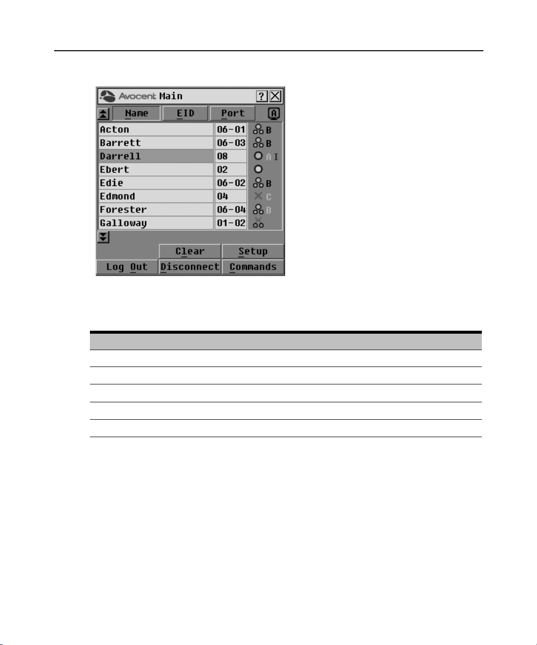
Viewing and selecting ports and servers
Use the Main dialog box to view, configure and control target devices in the AutoView 3100/3200
switching system. You may view the target devices by name, port or by the unique Electronic ID
(EID) embedded in each AVRIQ module. You will see an OSCAR interface-generated port list by
default when you first launch the OSCAR interface.
11
The Port column indicates the port to which a target device is connected.
To access the OSCAR interface Main dialog box:
Press Print Screen to launch the OSCAR interface. The Main dialog box will appear.
12 AutoView 3100/3200 Switch Installer/User Guide
Figure 3.1: OSCAR Interface Main Dialog Box
Table 3.1: Main Dialog Box Functions
Button Function
Log Out Disconnect the KVM and user sessions.
Clear Clear all offline AVRIQ modules.
Disconnect Disconnect the KVM session.
Setup Access the Setup dialog box and configure the OSCAR interface.
Commands Access the Commands dialog box.
To manage a KVM session from the Main dialog box:
Click Clear to clear all offline AVRIQ modules.
-or-
Click Disconnect to disconnect a KVM session.
Chapter 3: Local Port Operation 13
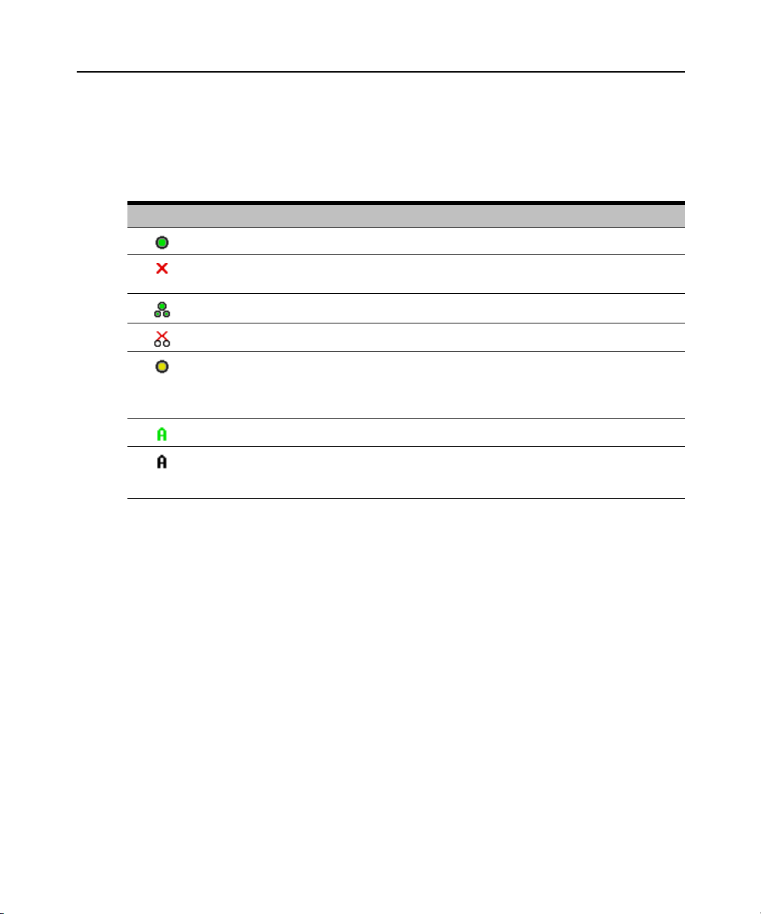
Viewing the status of your AutoView 3100/3200 switching system
The status of target devices in your system is indicated in the far right columns of the Main dialog
box. The following table describes the status symbols.
Table 3.2: OSCAR Interface Status Symbols
Symbol Description
(green circle) Server connected, powered up and the AVRIQ module is online.
Connected target device is powered down or is not operating properly and the AVRIQ module
is offline.
Connected switch is online.
Connected switch is offline or not operating properly.
(yellow circle) The designated AVRIQ module is being upgraded. When this symbol displays,
do not cycle power to the AutoView 3100/3200 switch or connected target devices and do not
disconnect AVRIQ modules. Doing so may render the module permanently inoperable and
require the AVRIQ module to be returned to the factory for repair.
(green letter) AVRIQ module is being accessed by the indicated user channel.
(black letter) AVRIQ module is blocked by the indicated user channel. For instance, in Figure
3.1, user B is viewing Forester, but is blocking access to Acton, Barrett and Edie which are
connected to the same AVRIQ module.
Selecting target devices
Use the Main dialog box to select target devices. When you select a target device, the AutoView 3100/
3200 switch reconfigures the keyboard and mouse to the settings for the selected target device.
To select target devices:
Double-click the target device name, EID or port number.
-or-
If the display order of your list is by port (Port button is depressed), type the port number and
press Enter.
-or-
If the display order of your list is by name or EID (Name or EID button is depressed), type the first
few letters of the name of the target device, or the EID number to establish it as unique and
press Enter.

14 AutoView 3100/3200 Switch Installer/User Guide
To select the previous target device:
Press Print Screen and then Backspace. This key combination toggles you between the previous
and current connections.
To disconnect from a target device:
Press Print Screen and then Alt+0 (zero). This leaves the user in a free state, with no target device
selected. The status flag on your desktop displays Free.
Soft switching
Soft switching is the ability to switch target devices using a hotkey sequence. You can soft switch
to a target device by pressing
Print Screen and then typing the first few characters of its name or
number. If you have set a Screen Delay Time and you press the key sequences before that time has
elapsed, the OSCAR interface will not display.
To configure the OSCAR interface screen delay:
1. Press Print Screen to launch the OSCAR interface. The Main dialog box appears.
2. Click Setup - Menu. The Menu dialog box appears.
3. For Screen Delay Time, type the number of seconds of delay desired before the Main dialog
box is displayed after
Print Screen is pressed.
4. Click OK.
To soft switch to a target device:
1. Press Print Screen. If the display order of the Main dialog is by port (Port button is depressed),
type the port number and press
Enter.
-or-
If the display order of the Main dialog is by name (Name button is depressed), type the first
few letters of the name of the target device to establish it as unique and press
Enter.
2. To switch back to the previous target device, press Print Screen then Backspace.

Navigating the OSCAR Interface
This table describes how to navigate the OSCAR interface using the keyboard and mouse.
Table 3.3: OSCAR Interface Navigation Basics
Keystroke Function
Chapter 3: Local Port Operation 15
Print Screen Opens the OSCAR interface. Press Print Screen twice to send the Print Screen keystroke to
F1 Opens the Help screen for the current dialog box.
Escape Closes the current dialog box without saving changes and returns to the previous one. If the
Alt Opens dialog boxes, selects or checks options and executes actions when used with underlined
Alt+X Closes current dialog box and returns to previous one.
Alt+O Selects the
Enter Completes a switch operation in the Main dialog box and exits the OSCAR interface.
Single-click,
Enter
Print Screen,
Backspace
Print Screen,
Alt+0 (zero)
Print Screen,
Pause
the currently selected AVRIQ module.
Main dialog box is displayed, pressing Escape closes the OSCAR interface and displays a
status flag if status flags are enabled. See
information. In a message box, pressing Escape closes the pop-up box and returns to the
current dialog box.
or other designated letters.
OK
button, then returns to the previous dialog box.
In a text box, single-clicking an entry and pressing Enter selects the text for editing and
enables the Left and Right Arrow keys to move the cursor. Press Enter again to exit.
Toggles back to previous selection.
Immediately disengages user from a target device; no target device is selected. Status flag
displays
Immediately turns on Screen Saver mode and prevents access to that specific console, if it is
password protected.
Free
. (This only applies to the 0 (zero) on the keyboard and not the numeric keypad.)
Controlling the status flag
in this chapter for more
Up/Down
Arrows
Right/Left
Arrows
Page Up/Page
Down
Home/End Moves the cursor to the top or bottom of a list.
Backspace Erases characters in a text box.
Delete Deletes current selection in the Scan list or characters in a text box.
Moves the cursor from line to line in lists.
Moves the cursor between columns. When editing a text box, these keys move the cursor
within the column.
Pages up and down through Name and Port lists and Help pages.

16 AutoView 3100/3200 Switch Installer/User Guide
Table 3.3: OSCAR Interface Navigation Basics (Continued)
Keystroke Function
Shift-Del Deletes from the current selection to the end of the list when editing a Scan list.
Numbers Type from the keyboard or keypad.
Caps Lock Disabled. Use the Shift key to change case.
Backspace Erases characters in a text box.
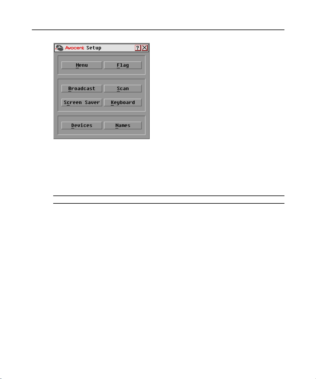
Configuring OSCAR Interface Menus
You can configure your AutoView 3100/3200 switching system from the Setup dialog box within
the OSCAR interface. Select the Names button when initially setting up your switching system to
identify target devices by unique names. Select the other setup features to manage routine tasks for
your target devices from the OSCAR interface menu.
using each of the buttons in the Setup dialog box as shown in Figure 3.2.
Table 3.4: Setup Features to Configure the OSCAR Interface
Feature Purpose
Table 3.4 outlines the function accessed
Menu Change the Main dialog box list sorting option by toggling between numerically by port or EID
number and alphabetically by name. Change the Screen Delay Time before the OSCAR
interface displays after pressing Print Screen.
Flag Change display, timing, color or location of the status flag.
Broadcast Simultaneously send mouse movements and keystrokes to multiple target devices.
Scan Set up a custom Scan pattern for up to 16 target devices.
Screen Saver Set passwords to protect or restrict access or enable the screen saver.
Keyboard Set the keyboard country code to send to Sun servers.
Devices Identify the appropriate number of ports on an attached cascade switch.
Names Identify target devices by unique names.
To access the OSCAR interface Setup dialog box:
1. Press Print Screen to launch the OSCAR interface. The Main dialog box appears.
2. Click Setup to open the Setup dialog box.
Chapter 3: Local Port Operation 17
Figure 3.2: OSCAR Interface Setup Dialog Box
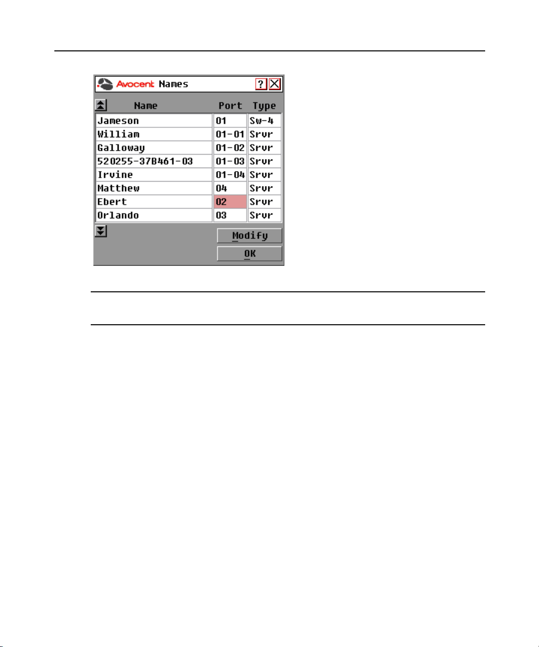
Assigning target device names
Use the Names dialog box to identify target devices by name rather than by port number. The
Names list is always sorted by port order. You can toggle between displaying the name or the EID
number of each AVRIQ module, so even if you move the target device to another port, the name
and configuration will be recognized by the switch.
NOTE: If a target device is turned off, its respective AVRIQ module will not appear in the Names list.
To access the OSCAR interface Names dialog box:
1. If the OSCAR interface is not open, press Print Screen. The Main dialog box appears.
2. Click Setup - Names to open the Names dialog box as shown in Figure 3.3.
18 AutoView 3100/3200 Switch Installer/User Guide
Figure 3.3: OSCAR Interface Names Dialog Box
NOTE: If new AVRIQ modules are discovered by the AutoView 3100/3200 switch, the on-screen list will be
automatically updated. The mouse cursor will change into an hourglass during the update. No mouse or
keyboard input will be accepted until the list update is complete.
To assign names to target devices:
1. In the Names dialog box, select a target device name or port number and click Modify to open
the Name Modify dialog box as shown in
Figure 3.4 on page 19.
Loading...