


 Loading...
AT&T
PARTNER® II Centrex
Communications System
Release 1
Installation and Use
Copyright © 1991 AT&T |
AT&T 518-455-330 |
All Rights Reserved |
Issue 1 |
Printed in U.S.A. |
November 1991 |
Notice
Every effort was made to ensure that the information in this book was complete and accurate at the time of printing. However, information is subject to change.
Federal Communications Commission (FCC) Interference Notice
This equipment has been tested and found to comply with the limits for a Class A digital device, pursuant to Part 15 of FCC rules. These limits are designed to provide reasonable protection against harmful interference when the equipment is operated in a commercial environment. This equipment generates, uses, and can radiate radio frequency energy and, if not installed and used in accordance with the instruction manual, may cause harmful interference to radio communications. Operation of this equipment in a residential area is likely to cause harmful interference, in which case the user will have to correct the interference at his or her own expense. For additional FCC interference, registration, and repair information, see Appendix E of this book.
Trademarks
MLS-34D, MLS-12D, MLS-12, MLS-6, MLC-6, and SYSTIMAX are trademarks of AT&T. PARTNER, Magic on Hold, MERLIN, and PagePac6 are registered trademarks of AT&T. ESSX is a registered trademark of Bell South Corporation.
CENTRON is a registered trademark of U S West, Inc.
Plexar is a registered trademark of Southwestern Bell Telephone.
Warranty
AT&T provides a limited warranty to this product. Refer to “AT&T Limited Warranty and Limitation of Liability” in Appendix C.
Ordering Information
The order number for this book is 518-455-330. To order copies of this book, call 1 800 432-6600 in the U.S. and 1 800 255-1242 in Canada. For more information on how to order this and other system reference materials, see “Reference Materials” in “About This Guide.” For information on ordering replacement parts, accessories, and other compatible equipment, refer to “Product Ordering Information” in Appendix C.
Support Telephone Numbers
In the U.S., AT&T provides a toll-free customer helpline 24 hours a day. Call the AT&T Helpline at 1 800 628-2888 if you need assistance when installing, programming, or using your premises equipment.
For assistance in Canada, contact your local AT&T authorized dealer.

Contents
|
|
|
|
v |
|
|
|
|
|
About This Guide |
|
|
|
||
|
|
|
|
|
|
|
|
|
|
|
|
|
|
|
|
|
1 |
Overview |
1-i |
|
|
|
|
|
|
■ |
Terminology |
1-1 |
|
|
|
|
|
■ Using Premises Equipment to Complement |
|
|
|
|
|
|
|
|
Centrex Services |
1-3 |
|
|
|
|
|
■ Primary and Secondary Lines |
1-5 |
|
|
|
|
|
|
■ |
Features and Capabilities |
1-6 |
|
|
|
|
|
■ |
Premises Equipment |
1-7 |
|
|
|
|
|
|
|
|
|
|
|
|
|
|
|
|
|
|
|
|
2 |
Installing the Equipment |
2-i |
|
|
|
|
|
|
■ |
Important Safety Instructions |
2-ii |
|
|
|
|
|
■ |
Terminology |
2-1 |
|
|
|
|
|
■ |
Installation Guidelines |
2-3 |
|
|
|
|
|
■ |
Example Configuration |
2-6 |
|
|
|
|
|
■ |
Installation Procedures |
2-8 |
|
|
|
|
|
■ |
Equipment Upgrades |
2-14 |
|
|
|
|
|
|
|
|
|
|
|
|
|
|
|
|
|
|
|
|
3 |
Using the Equipment with Centrex Services |
3-i |
|
|
|
|
|
|
■ |
Overview |
3-1 |
|
|
|
|
|
■ |
Terminology |
3-2 |
|
|
|
|
|
■ Centrex Line Assignments and Ringing |
3-3 |
|
|
|
|
|
|
■ |
Centrex Services |
3-5 |
|
|
|
|
|
■ One-Touch Access to Centrex Services |
3-6 |
|
|
|
|
|
|
|
|
|
|
|
|
|
|
|
|
|
|
|
|
|
4 |
Decisions for Customizing Your System |
4-i |
|
|
|
|
|
|
■ |
Overview |
4-1 |
|
|
|
|
|
■ |
Terminology |
4-2 |
|
|
|
|
|
■ |
Call Coverage Options |
4-3 |
|
|
|
|
|
■ One-Touch Access to Equipment Features |
4-10 |
|
|
|
|
|
|
■ Optional Features for Premises Equipment |
4-13 |
|
|
|
|
|
|
■ |
Auxiliary Equipment |
4-22 |
|
|
|
|
|
■ Identifying the Equipment Features You Need |
4-24 |
|
|
|
|
Contents i
|
|
Programming Reference |
|
|
|
|
|
5 |
5-i |
||||||
|
|
■ Alphabetical List of System and Telephone |
|
|
|
|
|
|
|
|
Programming Procedures |
5-ii |
|||
|
|
■ |
Overview |
5-1 |
|
|
|
|
|
■ |
Terminology |
5-2 |
|
|
|
|
|
■ |
System Programming Procedures |
5-3 |
|
|
|
|
|
■ |
Telephone Programming Procedures |
5-4 |
|
|
|
|
|
■ Changing Settings after Installation |
5-7 |
|
|
|
|
|
|
■ |
System Programming Reference |
5-10 |
|
|
|
|
|
■ System Speed Dial Programming Reference |
5-14 |
|
|
|
|
|
|
■ |
Telephone Programming Reference |
5-15 |
|
|
|
|
|
|
|
|
|
|
|
|
|
|
|
|
|
|
|
6 |
Using Telephones |
6-i |
|||||
|
|
■ |
Overview |
6-1 |
|
|
|
|
|
■ |
Terminology |
6-1 |
|
|
|
|
|
■ |
MLSand MLC-Model Telephones |
6-2 |
|
|
|
|
|
■ |
Standard Telephones |
6-7 |
|
|
|
|
|
■ |
Combination Extensions |
6-9 |
|
|
|
|
|
■ |
Equipment Features |
6-10 |
|
|
|
|
|
■ |
Using Your Telephone |
6-12 |
|
|
|
|
|
|
|
|
|
|
|
|
|
|
|
|
|
|
|
7 |
Using Auxiliary Equipment |
7-i |
|||||
|
|
■ |
Terminology |
7-1 |
|
|
|
|
|
■ |
Fax Machines |
7-1 |
|
|
|
|
|
■ |
Answering Machines |
7-5 |
|
|
|
|
|
■ |
Modems |
7-6 |
|
|
|
|
|
■ |
Credit Card Scanners |
7-7 |
|
|
|
|
|
■ Call Reporting Devices (SMDR) |
7-7 |
|
|
|
|
|
|
|
|
|
|
|
|
|
|
|
|
|
|
|
|
AUser Forms
■Form A: Speed Dial Numbers
■Form B: Centrex Extension Numbers
A-1 A-2 A-3
|
|
|
B |
Using Intercom Features |
B-1 |
■Using the Intercom on MLSand MLC-Model
Telephones |
B-1 |
■ Using Intercom Calling Features |
B-3 |
ii Contents

CMaintenance and Customer Support
■Maintenance
■In Case of Difficulty
■Repair Information
■AT&T Limited Warranty and Limitation of Liability
■Product Ordering Information
C-1 C-1 C-2 C-9 C-9 C-11
|
|
|
|
|
D |
Specifications |
D-1 |
||
|
|
|
|
|
|
|
|
|
|
E |
FCC Information |
E-1 |
||
|
|
|
■ Federal Communications Commission (FCC) |
|
|
|
|
Interference Information |
E-1 |
|
|
|
|
|
|
|
|
Feedback Form |
|
|
|
|
|
|
|
|
|
|
|
|
|
|
|
|
GL |
Glossary |
GL-1 |
||
|
|
|
|
|
|
|
|
|
|
IN |
Index |
IN-1 |
||
|
|
|
|
|
|
|
|
Programming Quick Reference |
Inside back cover |
|
|
|
||
Contents iii

About This Guide
Purpose
The system described in this guide consists of premises equipment and Centrex services. Although the terms “premises equipment,” “Centrex services,” and “system” have broader meanings elsewhere, this guide uses those terms to refer specifically to the following definitions:
■ Premises equipment refers to the AT&T equipment controller and MLSand MLC-model telephones that you purchased as part of your Partner® II Centrex Communications System, plus all other telecommunications devices connected to your equipment controller. This equipment is installed at your place of business.
■Centrex services include the Centrex lines that are connected to the equipment controller and the features available on those Centrex lines. These services (which may be offered in your area under a different name such as ESSX,® CENTRON,® or Plexar®) must be arranged for
separately with your local telephone company.
■System refers to the combination of premises equipment and Centrex services described above.
The main purpose of this guide is to provide instructions for installing, programming, and using your premises equipment. Because the selection of services available from the local phone companies continually expands and changes—to keep pace with the needs of businesses and with technological advances in the world of communications—this guide does not provide detailed information about Centrex services. For specific information about your Centrex services, see the Centrex documentation provided by your local telephone company.
About This Guide v

Terminology
The following terms are used throughout this guide, and are important for understanding how your system works. In addition, each chapter in this guide begins with a “Terminology” section that defines key terms used in the chapter. All terms are also defined in the Glossary.
Centrex
Centrex system
Equipment controller
Telephone services that your local telephone company provides from a Central Office (CO) located outside your business premises, including Centrex lines connected to the equipment controller and the features available on those Centrex lines. (Your telephone company may call Centrex by another name.)
The total block of Centrex lines you subscribe to—all or some of which may be connected to the equipment controller for your system—together with the Centrex services associated with those lines. See also Premises equipment and System.
The AT&T product that you purchased as part of your system. This product consists of a group of modules that connect Centrex lines coming into your building to the extensions in your system. The equipment controller also provides equipment features.
Equipment |
A feature provided by your equipment controller (as opposed |
feature |
to a service provided by Centrex). |
MLSand |
The AT&T telephones that you purchased as part of your |
MLC-model |
system. These telephones are specifically designed for use |
telephones |
with the equipment controller. Models include the MLS-34D™ |
|
telephone, MLS-12D™ telephone, MLS-12™ telephone, |
|
MLS-6™ telephone, and MLC-6™ telephone. |
Premises |
The AT&T equipment controller and the MLSand |
equipment |
MLC-model telephones that you purchased as part of your |
|
system, plus all other telecommunication devices that are |
|
connected to your equipment controller. For purposes of this |
|
guide, premises equipment does not include any equipment |
|
that connects directly to Centrex lines without going through |
|
the equipment controller. See also System and Centrex |
|
system. |
Standard |
An industry-standard touch-tone or rotary phone such as you |
phone |
might have in your home. Some standard phones include |
|
special feature buttons for frequently-used calling functions. |
System |
Your premises equipment, in combination with the Centrex |
|
lines that are connected to your equipment controller and the |
|
Centrex services that are available on those lines. See also |
|
Centrex system and Premises equipment. |
vi About This Guide

How to Use This Guide
This guide provides instructions and advice on the following topics:
■Installation. If you are installing the system for the first time, read Chapters 1 and 2 and Appendix D, which provide an overview of the system, instructions for equipment installation, and equipment specifications.
If your company already has modular jacks for all outside lines and extensions, you may be able to use the existing wiring to install the equipment controller and connect telephones yourself (see Chapter 2). If you prefer to have an AT&T service technician install and customize your premises equipment, call 1 800 247-7000 (in the U.S. only) or your AT&T authorized dealer.
Your system can include a wide variety of auxiliary equipment, including fax machines, modems, answering machines, credit card scanners, and call reporting (SMDR) devices. See Chapter 7 for advice on setting up these industry-standard devices to work effectively with your system.
■Setup Decisions. If you are a new user, read Chapters 1, 3, 4, and 6, to familiarize yourself with the features provided by your equipment controller, to learn how to program the equipment controller and individual phones, and to learn how to handle calls.
Chapter 3 explains how your equipment controller complements Centrex services, providing a variety of features that support Centrex capabilities and making it easy for you to access Centrex features. Chapter 4 helps you make decisions about customizing the premises equipment, to use additional features and capabilities provided by your equipment. Chapter 6 provides call-handling instructions for standard phones and for MLSor MLC-model phones.
■Programming. Chapter 5 gives step-by-step instructions for all of the programming procedures for your premises equipment. You can use the information in this chapter as a reference, to help you carry out your decisions about customizing your premises equipment.
■Making Changes. If you need to reprogram the premises equipment or individual extensions, see Chapter 5, “Programming Reference,” or the Programming Quick Reference pages at the back of this book.
If you are adding equipment to your system, see Chapter 2, “Installing the Equipment,” Chapter 5, “Programming Reference,” and Chapter 7, “Using Auxiliary Equipment.”
■Training Co-Workers. Chapter 6 explains how to handle calls and use equipment features effectively. To help users get the most out of their phones, give each telephone user a Quick Reference card and filled-in copies of the “Speed Dial Numbers” form in theSystem Planner or Appendix A of this book.
About This Guide vii

Before training co-workers, read Appendix B to decide whether to make intercom calling features available to telephone users. (These equipment features require that users know the jack numbers where lines and extensions are connected to the equipment controller.) In addition, panels 6 and 7 of the Quick Reference card present intercom calling features.
■Solving Problems. Appendix C provides information on solving problems and ordering additional accessories and equipment. If your premises equipment malfunctions, you may be able to solve the problem by following the steps provided in “Troubleshooting,” starting on page C-3.
■Daily Operation. Depending on how your system is set up, you may need to oversee some of the system’s daily operations. For example, if you use the Night Service feature available with your equipment controller, you will need to turn on Night Service at the end of each day before leaving the office. (See “Using Night Service” on page 6-18.)
Once you are experienced with the system, use the Table of Contents or Index to locate the information you need.
Product Safety Labels
This book contains several product safety statements, identified by a 
CAUTION:
Indicates the presence of a hazard that will or can cause minor personal injury or property damage if the hazard is not avoided.
WARNING:
Indicates the presence of a hazard that can cause severe or fatal personal injury if the hazard is not avoided.
Carefully read the WARNING statement on page 2-9. Opening the equipment modules or backplane will expose you to hazardous voltages, which can cause severe personal injury or death. Also, read “Important Safety Instructions” on page 2-ii before performing any installation procedures.
Reference Materials
The following reference materials are available to help you install, program, and use the premises equipment. To order them, call the AT&T Customer Information Center (1 800 432-6600 in the U.S. or 1 800 255-1242 in Canada). The order numbers are in parentheses:
■Installation and Use (518-455-330) provides instructions for installing, programming, and using the premises equipment.
■Quick Reference for Use with MLS-Series Telephones (518-455-331, package of 6) contains basic instructions for using MLS-model telephones.
viiiAbout This Guide

■MLC-6 Cordless Telephone: Installation and Troubleshooting
(999-506-143) explains how to install the MLC-6 cordless telephone and how to solve any problems that might occur when using it with your system.
■MLC-6 Cordless Telephone Quick Reference: Display and Controls
(999-506-146) explains how to use the MLC-6 cordless telephone with your system.
In addition, a System Planner (GBS-124) provides forms that you should use before you install your system—to determine your system configuration—and on an ongoing basis—to make sure that you have a current record of all the programming for your premises equipment. You can order the Planner from AT&T Forms Services at 1 800 367-6487.
How to Comment on This Guide
A feedback form is located at the end of this guide, after the appendixes. Use that form to send AT&T your comments on the product or this guide, or send your comments and recommendations for changes to:
A. Sherwood AT&T
99 Jefferson Road (Room 2A-25) Parsippany, NJ 07054
(FAX 201 887-6898)
About This Guide ix
|
|
1 |
|
Overview |
|
|
|
Contents
Terminology |
1-1 |
|
Using Premises Equipment to Complement |
|
|
|
Centrex Services |
1-3 |
Primary and Secondary Lines |
1-5 |
|
Features and Capabilities |
1-6 |
|
Premises Equipment |
1-7 |
|
■ |
Equipment Controller |
1-8 |
|
Modules |
1-8 |
|
Capacity |
1-8 |
■ |
MLSand MLC-Model Telephones |
1-9 |
■ |
Auxiliary Equipment |
1-9 |
|
Industry-Standard Devices |
1-10 |
|
Other Devices |
1-11 |
Overview 1-i

|
|
1 |
|
Overview |
|
|
|
Terminology
The following terms are used in this chapter. In addition, you may wish to review the “Terminology” section of “About This Guide,” which defines basic terms used throughout this guide, or the Glossary, which defines all terms.
Auto Dial |
A programmable telephone button that lets you dial a series |
button |
of digits simply by pressing that button. An Auto Dial button |
|
can be used to store a Centrex feature code or a telephone |
|
number so that it can be dialed with one touch. |
Auxiliary |
Telecommunications equipment (other than MLSand |
equipment |
MLC-model telephones) that can be connected to the |
|
equipment controller. Auxiliary equipment includes |
|
industry-standard devices that can connect directly to the |
|
public telephone network (such as standard phones or fax |
|
machines) as well as devices that require the interface |
|
provided by the equipment controller (such as a loudspeaker |
|
paging system). |
Centrex |
Telephone services that your local telephone company |
|
provides from a Central Office (CO) located outside your |
|
business premises, including Centrex lines connected to the |
|
equipment controller and the features available on those |
|
lines. (Your telephone company may call Centrex by another |
|
name.) |
Centrex |
A short code (or “Centrex extension ID”) that can be used to |
extension |
dial another extension within the Centrex system. Typically, |
number |
this is the last digits of the Centrex telephone number. |
Centrex system |
The total block of Centrex lines you subscribe to—all or some |
|
of which may be connected to the equipment controller for |
|
your system—together with the Centrex services associated |
|
with those lines. |
Overview 1-1
|
|
|
|
|
Equipment |
The AT&T product that you purchased as part of your |
|
|
Controller |
system. This product consists of a group of modules that |
|
|
|
connect Centrex lines coming into your building to the |
|
|
|
extensions in your system. The equipment controller also |
|
|
|
provides equipment features. |
|
|
Equipment |
A feature provided by your equipment controller (as opposed |
|
|
feature |
to a service provided by Centrex). |
|
|
Equipment |
A programmable telephone button on an MLSor MLC-model |
|
|
feature |
telephone that enables you to access an equipment feature |
|
|
button |
with one touch, simply by pressing the button. See also Auto |
|
|
|
Dial button and Programmable button. |
|
Extension
Extension jack
Feature phone
A destination in the system that can be dialed.
The location on 206 modules that allows you to connect phones (or other telecommunications devices) to the equipment controller.
An industry-standard phone that includes programmable buttons or other built-in features.
Intercom call |
A call that is made using the [ Intercom ] button on an MLSor |
|
MLC-model telephone, to call another system extension |
|
without tying up primary Centrex lines. |
Premises |
The AT&T equipment controller and MLSand MLC-model |
equipment |
telephones that you purchased as part of your system, plus |
|
all other telecommunications devices that are connected to |
|
your equipment controller. For purposes of this guide, |
|
premises equipment does not include any equipment that |
|
connects directly to Centrex lines without going through the |
|
equipment controller. See also System and Centrex system. |
Primary line
Programmable button
The main Centrex line assigned to an extension, generally used to place and receive all calls for that extension. When a caller dials a phone number, the call rings immediately at the extension where the line is assigned as a primary line (unless line ringing is changed to let another extension screen calls on the line). See also Secondary line.
A telephone button that can be set up to access a feature. On MLSand MLC-model phones, programmable buttons can be used as Auto Dial buttons (for one-touch dialing of Centrex feature codes or telephone numbers) or equipment feature buttons.
Secondary line |
A line assigned to an extension for call coverage purposes, |
|
generally with delayed or no ringing. When a call comes in |
|
on the line, it rings first at the extension where it is assigned |
|
as the primary line; only if there is no answer does it ring at |
|
the extension where it is a secondary line. See also Primary |
|
line. |
Standard |
An industry-standard touch-tone or rotary phone such as you |
phone |
might have in your home. Some standard phones include |
|
special feature buttons for frequently-used calling functions. |
1-2 Overview
|
|
|
|
|
System |
Your premises equipment, in combination with the Centrex |
|
|
|
lines that are connected to your equipment controller and the |
|
|
|
Centrex services that are available on those lines. See also |
|
|
|
Centrex system and Premises equipment. |
|
Using Premises Equipment
to Complement Centrex Services
The system discussed in this guide consists of two elements: Centrex services (including Centrex lines and associated features) and premises equipment (including the equipment controller, MLSand MLC-model telephones, and other telecommunications devices connected to the controller).
The Centrex services you receive from your local telephone company provide a unified telephone network for your business, even across different geographical locations, and give you services customized for your needs.
NOTE:
Your telephone company may offer Centrex services under a different name (for example, ESSX,® CENTRON,® or Plexar®). Also, you may be able to select different services for different lines. (For more information, see the Centrex documentation provided by your local telephone company.)
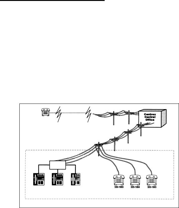
Your AT&T premises equipment is designed to complement the advantages offered by Centrex. All or some of your Centrex lines may be connected to the equipment controller. You can connect a maximum of 24 Centrex lines and 24 extensions to your equipment controller. Figure 1-1 shows an example in which some Centrex lines are connected to the equipment controller and some are not
Public Phone |
|
||
|
|
|
|
|
Network |
|
Centrex |
|
|
|
Central |
|
|
|
|
|
|
|
Office |
Your Centrex System
Your System
Equipment
Controller
555-1000 |
555-1001 |
555-1002 |
555-1003 |
555-1004 |
555-1005 |
Figure 1-1. Your Centrex System
Overview 1-3
Any Centrex lines that are not connected to the equipment controller, while they are part of the larger Centrex system, are not considered to be part of the system described in this guide. For example, a hospital might subscribe to a large block of Centrex lines, but connect only the lines for administrative personnel to the equipment controller. In this situation, the telephones for administrative personnel would be managed by the equipment controller as a distinct system within the larger Centrex system.
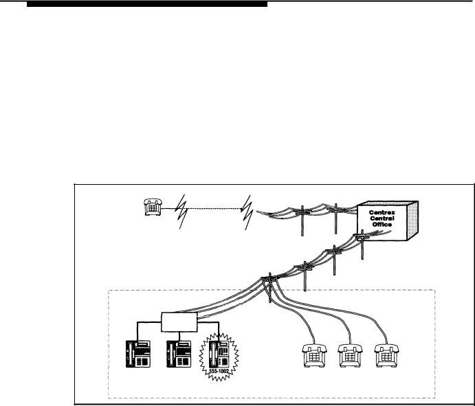
One of the most important Centrex features is the assignment of one Centrex line for each extension in your system. This allows a caller to reach an extension directly, simply by dialing the extension’s phone number, as shown in Figure 1-2. The call rings at the extension immediately, so you do not need to have a receptionist who answers calls for all system extensions and then transfers each call to the appropriate user.
|
Public Phone |
|
|
Network |
Centrex |
|
Central |
|
Caller dials 555-1002 |
|
|
|
Office |
Equipment
Controller
555-1000 |
555-1001 |
555-1003 |
555-1004 |
555-1005 |
Ringing
Figure 1-2. Dialing a System Extension
The equipment controller complements Centrex by automatically assigning a primary line to each extension (see “Primary and Secondary Lines” on the next page), and by passing Centrex ringing patterns through to phones. (The major benefits provided by your equipment controller and the AT&T phones that you connect to it are discussed in “Features and Capabilities” on page 1-6; in addition, Chapter 3 provides a more detailed discussion of the way your premises equipment and Centrex services work together.)
The equipment controller also provides optional features, some of which may be similar to Centrex services you have. (Optional equipment features are listed at the end of Chapter 4 in this guide.) If you have similar features available from Centrex and from the equipment controller, you should use the Centrex features.
NOTE:
The System Planner, available separately, provides forms you can use to plan your system configuration and to identify your Centrex services. If you do not already have a copy of the System Planner, see “Reference Materials” in “About This Guide.”
1-4 Overview

Primary and Secondary Lines
By default, each extension in your system gets one primary line that will be used to receive and place all calls for that extension. When the user at an extension picks up the handset to make an outgoing call, the primary line for the extension is automatically selected. Likewise, all incoming calls on the primary line ring immediately at the user’s phone. The primary line always appears on the bottom leftmost line button on an MLSor MLC-model phone. Except for Hotline phones and doorphones (see page 4-23), each extension in your system has a primary Centrex line.
You can also assign secondary lines to extensions. Secondary lines are lines other than the primary line, typically assigned to a phone for call coverage purposes. Secondary lines generally use delayed ringing; when a call comes in on a line, it rings first at the extension where the line is assigned as a primary line; only after about 20 seconds does it begin ringing at an extension where it is assigned as a secondary line. Likewise, when a user picks up the handset to make an outgoing call, the extension’s primary line is selected automatically. A secondary line is selected automatically only to answer an incoming call (if the call is already ringing at your phone when you pick up the handset).
All lines are automatically assigned to the first phone connected to the equipment controller; but only the line assigned to the bottom leftmost line button on the phone is primary. All of the other lines assigned to the extension are secondary lines. (This default line arrangement provides Central Call Coverage; for more information about this and other call coverage options, see page 4-3.)
NOTE:
Secondary lines assigned to an extension are used as primary lines at other extensions. To avoid tying up another user’s primary line, callers who have secondary lines should always use their own primary lines to make outgoing calls.
Overview 1-5

Features and Capabilities
Your equipment controller supports the following features to complement your Centrex services:
■Multiple line assignments, permitting more flexible call coverage. For example, the equipment controller automatically assigns all lines to the first phone connected to the equipment controller, to serve as a possible receptionist’s position. In addition, you have the option of assigning secondary lines at other phones, to provide Local Call Coverage, so that a person can answer calls on a line when the line’s primary user is absent or busy. The equipment controller also passes Centrex ringing patterns through to each phone (for example, to distinguish between outside and inside calls). When a line is assigned to an MLSor MLC-model phone, the lights on the line button let you see the activity on the line.
■Programmable buttons on MLSand MLC-model phones, providing one-touch access to both Centrex and equipment features). You can access a feature simply by pressing the button.
■Easy-to-use programming procedures, making it easy for you to manage your system. You can change line assignments, call coverage arrangements, or programmable buttons, quickly and easily. (The display on an MLS-34D or MLS-12D phone provides feedback during programming.)
■Modular connections to the equipment controller, making it easy for you to reconfigure your system or to add extensions as your system grows.
■Direct connections for industry-standard devices—including standard phones, fax machines, answering machines, modems, and credit card scanners.
■Optional equipment features, including paging over a loudspeaker paging system or over MLS-model phone speakers, music on hold*, call detail recording (also known as Station Message Detail Recording, or SMDR), night service operation, speed dialing, line access restrictions, and many others.
■Power failure operation with standard phones, allowing you to make and answer calls during a power failure while retaining programmed equipment settings for up to four days. (An optional Uninterruptible Power Supply, or UPS, is also available to allow full equipment operation during a power failure.)
*
If you use equipment that rebroadcasts music or other copyrighted materials, you may be required to obtain a license from a third party such as ASCAP or BMI. Or, you can purchase a Magic on Hold® device from AT&T that does not require you to obtain such a license.
1-6 Overview
Premises Equipment
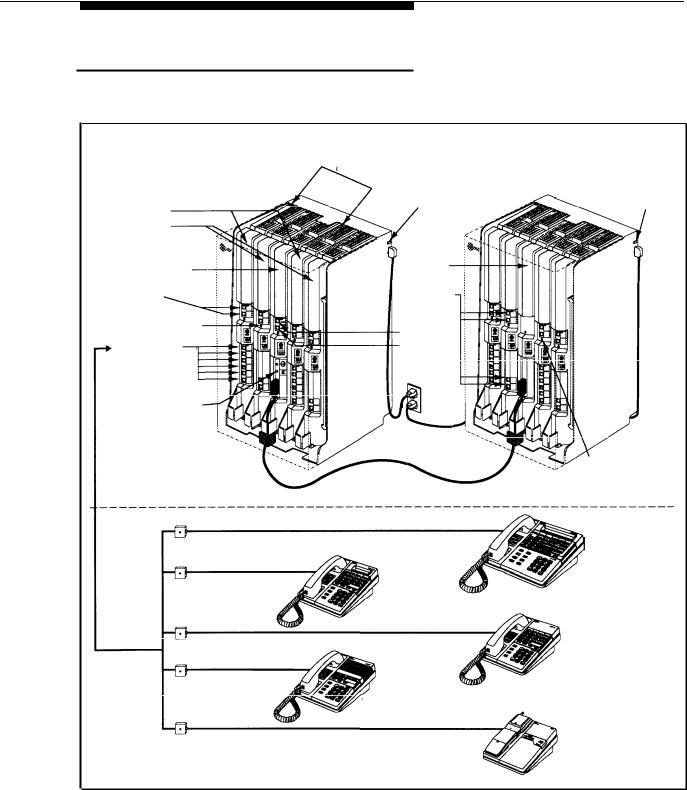
Figure 1-3 shows an equipment controller and MLSand MLC-model telephones connected to it. A brief description of each component follows the figure.
EQUIPMENT CONTROLLER (covers not shown)
|
|
206 Module |
|
|
Primary |
|
Circuit Breakers |
Expansion |
|
|
|
|||
|
|
|
||
Carrier |
|
Main Circuit |
Carrier |
Main Circuit |
206 Modules |
|
Breaker |
|
Breaker |
|
|
|
|
|
400 Modules |
|
|
|
|
Primary |
|
Expansion |
|
|
|
Processor |
|
|
|
Processor Module |
|
Module |
|
|
Line Jacks |
|
Line Jacks |
|
|
Power Indicators |
|
|
|
|
(LEDs) |
|
PAGE Jack |
|
|
|
|
|
|
|
Extension Jacks |
|
SMDR Jack |
|
|
(206 modules only) |
|
|
|
|
MUSIC ON HOLD Jack (for RCA phono plug)
Expansion |
|
Cable |
Power Indicators |
|
(LEDs) |
PHONES
MLS-34D
Display Phone
MLS-12D
Display Phone
MLS-12
Phone
MLS-6
Phone
Wall Jacks
MLC-6
Cordless Phone
Figure 1-3. Equipment Controller and MLS/MLC-Model Telephones
Overview 1-7

Equipment Controller
The equipment controller is the heart of your premises equipment. It is made up of one or two carriers — the plastic housing consisting of the backplane and cover. The backplane distributes power to the premises equipment, and has slots where modules are placed; the cover slides onto the front of the backplane after all the modules have been installed.
The system must have a primary carrier for support of up to 12 lines and extensions, and can be expanded to include an expansion carrier for support of up to 12 more lines and extensions. A fully loaded system has both carriers.
Modules
The following modules are installed in your equipment controller:
■Primary processor module. The primary processor module manages the components of your premises equipment. It has jacks for a music-on-hold audio source, a loudspeaker paging system, and a call reporting device (SMDR), such as a printer. The primary processor module is always installed in the center slot of the primary carrier.
■Expansion processor module. (optional) The expansion processor module extends the primary processor module’s management capabilities to the lines and extensions connected to modules in the expansion carrier. An expansion cable connects the primary processor module to the expansion processor module. This module is always installed in the center slot of the expansion carrier.
■206 Modules. Each 206 module connects a maximum of two Centrex lines and six extensions to the equipment controller. You can connect telephones and other telecommunications devices (such as fax machines, answering machines, or modems) to the extension jacks on the 206 module (either directly or through your building’s extension jacks). Each 206 module has a green power indicator that shows it is receiving power from the equipment controller. At least one 206 module is required in the leftmost slot of the primary carrier.
■400 Module. The 400 module is similar to the 206 module, but without extension jacks. It has jacks for four Centrex lines. The 400 module is always installed to the right of a 206 module.
Capacity
The number of 206 and 400 modules you install in the equipment controller determines the number of available lines and extensions. The controller implements the Centrex requirement of one line for each extension. Therefore, when you install a 400 module (four lines) next to a 206 module (two lines, six extensions) in a carrier, the combined pair provides an equal number (six) of lines and extensions. For the maximum number of lines and extensions in a two-carrier configuration, pair four 206 modules with four 400 modules—for a total of 24 lines and 24 extensions.
1-8 Overview

MLSand MLC-Model Telephones
AT&T MLSand MLC-model telephones are designed to make maximum use of the features provided by your system. The following models are available for use with your system:
■AT&T MLS-34D Telephone. This phone is the best choice for extensions used by the system manager (for equipment programming), receptionist, or operator. It has 32 buttons that can be used for outside lines or programmed for one-touch access to features. It also has a built-in speaker and microphone (for dialing and having a conversation without lifting the handset) and a large character display that shows the following:
■Current date, day, and time
■Number you dialed and elapsed time (when you make a call)
■Prompts and messages.
■AT&T MLS-12D Telephone. This phone has 10 buttons that can be used for outside lines or programmed for one-touch access to features (and 6 more buttons without lights that can only be used for programmable features). It has a built-in speaker and microphone, and a display similar to the one on the MLS-34D telephone.
NOTE:
An MLS-34D or MLS-12D telephone is required for equipment programming. Use the MLS-12D phone only if there are no MLS-34D phones installed at the site.
■AT&T MLS-12 Telephone. This telephone has all the features of the MLS-12D telephone, but without a display.
■AT&T MLS-6 Telephone. This phone has 4 buttons that can be used for outside lines or programmed for one-touch access to features. It also has a built-in speaker, but no microphone. This means that a user can dial a number without lifting the handset, but must lift the handset to speak when the party answers.
■AT&T MLC-6 Cordless Telephone. This cordless telephone works like the MLS-6 corded telephone. It has 4 buttons that can be used for outside lines or programmed for one-touch access to features. It also includes a display that shows line status, an On/Off button that must be pressed before using the phone (to save battery power), and additional feature buttons to support cordless operation (for more information, see
MLC-6 Cordless Telephone Quick Reference: Display and Controls).
Auxiliary Equipment
The premises equipment works with many telecommunications devices, not only MLSand MLC-model telephones. You can connect industry-standard devices to your equipment controller, and certain models of other devices, all without expensive adapters.
Overview 1-9
Industry-Standard Devices
Many industry-standard, single-line telecommunications devices will work with the equipment controller:
■Standard touch-tone, rotary, and cordless telephones (such as those you might have in your home), including feature phones with built-in feature buttons and lights
■Fax machines
■Answering machines
■Modems
■Credit card scanners.
Limitations
You can connect standard devices to your equipment controller, regardless of the manufacturer. The following limitations apply:
■The device must be industry-standard and non-proprietary. That is, it cannot be made specifically for use on a particular telephone system. (For example, you cannot connect an AT&T MERLIN® phone, because it is specifically designed for use on a MERLIN system.)
NOTE:
You can connect a multiple-line device to the equipment controller, but for best results it should be installed and used as if it were a single-line device.
■The device’s Ringer Equivalence Number (REN*) cannot be greater than 2.0. (The REN is shown on a label on the device, usually on the bottom.)
Connecting and Using Standard Devices
You can connect a standard device so that it is on an extension by itself, or so that it shares an extension with another piece of equipment (either another standard device or an MLSor MLC-model phone). An extension with two devices connected to it is called a combination extension. For example, you can connect an MLS-model phone and a standard phone to the same extension, so that the standard phone can be used to place and receive calls in the event of a power failure. To connect two devices on one extension, you need an inexpensive AT&T 267F2 bridging adapter (two are provided with each 206 module).
Chapter 2 explains how to connect standard devices to the equipment controller and how to combine them on a single extension. (See page 2-5 for installation instructions for combination extensions.) For additional information on programming and using fax machines, answering machines, modems, or credit card scanners, see Chapter 7.
*
REN is a measure of the power it takes to ring a phone. A typical home phone line handles 4.0–5.0 RENs; each extension jack in your equipment controller can handle 2.0 RENs.
1-10 Overview

Other Devices
You can connect other devices to your equipment controller, but only specific models are compatible with the equipment controller. (See Appendix C for product ordering information.)
■Call accounting devices and printers allow the system manager to print call reports. The call accounting device or printer connects directly to the primary processor module in the primary carrier. See “Call Reporting Devices (SMDR)” on page 7-7 for more information.
■Doorphones allow visitors to alert up to five extensions at once by pressing a button on the doorphone; the person who answers a doorphone call can then use the phone to speak to the visitor at the doorphone. The equipment controller supports up to two proprietary doorphones, which can be installed indoors or outdoors. A doorphone is especially useful for providing access to offices or departments after hours. For example, you can install a doorphone outside your building entrance to allow visitors to alert telephones inside the building when the receptionist is not there and the front door is locked.
■Loudspeaker paging systems allow you to broadcast a message over a large area, by connecting the paging system directly to the PAGE jack on the primary processor module. The equipment controller supports all AT&T paging systems. For information on how to use a loudspeaker paging system with the equipment controller, see page 6-17.
■Music-on-hold systems allow you to play recorded music to callers while they are on hold, by connecting the music-on-hold system to the primary processor module. The equipment controller supports the AT&T Magic on Hold system and most models from other manufacturers.
■Extra alerts are strobes, lights, chimes, horns, or bells that light or ring when calls come in. For example, you can use an audible alert (chime, horn, or bell) to replace a phone ring in a noisy area, such as a factory. Similarly, you can use a visual alert (strobe or light) to replace a phone ring in a quiet area, such as a library.
■Electromagnetic Interference (EMI) filters allow you to block “noise” generated by a nearby radio station, as well as most electrical devices. The equipment controller supports the AT&T Z300A EMI Filter.
■Uninterruptible Power Supply (UPS) allows full equipment operation during a power failure. The equipment controller supports the AT&T 360VA UPS.
■In-Range Out-of-Building (IROB) protectors are required to prevent electrical surges from damaging your equipment when phones are installed in another building, but on the same continuous property. The equipment controller supports the AT&T IROB protector, which provides coverage over a distance of 3,000 feet for standard phones and 1,000 feet for MLSand MLC-model phones. (For installation instructions, refer to the booklet packaged with the IROB protector.)
Overview 1-11

■Speakerphones provide hands-free two-way operation of a phone without lifting the handset. Combining a speakerphone with an MLS-model phone or a standard phone on an extension in a conference room or office is an inexpensive way for several people at a meeting to conference with other parties. The equipment controller supports the AT&T S203 speakerphone. (MLS-model phones have built-in speakers, but they are designed for individual—not group—use.)
■Repertory dialers allow you to store frequently-used numbers for one-touch dialing (Auto Dialing). If a user needs many Auto Dial numbers, a repertory dialer can be combined on an extension with an MLSor MLC-model phone or standard phone.
■Headsets allow users to hold private, hands-free conversations. A headset is a combination earphone and microphone worn on the head, useful for receptionists, salespeople, or others who need to have their hands free while talking on the phone. AT&T offers several compatible headsets.
■Handsets for the hard-of-hearing are designed for users who need even more amplification than is provided by the volume controls on MLSand MLC-model phones. Although the volume controls on MLSand MLC-model phones significantly reduce the need for an amplified handset, hard-of-hearing users may find that the AT&T K6S handset meets their needs.
1-12 Overview

|
|
2 |
|
Installing the Equipment |
|
|
|
Contents
Important Safety Instructions |
2-ii |
|
■ Additional Safety Instructions for Installation Personnel |
2-ii |
|
Terminology |
2-1 |
|
Installation Guidelines |
2-3 |
|
■ |
Placement of Carriers and Modules |
2-3 |
■ Connection of Telephones and Devices |
2-4 |
|
|
Combination Extensions |
2-5 |
Example Configuration |
2-6 |
|
Installation Procedures |
2-8 |
|
■ |
Required Parts |
2-8 |
■ Installing the Carriers and Modules |
2-9 |
|
■ Connecting Lines and Extensions |
2-10 |
|
■ |
Assembling MLS-Model Telephones |
2-11 |
|
Desk Mounting |
2-11 |
|
Wall Mounting |
2-11 |
■ Connecting and Testing Telephones |
2-12 |
|
■ Connecting Doorphones and Hotline Phones |
2-12 |
|
■ Connecting Paging, Call Reporting (SMDR), and |
|
|
|
Music-on-Hold Devices |
2-13 |
Equipment Upgrades |
2-14 |
|
■ |
Adding New Modules |
2-14 |
■ |
Replacing a Module |
2-14 |
Installing the Equipment 2-i

Important Safety Instructions
Always follow these basic safety precautions when using the premises equipment:
1.Read and understand all instructions.
2.Follow all warnings and instructions marked on the product.
3.DO NOT block or cover the ventilation slots and openings. They prevent the product from overheating. DO NOT place the product in a separate enclosure, unless proper ventilation is provided.
4.Never spill liquid on the product or drop objects into the ventilation slots and openings. Doing so may result in serious damage to the components.
5.Repair or service must be performed by a qualified repair person.
6.The product is provided with a three-wire grounding type plug. This is a safety feature. DO NOT defeat the safety purpose of the grounding type plug. DO NOT staple or otherwise attach the AC power supply cord to building surfaces.
7.DO NOT use the product near water or in a wet or damp place (such as a wet basement).
Additional Safety Instructions
for Installation Personnel
1 . DO NOT install telephone wiring during a lightning storm.
2 . DO NOT install telephone jacks in a wet location unless the jack is specifically designed for wet locations.
3 . Never touch uninsulated telephone wires or terminals, unless the telephone line has been disconnected at the network interface.
4 . Use caution when installing or modifying telephone lines.
5 . The equipment carriers must be securely wall mounted.
CAUTION:
If any wiring from the extension jacks leaves the building premises, you must install AT&T IROB protectors (see “Requirements for Out-of-Building Extensions,” page D-2).
CAUTION:
Use only AT&T-manufactured modules in the equipment controller.
CAUTION:
Environmental and electrical conditions must meet the specifications in Appendix D.
SAVE THESE INSTRUCTIONS
2-ii Installing the Equipment

|
|
2 |
|
Installing the Equipment |
|
|
|
This chapter explains how to install the premises equipment. It begins with general guidelines to consider before installation, followed by an example configuration. It ends with step-by-step instructions for connecting and testing the components.
IMPORTANT:
Before installation you should review Forms A and B of the System Planner to identify the type of equipment that should be connected to the extension jacks for your system.
Terminology
The following terms are used in this chapter. In addition, you may wish to review the “Terminology” section of “About This Guide, ” which defines basic terms used throughout this guide, or the Glossary, which defines all terms.
Backplane |
The bottom and rear portion of the plastic housing that makes |
|
up a carrier. The backplane distributes power to the |
|
premises equipment, and has slots where the modules are |
|
installed. |
Carrier |
Molded plastic housing, made up of a backplane and cover, |
|
which holds the equipment controller modules. Your |
|
configuration contains at least the primary carrier and can be |
|
expanded to include an expansion carrier. |
Combination |
An extension that has two devices connected to it using a |
extension |
special connector called a bridging adapter. Combination |
|
extensions can connect two industry-standard devices or an |
|
industry-standard device and an MLSor MLC-model phone, |
|
but not two MLSor MLC-model phones. |
Installing the Equipment 2-1

Equipment The AT&T product that you purchased as part of your Controller system. This product consists of a group of modules that
connect Centrex lines coming into your building to the extensions in your system. The equipment controller also provides equipment features.
Expansion The optional component of the AT&T equipment controller carrier that can be connected to the primary carrier to expand your
system’s line and extension capacity. See also Primary carrier.
Expansion The main module of the expansion carrier, which must be processor installed in the center slot of the expansion carrier. This module AT&T module extends the primary carrier’s management
capabilities to the 206 and 400 modules installed in the expansion carrier. See also Primary processor module.
Extension jack The location on 206 modules that allows you to connect phones (or other telecommunications devices) to the equipment controller.
Extension jack number
400 Module
The number assigned to each extension jack on a 206 module. Extension jack numbers run consecutively from 10 through 33 (for a two-carrier configuration).
The AT&T equipment component that contains jacks for connecting up to four Centrex lines to the equipment controller.
Line jack |
The location on 206 and 400 modules that allows you to |
|
connect Centrex lines to the equipment controller. |
Line jack |
The number assigned to each line jack on a 206 or 400 |
number |
module. Line jack numbers run consecutively from 01 |
|
through 24 (for a two-carrier configuration). |
Network |
A jack, generally located in your equipment room, that |
interface jack |
provides access to a Centrex line coming into your building |
|
from your local telephone company. A telephone cord from |
|
the network interface jack to a line jack on a 206 or 400 |
|
module connects the Centrex line to your system. |
Premises equipment
Primary carrier
The AT&T equipment controller and MLSand MLC-model telephones that you purchased as part of your system, plus all other telecommunications devices that are connected to your equipment controller. For purposes of this guide, premises equipment does not include any equipment that connects directly to Centrex lines without going through the equipment controller.
The required component of the AT&T equipment controller that contains the primary processor module and up to two 206 and two 400 modules. This provides for connection of up to 12 lines and 12 extensions. See also Expansion carrier.
2-2 Installing the Equipment

|
|
|
|
|
Primary |
This AT&T module, which is always installed in the center slot |
|
|
processor |
of the primary carrier, manages the components of your |
|
|
module |
premises equipment. See also Expansion processor module. |
|
|
206 Module |
The AT&T equipment component that contains jacks for |
|
|
|
connecting up to two Centrex lines and up to six extensions |
|
|
|
to the equipment controller. |
|
Installation Guidelines
In this chapter, we refer to line jacks and extension jacks; these terms describe the locations where connections are made to the equipment controller. During installation, each Centrex line is connected to a line jack on the controller. In addition, each phone (or optional device) is connected to an extension jack on the controller (either directly or via a wall jack). Once connections are made, the controller associates each line jack (numbered consecutively from 01 through 24) with a specific extension jack (numbered consecutively from 10 through 33). Each Centrex line is the primary line for the phone at the corresponding extension. (Refer to Form B in the System Planner, which records how your phone numbers are assigned to system extensions.)
Placement of Carriers and Modules
■Carriers. You will be installing either one or two carriers, depending on the number of lines you have (see “Capacity,” on page 1-8).If you are going to install the expansion carrier, plan to install it to the right of the primary carrier. Install the backplane(s) within five feet of the network interface jacks and a grounded 110 VAC electrical outlet not controlled by a switch. If you are installing two carriers, both must be plugged into the same power outlet. In addition, when you mount the backplane(s) on the wall, leave at least six inches of clearance at the top and sides, and two feet at the front and bottom.
■Modules. To install modules, follow the rules below:
■Install the primary processor module in the center slot of the primary carrier.
■If you are installing the expansion carrier, install the expansion processor module in its center slot.
■The first (leftmost) slot in each carrier must contain a 206 module.
■Do not skip slots when installing 206 and 400 modules.
■A 400 module must be installed to the right of each 206 module (except the last 400 module, which can be skipped if you do not need the additional lines).
■If a second 206 module is installed in a carrier, it must be installed to the right of the processor module.
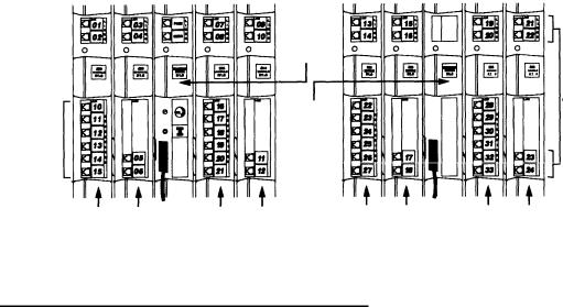
Figure 2-1 shows the two carriers, with line and extension jacks numbered, for a configuration containing 24 lines and 24 extensions. For a detailed explanation of line and extension jack numbering, see Chapter 3.
Installing the Equipment 2-3
|
|
|
|
|
|
|
|
|
|
|
|
|
|
|
|
|
|
|
|
|
|
|
|
|
|
Primary |
|
|
|
|
|
|
|
Expansion |
|
|
|
Carrier |
|
|
|
Primary |
|
|
Carrier |
|
|
|
|
|
|
|
|
Processor |
|
|
|
|
|
|
|
|
|
|
|
Module |
|
|
|
|
|
|
|
|
|
|
|
|
|
|
|
Line |
|
|
|
|
|
|
|
Expansion |
|
|
Jacks |
|
|
|
|
|
|
|
|
|
|
|
|
||
|
|
|
|
|
|
Processor |
|
|
|
|
|
|
|
Extension |
|
|
|
Module |
|
|
|
|
|
|
|
Jacks |
|
|
|
|
|
|
|
|
|
|
|
206 |
4 0 0 |
2 0 6 |
4 0 0 |
206 |
4 0 0 |
2 0 6 |
400 |
|
|
|
|
|
|
|
|
|
|
|
|
|
|
Figure 2-1. Line and Extension Numbering at the Equipment Controller
Connection of Telephones and Devices
You can connect the following telephones and devices to the equipment controller:
■MLSand MLC-Model Phones. MLSand MLC-model phones require at least two-pair wiring and are compatible with AT&T four-pair SYSTIMAX™ wiring. If you need a shorter cord for wall mounting, use AT&T’s two-foot D4BU-29 mounting cord (available separately—see page C-12). An MLS-34D phone connected to extension jack 10 or 11 is used for System Programming. Use an MLS-12D phone for System Programming only if there are no MLS-34D phones installed at your business site.
■Industry-Standard Devices. Industry-standard equipment (including standard phones) require one-pair mounting cords; AT&T D2R mounting cords are recommended.
■Standard Phones. Connect standard touch-tone or rotary phones to the equipment controller for:
—Power Failure Operation. During a power failure, MLS and MLC-model phones will not work because they require power to operate. However, if standard phones are connected to extension jacks 10, 16, 22, or 28, they can place and answer calls on lines at line jacks 01, 07, 13, or 19, respectively. Connect a standard phone to one or more of these extensions, either alone or combined with an MLSor MLC-model phone. (If you combine a standard phone and an MLSor MLC-model phone on one extension, you may want to turn off the standard phone’s ringer during normal use.)
2-4 Installing the Equipment

Hotline Phones. A Hotline phone should be a standard phone—not an MLS or MLC-model phone—but can ring any type of phone. You can specify one alert extension for each Hotline phone, and you can install multiple Hotline phones, if you wish. A Hotline phone only requires connection to an available extension jack (with no Centrex line assigned to the extension). To simplify programming, we recommend installing Hotline phones and doorphones on the last available extension jacks on the last
installed 206 module in the equipment controller (if the last module in the equipment controller is a 206 module with no corresponding 400 module, the last four extension jacks will not have Centrex lines assigned to them by default).
■Auxiliary Equipment. There area variety of ways to set up fax machines, modems, and answering machines to work with the equipment controller. See Chapter 7 for advice on using this equipment. To connect a telephone and a fax on the same extension, see “Combination Extensions” below.
■Doorphones. You can connect up to two proprietary doorphones to the equipment controller. Like Hotline phones, doorphones only require connection to an available extension jack (with no Centrex line assigned to the extension). To simplify programming, we recommend installing doorphones and Hotline phones on the last available extension jacks on the last installed 206 module in the equipment controller (if the last module in the equipment controller is a 206 module with no corresponding 400 module, the last four extension jacks will not have Centrex lines assigned to them by default).
■Call Reporting Devices. You can connect a call accounting device to the SMDR jack on the primary processor module for recording call activity. (See “Call Reporting Devices (SMDR)” on page 7-7 for more information.)
■In-Range Out-of-Building Protectors. Installing phones in a different building from the equipment controller requires AT&T In-Range Out-of-Building (IROB) protectors, to prevent damage due to lightning (installation instructions are included with the protector).
Combination Extensions
You can connect a standard device (such as a standard phone or a fax machine) on an extension by itself, or you can use an AT&T 267F2 bridging adapter (only) to combine the standard device with another standard device or an MLSor MLC-model phone at one extension jack. You cannot install two MLSor MLC-model phones on the same extension, and the combined REN of two devices on an extension must be no more than 2.0. Figure 2-2 shows how to connect the two devices to the bridging adapter at a combination extension,
AT&T
267F2 Adapter
Standard Device Only
System Phone or Standard Device
Wall Jack
Figure 2-2. Connecting Two Devices on One Extension
Installing the Equipment 2-5
Loading...