


Operating Instructions
COOKER
|
|
|
|
|
|
Contents |
|
|
|
|
|
|
Installation, 2-3 |
GB |
|
FR |
|
RO |
|
|
|
|
|
Electrical connections |
|||
|
|
|
|
|
|
Gas connection |
|
|
|
|
|
|
|
English, 1 |
Français, 10 |
Românã, 22 |
Table of burner and nozzle specifications |
|||
|
|
|
|
|
|
Technical data |
GB
AR
AR
C 34S G1 EX
Description of the appliance, 4
Overall view Control panel
Start-up and use, 5-7
Using the hob
Using the oven
Oven cooking advice table
Precautions and tips, 8
General safety Disposal
Respecting and conserving the environment
Maintenance and care, 9
Switching the appliance off
Cleaning the appliance
Gas tap maintenance
Replacing the oven light bulb
Assistance
Installation
|
! Before operating your new appliance please read |
|
GB |
||
this instruction booklet carefully. It contains |
||
|
important information concerning the safe installation |
|
|
||
AR |
and operation of the appliance. |
|
! Please keep these operating instructions for future |
||
|
||
|
reference. Make sure that the instructions are kept |
|
|
with the appliance if it is sold, given away or moved. |
|
|
! The appliance must be installed by a qualified |
|
|
professional according to the instructions provided. |
|
|
! Any necessary adjustment or maintenance must be |
|
|
performed after the cooker has been disconnected |
|
|
from the electricity supply. |
Levelling |
If it is necessary to level the appliance, screw the adjustable feet into the places provided on each corner of the base of the cooker (see figure).
The legs* fit into the slots on the underside of the base of the cooker.
Electrical connection
Install a standardised plug corresponding to the load indicated on the appliance data plate (see Technical data table).
The appliance must be directly connected to the mains using an omnipolar circuit-breaker with a minimum contact opening of 3 mm installed between the appliance and the mains. The circuit-breaker must be suitable for the charge indicated and must comply with NFC 15-100 regulations (the earthing wire must not be interrupted by the circuit-breaker). The supply cable must be positioned so that it does not come into contact with temperatures higher than 50°C at any point.
Before connecting the appliance to the power supply, make sure that:
•The appliance is earthed and the plug is compliant with the law.
•The socket can withstand the maximum power of the appliance, which is indicated by the data plate.
•The voltage is in the range between the values indicated on the data plate.
•The socket is compatible with the plug of the appliance. If the socket is incompatible with the
plug, ask an authorised technician to replace it. Do not use extension cords or multiple sockets.
!Once the appliance has been installed, the power supply cable and the electrical socket must be easily accessible.
!The cable must not be bent or compressed.
!The cable must be checked regularly and replaced by authorised technicians only.
!The manufacturer declines any liability should these safety measures not be observed.
Installation of the cooker
The appliance can be installed next to cabinets, provided the height does not exceed that of the hob. If the cooker is placed touching walls or sides of neighbouring cabinets, these must be capable of withstanding a temperature rise of 50°C above room temperature. For a correct installation of the cooker the following precautions must be followed:
•The furniture units next to the cooker, that is higher than the working boards, must be placed at least 600 mm from the edge of the board. Curtains must not be fitted immediately behind the cooker or within 600 mm. of the sides of the cooker.
Connecting the gas
The appliance should be connected to a gas cylinder in compliance with current directives. On some models the gas supply can be connected on the left or on the right, as necessary; to change the connection, reverse the position of the hose holder with that of the cap and replace replace the gasket (supplied with the appliance). Remember to install a pressure regulator on the LPG cylinder, which complies with current directive.
! Check that the supply pressure complies with the values indicated in table 1 “Characteristics of the burners and nozzles” since this will ensure safe operation, correct consumption and ensure a longer life to your appliance.
* Only available in certain models
2
Connection with hose
Make the connection using a gas hose complying with the the characteristics provided in current directive. The internal diameter of the pipe used is as follows:
- 8mm for liquid gas;
When installing the hose, remember to take the following precautions:
Check that the hose fits firmly into place at the two ends and fix it with clamps complying to current
directive.If any of the above recommendations can not be adopted, flexible metal pipes should be used.
Tight control
When installation has been completed, check the pipe fitting for leaks with a soapy solution. Never use a flame. Once the connection has been made, ensure that the flexible metal tube does not touch any moving parts and is not crushed.
Table of burner and nozzle specifications
|
|
|
|
|
|
|
|
|
|
|
|
|
|
|
|
|
|
|
|
|
|
|
|
|
|
|
|
|
|
|
|
|
|
|
|
|
|
|
|
|
|
|
|
||||
|
|
|
|
|
|
|
|
|
|
|
|
|
!! |
|
" |
|
|
|
|||||
|
|
|
|
|
|
|
|
|
|
|
|
|
|
|
|
#$ |
" |
' |
|
|
|
|
!" |
% & # |
|
|
|||||
|
|
|
|
|
|
|
|
|
|
|
|
|
|
|
|
( ) |
" |
' |
"! |
|
*" |
|
!" |
# ( |
|
|
|||||
|
|
|
|
|
|
|
|
|
|
|
|
|
|
|
|
+, |
|
* |
" |
|
!!" |
|
*" |
|
|
|
|
|
|
|
|
- |
|
|
|
|
" |
|
|
|
|
|
|
|
|
|
|
# .. |
|
$/ |
|
|
|
' |
|
|
%$/ |
|
|
|
!" |
|
|
|
|
|
|
|
|
||
|
% )$/ |
|
|
|
'" |
|
|
|
|
|
|
|
|
||
|
|
|
|
|
|
|
|
S S
A R
C 34S G1 EX
TECHNICAL DATA
Oven dimensions |
34x39x44 cm |
|
(HxWxD) |
|
|
Volume |
58 l |
|
Useful |
|
|
measurements |
width 42 cm |
|
relating to the |
||
depth 44 cm |
||
oven |
||
height 17 cm |
||
compartment |
||
|
||
Burners |
may be adapted for use with any |
|
type of gas shown on the data |
||
|
plate. |
|
|
EC Directives: 2006/95/CE dated |
|
|
12.12.06 (Low Voltage) and |
|
|
subsequent amendments - |
|
|
2004/108/CE dated 15/12/04 |
|
|
(Electromagnetic Compatibility) |
|
|
and subsequent amendments - |
|
|
2009/142/EC dated 30/11/09 (Gas) |
|
|
and subsequent amendments - |
|
|
93/68/EEC dated 22/07/93 and |
|
|
subsequent amendments - |
|
|
2002/96/EC. |
|
|
1275/2008 (Stand-by/Off mode) |
GB
AR
3
 EX User Manual")
Descriptionof the appliance
Overall view
GB
Glass cover*
AR
Gas burner |
Containment |
|
Hob grid |
surface for spills |
|
Control panel |
GUIDE RAILS |
|
|
for the sliding racks |
|
|
position 5 |
|
GRILL rack |
position 4 |
|
DRIPPING PAN |
position 3 |
|
position 2 |
||
|
||
|
position 1 |
|
Adjustable foot |
Adjustable foot |
|
|
Control panel
|
TIMER |
|
OVEN |
Hob BURNER |
|||||
|
knob* |
|
control knob |
control knobs |
|||||
|
|
|
|
|
|
|
|
|
|
|
|
|
|
|
|
|
|
|
|
|
|
|
|
|
|
|
|
|
|
|
|
|
|
|
|
|
|
|
|
OVEN LIGHT and
ROTISSERIE button
GAS BURNER
ignition button*
* Only available in certain models.
WARNING! The glass lid can break in if it is heated up. Turn off all the burners and the electric plates before closing the lid. *Applies to the models with glass cover only.
4
Start-up and use
Using the hob
Lighting the burners
For each BURNER knob there is a complete ring showing the strength of the flame for the relevant burner.
To light one of the burners on the hob:
1.Bring a flame or gas lighter close to the burner.
2.Press the BURNER knob and turn it in an anticlockwise direction so that it is pointing to the maximum flame setting E.
3.Adjust the intensity of the flame to the desired level by turning the BURNER knob in an anticlockwise direction. This may be the minimum setting C, the maximum setting E or any position in between the two.
|
If the appliance is fitted with |
|
X |
an electronic lighting |
|
device*(D) (see figure), |
||
|
||
|
press the ignition button, |
|
|
marked with the symbol |
|
D |
1, then hold the BURNER |
knob down and turn it in an anticlockwise direction, towards the maximum flame setting, until the burner is lit.The burner may be extinguished when the knob is released. If this occurs, repeat the operation, holding the knob down for a longer period of time.
! If the flame is accidentally extinguished, switch off the burner and wait for at least 1 minute before attempting to relight it.
If the appliance is equipped with a flame failure safety device*(X), press and hold the BURNER knob for approximately 3-7 seconds to keep the flame alight and to activate the device.
To switch the burner off, turn the knob until it reaches the stop position •.
Practical advice on using the burners
For the burners to work in the most efficient way possible and to save on the amount of gas consumed, it is recommended that only pans that have a lid and a flat base are used. They should also be suited to the size of the burner.
* Only available in certain models.
|
|
|
|
$ |
$ $ |
|
|
$ $ |
$ $ |
|
|
$ |
$ $ |
|
|
To identify the type of burner, please refer to the diagrams contained in the “Burner and nozzle specifications”.
Using the oven
!The first time you use your appliance, heat the empty oven with its door closed at its maximum temperature for at least half an hour. Ensure that the room is well ventilated before switching the oven off and opening the oven door. The appliance may emit a slightly unpleasant odour caused by protective substances used during the manufacturing process burning away.
!Never put objects directly on the bottom of the oven; this will avoid the enamel coating being damaged. Only use position 1 in the oven when cooking with the rotisserie spit.
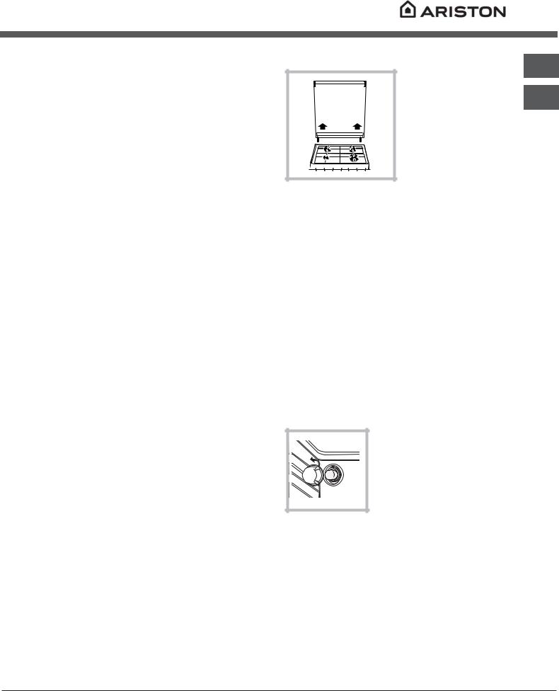
Lighting the oven
To light the oven burner, bring a flame or gas lighter close to opening F (see figure) and press the OVEN control knob while turning it in an anticlockwise direction until it reaches the MAX position.
If, after 15 seconds, the burner is still not alight, release the knob, open the oven door and wait for at least 1 minute before trying to light it again.
!The oven is fitted with a safety device and it is therefore necessary to hold the OVEN control knob down for approximately 6 seconds.
!If the flame is accidentally extinguished, switch off the burner and wait for at least 1 minute before attempting to relight the oven.
Adjusting the temperature
To set the desired cooking temperature, turn the OVEN control knob in an anticlockwise direction. Temperatures are displayed on the control panel and may vary between MIN (140°C) and MAX (250°C).
GB
AR
5
|
Once the set temperature has been reached, the |
|
GB |
||
oven will keep it constant by using its thermostat. |
||
|
Grill |
|
|
||
AR |
||
|
||
|
To light the grill, bring a flame or gas lighter close to |
|
|
||
|
the burner and press the OVEN control knob while |
|
|
turning it in a clockwise direction until it reaches the |
|
|
d position. The grill enables the surface of food to |
|
|
be browned evenly and is particularly suitable for |
|
|
roast dishes, schnitzel and sausages. Place the |
|
|
rack in position 4 or 5 and the dripping pan in |
|
|
position 1 to collect fat and prevent the formation of |
|
|
smoke. |
|
|
! The grill is fitted with a safety device and it is |
|
|
therefore necessary to hold the OVEN control knob |
|
|
down for approximately 6 seconds. |
|
|
! If the flame is accidentally extinguished, switch off |
|
|
the burner and wait for at least 1 minute before |
|
|
attempting to relight the grill. |
D |
! When using the grill, leave the oven door ajar, positioning the deflector D between the door and the control panel (see figure) in order to prevent the knobs from overheating.
Turnspit |
To operate the rotisserie (see diagram) proceed as follows:
1.Place the dripping pan in position 1.
2.Place the rotisserie support in position 4 and insert the spit in the hole provided on the back panel of the oven.
3. Acitvate the function by pressing the TURNSPIT button.
Oven light
The light may be switched on at any moment by pressing the OVEN LIGHT button.
Timer*
To activate the Timer proceed as follows:
1.Turn the TIMER knob in a clockwise direction 4 for almost one complete revolution to set the buzzer.
2.Turn the TIMER knob in an anticlockwise direction 5 to set the desired length of time.
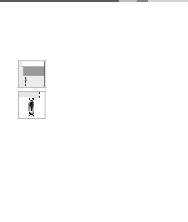
Lower compartment*
There is a compartment underneath the oven that may be used to store oven accessories or deep dishes. To open the door pull it downwards (see figure).
! Do not place flammable materials in the lower oven compartment.
A
S 
In gas cooker models, there is a sliding protection layer A that shields the lower compartment from the heat generated by the burner (see figure).
To remove the sliding protection remove the screw S (see figure). To replace it, lock it in place with the screw S.
! Before using the oven make sure that the sliding protection is fixed correctly.
* Only available in certain models.
6
Oven cooking advice table
Foods |
Weight (in |
Rack |
Preheating time (min) |
Recommended |
Cooking time |
|
kg) |
position |
|
Temperature (°C) |
(minutes) |
Pasta |
|
|
|
|
|
Lasagne |
2.5 |
3 |
10 |
210 |
60-75 |
Cannelloni |
2.5 |
3 |
10 |
200 |
40-50 |
Gratin dishes |
2.5 |
3 |
10 |
200 |
40-50 |
Meat |
|
3 |
10 |
200 |
85-90 |
Veal |
1.7 |
||||
Chicken |
1.5 |
3 |
10 |
220 |
90-100 |
Duck |
1.8 |
3 |
10 |
200 |
100-110 |
Rabbit |
2 |
3 |
10 |
200 |
70-80 |
Pork |
2.1 |
3 |
10 |
200 |
70-80 |
Lamb |
1.8 |
3 |
10 |
200 |
90-95 |
Fish |
|
|
|
|
|
Mackerel |
1.1 |
3 |
10 |
180-200 |
35-40 |
Dentex |
1.5 |
3 |
10 |
180-200 |
40-50 |
Trout baked in foil |
1 |
3 |
10 |
180-200 |
40-45 |
Pizza |
|
|
|
|
|
Neapolitan-style |
1 |
3 |
15 |
220 |
15-20 |
Pies |
|
3 |
15 |
180 |
30-35 |
Biscuits |
0.5 |
||||
Tart |
1.1 |
3 |
15 |
180 |
30-35 |
Savoury pies |
1 |
3 |
15 |
180 |
45-50 |
Leavened cakes |
1 |
3 |
15 |
180 |
35-40 |
Grilled foods |
|
4 |
5 |
|
15-20 |
Veal steak |
1 |
|
|||
Cutlets |
1.5 |
4 |
5 |
|
20 |
Hamburgers |
1 |
3 |
5 |
|
20-30 |
Mackerel |
1 |
4 |
5 |
|
15-20 |
Toast |
4 pcs |
4 |
5 |
|
4-5 |
Grilling using the rotisserie |
|
|
|
|
|
Spit-roast veal |
1 |
- |
5 |
|
70-80 |
Spit-roast chicken |
2 |
- |
5 |
|
70-80 |
Grilling using the multi-spit rotisserie* |
|
|
|
|
|
Meat kebabs |
1 |
- |
5 |
|
40-45 |
Vegetable kebabs |
0.8 |
- |
5 |
|
25-30 |
GB
AR
* Only available in certain models.
7

Precautions and tips
|
! This appliance has been designed and |
|
GB |
||
manufactured in compliance with international safety |
||
|
standards. |
|
|
||
AR |
The following warnings are provided for safety |
|
reasons and must be read carefully. |
||
|
||
|
|
General safety
•These instructions are only valid for the countries whose symbols appear in the manual and on the serial number plate.
•The appliance was designed for domestic use inside the home and is not intended for commercial or industrial use.
•The appliance must not be installed outdoors, even in covered areas. It is extremely dangerous to leave the appliance exposed to rain and storms.
•Do not touch the appliance with bare feet or with wet or damp hands and feet.
•The appliance must be used by adults only for the preparation of food, in accordance with the instructions outlined in this booklet. Any other use of the appliance (e.g. for heating the room) constitutes improper use and is dangerous.
The manufacturer may not be held liable for any damage resulting from improper, incorrect and unreasonable use of the appliance.
•Keep children away from the oven.
•Make sure that the power supply cables of other electrical appliances do not come into contact with the hot parts of the oven.
•The openings used for the ventilation and dispersion of heat must never be covered.
•Do not close the glass hob cover (selected models only) when the burners are alight or when they are still hot.
•Always use oven gloves when placing cookware in the oven or when removing it.
•Do not use flammable liquids (alcohol, petrol, etc...) near the appliance while it is in use.
•Do not place flammable material in the lower storage compartment or in the oven itself. If the appliance is switched on accidentally, it could catch fire.
•Always make sure the knobs are in the • position and that the gas tap is closed when the appliance is not in use.
•When unplugging the appliance, always pull the plug from the mains socket; do not pull on the cable.
•Never perform any cleaning or maintenance work without having disconnected the appliance from the electricity mains.
•If the appliance breaks down, under no circumstances should you attempt to repair the appliance yourself. Repairs carried out by inexperienced persons may cause injury or further malfunctioning of the appliance. Contact Assistance.
•Do not rest heavy objects on the open oven door.
•The appliance must be used by adults only for the preparation of food, in accordance with the instructions outlined in this booklet. Any other use of the appliance (e.g. for heating the room) constitutes improper use and is dangerous. The manufacturer may not be held liable for any damage resulting from improper, incorrect and unreasonable use of the appliance.
Disposal
•When disposing of packaging material: observe local legislation so that the packaging may be reused.
•When disposing of your old appliance: contact your Local Authority and make use of the official refuse collection body responsible for your area.
Respecting and conserving the environment
•You can help to reduce the peak load of the electricity supply network companies by using the oven in the hours between late afternoon and the early hours of the morning.
•Check the door seals regularly and wipe them clean to ensure they are free of debris so that they adhere properly to the door, thus avoiding heat dispersion.
8
Care and maintenance
Switching the appliance off
Disconnect your appliance from the electricity supply before carrying out any work on it.
Cleaning the appliance
!Do not use abrasive or corrosive detergents such as stain removers, anti-rust products, powder detergents or sponges with abrasive surfaces: these may scratch the surface beyond repair.
!Never use steam cleaners or pressure cleaners on the appliance.
•It is usually sufficient simply to wash the hob using a damp sponge and dry it with absorbent kitchen roll.
•The stainless steel or enamel-coated external parts and the rubber seals may be cleaned using a sponge that has been soaked in lukewarm water and neutral soap. Use specialised products for the removal of stubborn stains. After cleaning, rinse well and dry thoroughly. Do not use abrasive powders or corrosive substances.
•The hob grids, burner caps, flame spreader rings and the hob burners can be removed
to make cleaning easier; wash them in hot water and non-abrasive detergent, making sure all burnt-on residue is removed before drying them thoroughly.
•For hobs with electronic ignition, the terminal part of the electronic lighting devices should be cleaned frequently and the gas outlet holes should be checked for blockages.
•The inside of the oven should ideally be cleaned after each use, while it is still lukewarm. Use hot water and detergent, then rinse well and dry with a soft cloth. Do not use abrasive products.
•Clean the glass oven door using non-abrasive products and sponges and dry it with a soft cloth.
•The accessories can be washed like everyday crockery, and are even dishwasher safe.
•Stainless steel can be marked by hard water that has been left on the surface for a long time, or by aggressive detergents containing phosphorus.
After cleaning, rinse well and dry thoroughly. Any remaining drops of water should also be dried.
!Do not close the cover when the burners are alight or when they are still hot.
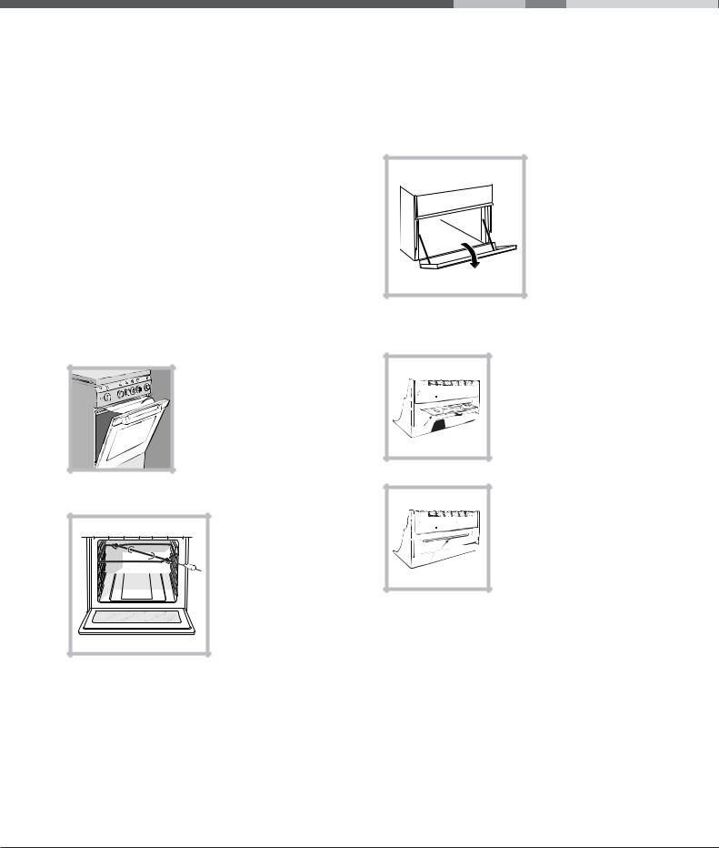
The cover
GB
If the cooker is fitted with a glass cover, this cover
should be cleaned using AR lukewarm water. Do not
use abrasive products. It is possible to remove
the cover in order to make cleaning the area
behind the hob easier.
Open the cover fully and pull it upwards (see figure).
! Do not close the cover when the burners are alight or when they are still hot.
Inspecting the oven seals
Check the door seals around the oven periodically. If the seals are damaged, please contact your nearest Authorised After-sales Service Centre. We recommend that the oven is not used until the seals have been replaced.
Gas tap maintenance
Over time, the taps may become jammed or difficult to turn. If this occurs, the tap must be replaced.
! This procedure must be performed by a qualified technician who has been authorised by the manufacturer.
Replacing the oven light bulb
1. After disconnecting the oven from the electricity mains, remove the glass lid covering
the lamp socket (see figure).
2. Remove the light bulb and replace it with a similar one:
voltage 230 V, wattage 25 W, cap E 14.
3. Replace the lid and reconnect the oven to the electricity supply.
Assistance
Please have the following information handy:
•The appliance model (Mod.).
•The serial number (S/N).
This information can be found on the data plate located on the appliance and/or on the packaging.
9
Mode d’emploi
FR
GB |
|
FR |
|
RO |
|
|
|
|
|
|
|
|
|
Français, 10 |
|
|
|
English, 1 |
Românã, 22 |
||||
AR
C 34S G1 EX
CUISINIERE
Sommaire
Installation, 11-15
Positionnement et nivellement Raccordement électrique Raccordement gaz
Adaptation aux différents types de gaz Caractéristiques techniques
Tableau Caractéristiques des brûleurs et des injecteurs
Description de l’appareil, 16
Vue d’ensemble
Tableau de bord
Mise en marche et utilisation, 17-19
Utilisation du plan de cuisson Utilisation du four
Tableau de cuisson
Précautions et conseils, 20
Sécurité générale
Mise au rebut
Economies et respect de l’environnement
Nettoyage et entretien, 21
Mise hors tension Nettoyage de l’appareil Entretien robinets gaz
Remplacement de l’ampoule d’éclairage du four Assistance
Installation
!Conservez ce mode d’emploi pour pouvoir le consulter à tout moment. En cas de vente, de cession ou de déménagement, veillez à ce qu’il suive l’appareil.
!Lisez attentivement les instructions : elles contiennent des conseils importants sur l’installation, l’utilisation et la sécurité de votre appareil.
!L’installation de l’appareil doit être effectuée par un professionnel du secteur conformément aux instructions du fabricant.
!N’importe quelle opération de réglage, d’entretien, etc., doit être effectuée après avoir débranché la prise de la cuisinière.
Conditions réglementaires d’installation
Le raccordement gaz devra être fait par un professionnel qualifié qui assurera la bonne alimentation en gaz et le meilleur réglage de la combustion des brûleurs. Ces opérations d’installation, quoique simples, sont délicates et primordiales pour que votre cuisinière vous rende le meilleur service. L’installation doit être effectuée conformément aux textes réglementaires et règles de l’art en vigueur, notamment:
•Arrêté du 2 août 1977. Règles techniques et de sécurité applicables aux installations de gaz combustibles et d’hydro-carbures liquéfiés situées à l’intérieur des bâtiments d’habitation et de leur dépendances.
•Norme DTU P45-204. Installations de gaz (anciennement DTU n° 61-1-installations de gaz - Avril 1982 + additif n°1 Juillet 1984).
•Règlement sanitaire départemental.
Aération des locaux
L’appareil doit être installé dans des locaux qui sont aérés en permanence, selon les prescriptions des Normes en vigueur dans le pays d’installation. Il est indispensable que la pièce où l’appareil est installé dispose d’une quantité d’air égale à la quantité d’air comburant nécessaire à une bonne combustion du gaz (le flux d’air doit être d’au moins 3 m3/h par kW de puissance installée).
Les prises d’air, protégées par des grilles, doivent disposer d’un conduit d’au moins 2 cm2 de section utile et dans une position qui leur évite tout risque d’être bouchées accidentellement, même partiellement (voir figure A).
Ces ouvertures doivent être agrandies de 100% (surface minimale 2 cm2) en cas d’appareils dépourvus du dispositif de sécurité de flamme et quand l’afflux de l’air provient de manière indirecte de
pièces voisines (voir figure B) – à condition qu’il ne
s’agisse pas de parties communes du bâtiment, de FR chambres à coucher ou de locaux à risque d’incendie
– équipées d’un conduit d’aération avec l’extérieur comme décrit plus haut.
Local adjacent |
|
|
|
|
|
|
|
|
Local à ventiler |
||||
A |
|
|
|
|
|
B |
|||||||
|
|
|
|
|
|
|
|
|
|
|
|
|
|
|
|
|
|
|
|
|
|
|
|
|
|
|
|
|
|
|
|
|
|
|
|
|
|
|
|
|
|
|
|
|
|
|
|
|
|
|
|
|
|
|
|
|
|
|
|
|
|
|
|
|
|
|
|
|
|
|
|
|
|
|
|
|
|
|
|
|
|
|
|
|
|
|
|
|
|
|
|
|
|
|
|
|
|
A
|
|
|
|
|
|
|
|
|
|
|
|
|
|
|
|
|
|
|
|
|
|
|
|
Ouverture de ventilation |
Agrandissement de la |
||||||
pour l’air comburant |
fissure entre la porte et |
||||||
|
|
|
|
|
le sol |
||
! Après une utilisation prolongée de l’appareil, il est conseillé d’ouvrir une fenêtre ou d’augmenter la vitesse de ventilateurs éventuels.
Evacuation des fumées de combustion
La pièce doit prévoir un système d’évacuation vers l’extérieur des fumées de combustion réalisé au moyen d’une hotte reliée à une cheminée à tirage naturel ou par ventilateur électrique qui entre automatiquement en fonction dès qu’on allume l’appareil (voir figures).
|
|
|
|
|
|
|
|
|
|
|
|
|
|
|
|
|
|
|
|
|
|
|
|
|
|
|
|
|
|
|
|
|
|
|
|
|
|
|
|
|
|
|
|
|
|
|
|
|
|
|
|
|
|
|
|
|
|
|
|
|
|
|
|
|
|
|
|
|
|
|
|
|
|
|
|
|
|
|
|
|
|
|
|
|
|
|
|
|
|
|
|
|
|
|
|
|
|
|
|
|
|
|
|
|
|
|
|
|
|
|
|
|
|
|
|
|
|
|
|
|
|
|
|
|
|
|
|
|
|
|
|
|
|
|
|
|
|
|
|
|
|
|
|
|
|
|
|
|
|
|
|
|
|
|
|
|
|
|
|
|
|
|
Evacuation |
|
Evacuation par cheminée ou |
||||||||||||||
directement à |
conduit de fumée ramifié (réservé |
||||||||||||||||
|
l’extérieur |
aux appareils de cuisson) |
|||||||||||||||
! Les gaz de pétrole liquéfiés, plus lourds que l’air, se déposent et stagnent dans le bas. Les locaux qui contiennent des bouteilles de G.P.L doivent donc prévoir des ouvertures vers l’extérieur afin de permettre l’évacuation du gaz par le bas en cas de fuites accidentelles. Ne pas installer ou entreposer de bouteilles de GPL, vides ou partiellement pleines, dans des locaux qui se trouvent en sous-sol (caves etc.). Ne gardez dans la pièce que la bouteille que vous êtes en train d’utiliser, loin de sources de chaleur (fours, feux de bois, poêles etc.) qui pourraient amener sa température à plus de 50°C.
11
Positionnement et nivellement
FR
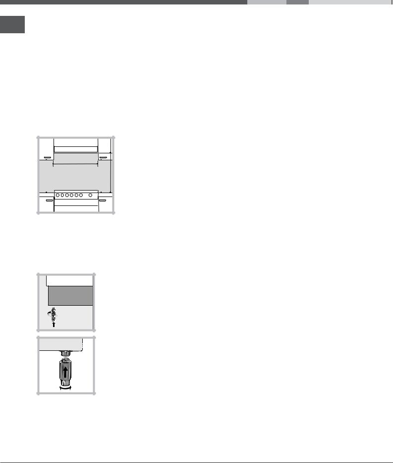
! L’appareil peut être installé à côté de meubles dont la hauteur ne dépasse pas celle du plan de cuisson.
! Assurez-vous que le mur en contact avec la paroi arrière de l’appareil est réalisée en matériel ignifuge résistant à la chaleur (T 90°C).
Pour une installation correcte :
•installez cet appareil dans une cuisine, une salle à manger ou un studio (jamais dans une salle de bains);
•si le plan de cuisson de la cuisinière dépasse le plan de travail des meubles, ces derniers doivent
être placés à au moins 200 mm de l’appareil;
|
|
|
|
• si la cuisinière est |
|
HOOD |
|
|
|
installée sous un |
|
|
|
|
élément suspendu, il |
||
|
|
|
|
||
Min. 600 mm. |
|
min. 650 mm. with hood |
min. 700 mm. without hood |
faut que ce dernier soit |
|
Min. 420 mm. |
Min. 420 mm. |
placé à au moins 420mm |
|||
de distance du plan. Il |
|||||
faut prévoir une distance |
|||||
de 700mm si les |
|||||
|
|
|
|
||
|
|
|
|
éléments suspendus sont |
|
|
|
|
|
inflammables (voir |
|
|
|
|
|
figure); |
•ne placez pas de rideaux derrière la cuisinière ou sur ses côtés à moins de 200 mm de distance;
•pour l’installation de hottes, conformez-vous aux
instructions de leur notice d’emploi.
Nivellement |
Pour mettre l’appareil bien à plat, vissez les pieds de réglage fournis aux emplacements prévus aux coins à la base de la cuisinière (voir figure).
Montage des pieds* par encastrement sous la base.
Raccordement électrique
Montez sur le câble une prise normalisée pour la charge indiquée sur l’étiquette des caractéristiques (voir tableau des caractéristiques techniques).
En cas de raccordement direct au réseau, il faut
intercaler entre l’appareil et le réseau un interrupteur à coupure omnipolaire ayant au moins 3 mm d’écartement entre les contacts, dimensionné à la charge et conforme aux normes NFC 15-100 (le fil de terre ne doit pas être interrompu par l’interrupteur). Le câble d’alimentation ne doit atteindre, en aucun point, des températures dépassant de 50°C la température ambiante.
Avant de procéder au branchement, assurez-vous que :
•la prise est bien munie d’une terre conforme à la loi;
•la prise est bien apte à supporter la puissance maximale de l’appareil, indiquée sur la plaquette signalétique;
•la tension d’alimentation est bien comprise entre les valeurs indiquées sur la plaquette signalétique;
•la prise est bien compatible avec la fiche de l’appareil. Si ce n’est pas le cas, remplacez la prise ou la fiche, n’utilisez ni rallonges ni prises multiples.
!Après installation de l’appareil, le câble électrique et la prise de courant doivent être facilement accessibles
!Le câble ne doit être ni plié ni excessivement écrasé.
!Le câble doit être contrôlé périodiquement et ne peut être remplacé que par un technicien agréé.
!Nous déclinons toute responsabilité en cas de non respect des normes énumérées ci-dessus.
Raccordement gaz
Pour raccorder l’appareil au réseau de distribution du gaz ou à la bouteille de gaz utilisez un tuyau flexible en caoutchouc ou en acier, conformément à la réglementation en vigueur. Assurez-vous auparavant que l’appareil est bien réglé pour le type de gaz d’alimentation utilisé (voir étiquette sur le couvercle : autrement voir ci-dessous). Si l’alimentation s’effectue avec du gaz liquide en bouteille, utilisez des régulateurs de pression conformes à la réglementation en vigueur dans le pays. Pour simplifier le raccordement, l’alimentation du gaz est orientable latéralement* : inversez l’about annelé avec le bouchon de fermeture et remplacez le joint d’étanchéité (fourni avec l’appareil).
! Pour un fonctionnement en toute sécurité, pour un meilleur emploi de l’énergie et une plus longue durée de vie de l’appareil, vérifiez que la pression d’alimentation respecte bien les valeurs indiquées dans le tableau Caractéristiques des brûleurs et des injecteurs (voir ci-dessous).
*N’existe que sur certains modèles
12
Raccordement gaz par tuyau flexible en caoutchouc
Assurez-vous que le tuyau est bien conforme aux normes applicables dans le pays d’installation. Le tuyau doit avoir un diamètre intérieur de : 8 mm en cas d’alimentation au gaz liquide; 15 mm en cas d’alimentation au gaz naturel.
Après avoir effectué le raccordement, assurez-vous que le tuyau :
•ne touche en aucun point à des parties pouvant atteindre plus de 50°C;
•ne soit pas soumis à traction ou torsion et ne présente pas de pliures ou étranglements;
•ne risque pas d’entrer en contact avec des corps tranchants, des arêtes vives, des parties mobiles et ne soit pas écrasé;
•puisse être facilement contrôlable sur toute sa longueur pour vérifier son état de conservation;
•ait moins de 1500mm de long;
•soit bien fixé à ses deux extrémités à l’aide de bagues de serrage conformes à la réglementation en vigueur dans le pays.
! Si une ou plusieurs de ces conditions ne peuvent être remplies ou que la cuisinière est installée dans des conditions de classe 2 – sous-classe 1 (appareil encastré entre deux meubles), il faut utiliser un tuyau flexible en acier (voir ci-dessous).
Raccordement gaz par tuyau flexible en acier inox, à paroi continue avec raccords filetés
Assurez-vous que le tuyau et les joints sont bien conformes aux normes applicables dans le pays d’installation.
Pour installer le tuyau, enlevez l’about annelé équipant l’appareil (le raccord d’entrée du gaz à l’appareil est fileté 1/2 gaz mâle cylindrique).
! Procédez au raccordement de manière à ce que la longueur du tuyau ne dépasse pas 2 mètres d’extension maximale. Veillez à ce que le tuyau ne soit pas écrasé et ne touche en aucun point à des parties mobiles.
Vérification de l’étanchéité
Une fois l’installation terminée, vérifiez l’étanchéité de tous les raccords en utilisant une solution savonneuse, n’utilisez jamais de flamme.
Adaptation aux différents types de gaz
L’appareil peut être adapté à un type de gaz autre que celui pour le quel il a été conçu (indiqué sur l’étiquette de réglage sur le couvercle).
Adaptation du plan de cuisson
FR
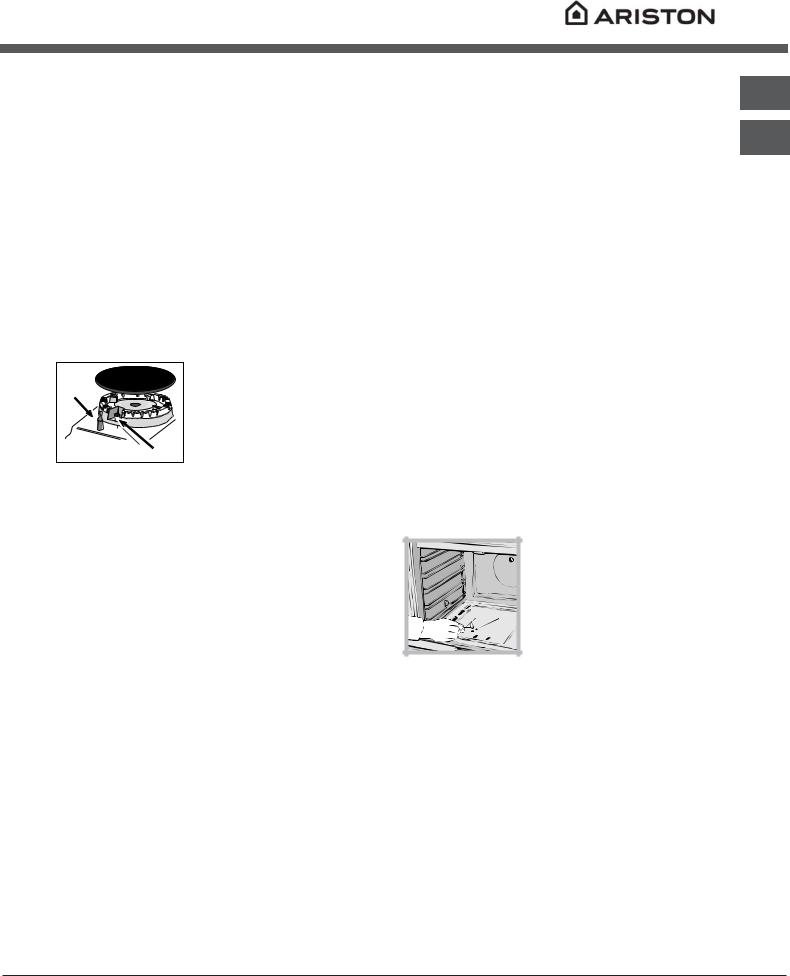
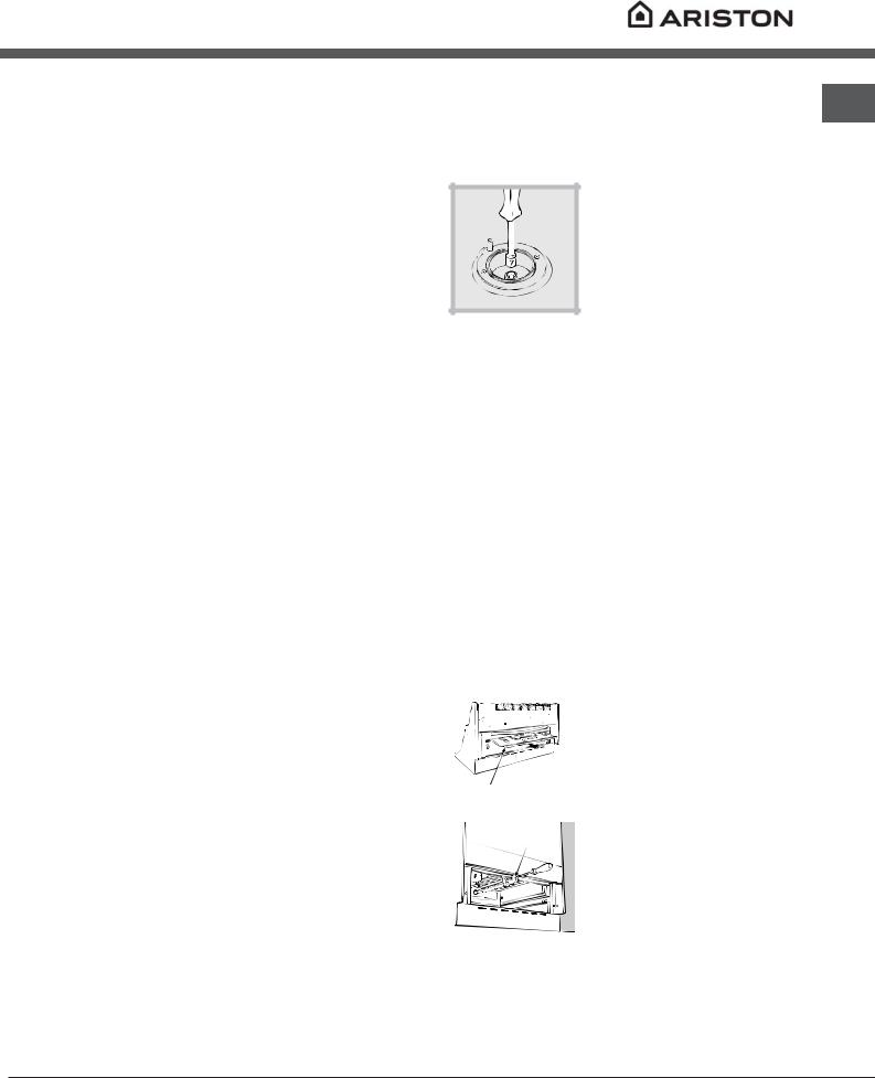
Remplacement des injecteurs des brûleurs du plan de cuisson:
1.enlevez les grilles du plan de cuisson et sortez les brûleurs de leur logement;
2. dévissez les injecteurs à
l’aide d’une clé à tube de 7mm (voir figure), et remplacez-les
par les injecteurs adaptés au
nouveau type de gaz (voir tableau Caractéristiques des brûleurs et des injecteurs) ;
3.remontez les différentes parties en effectuant les opérations dans le sens inverse.
Réglage des minima des brûleurs du plan de
cuisson :
1.placez le robinet sur la position minimum; 2.enlevez le bouton et tournez la vis de réglage positionnée à l’intérieur ou sur le côté de la tige du robinet jusqu’à obtenir une petite flamme régulière;
!En cas de gaz naturel, il faut dévisser la vis de réglage en tournant dans le sens inverse des aiguilles d’une montre;
3.vérifiez si, en tournant rapidement le robinet du maximum au minimum, le brûleur ne s’éteint pas.
!Les brûleurs du plan de cuisson ne nécessitent pas de réglage de l’air primaire.
Adaptation du four
Remplacement du brûleur du four: 1. enlever le tiroir chauffe-plats;
|
2. enlever la protection |
|
|
|
coulissante A |
|
(voir figure); |
A |
|
|
3. déposer le brûleur du four |
|
|
|
|
V |
après avoir enlevé la vis V (voir |
|
figure); |
|
pour simplifier cette opération, |
|
démonter auparavant la porte |
|
du four. |
|
|
13
 Loading...