

Page 1
aCAUTION
Never touch the rear brake pedal after removing the wheel. If you do, the caliper
pistons may be pushed o ut of thei r seats,
and brake fluid wil l be spilled. Should
you accidentally do this, take your vehicle to your Local APRILIADealer who will
know how to repair this damage.
REASSEMBLY
◆
Apply a thin film of grease to the outer
seals of the rear wheel hub.
aCAUTION
While reassembling the wheel, be careful not to damage the brake line, the
disc and the pads.
◆
Position the wheel centrally in the swinging arm, on the support (1).
aWAR NING
Keep your fing ers well away from the
chain and sprocket. You could ea sily
lose a finger if it becomes pinched between thes e two pa rts. Us e heavy work
gloves while installing the rear wheel.
Never attempt to line the rear wheel up
using your fingers. Failure to heed this
warning can result in serious personal
injury.
◆
Move the wheel as f ar for war d as po ssible, to install the drive chain (6) on the
rear sprocket (7).
◆
Pull the rear wheel backwards until the
bearing holes are lined up with the holes
in the swinging arm.
◆
Lightly grease the outside of the axle (2).
◆
Install the washer (5) on the axle (2).
NOTE To facilitate the insertion of the
axle (2), slightly raise the wheel.
◆
Install the axle (2) completely through
the wheel from the left side.
NOTE Ensure that the ax le (2) is pushe d
all the way home with the head in the appropriate seat on the left chain tightener.
◆
Install the washer (4) and tighten the nut
(3) finger tight.
◆
Remove the support (1) from under the
rear tire.
◆
Check the chain tension, see p. 78
(DRIVE CHAIN).
◆
Tighten the nut (3).
Wheel nut (3) tightening torque:
72.33 ftlb (100 Nm).
aWARNING
After servicing t he brakes, always
check them for function. If the stroke of
the lever or pedal is excessive, or if you
detect that the effect iveness of the
brakes is reduced in any way, have y our
vehicle serviced by your Local APRILIA
Dealer. It may be necessary to ha ve
your dealer bleed the sy stem, or ther e
may be some other problem with the
brake system.
Never ride your veh i c le in traffic immediately after servicing the brakes.
Always apply the brake pedal or lever
several times before riding your vehicle .
Then, try yo ur v eh i cl e in a park ing lo t or
other safe area with little t raff ic to ens ure
that the brakes are working properly.
Failure to observe this warning can lead
to a serious accident with subsequent serious injury or death.
Check the wheel centering.
Have the t ightening torques, centerin g
and balancing of the wheel checked by
your Local APRILIA Dealer. These are
critical safety operations, and failure to
observe this warning could lead to an
upset with subsequent serious injury or
death.
use and maintenance Pegaso 650
-
77
Page 2
$2)6%#(!).
Carefully read p. 61 (MAINTENANCE).
Every 312 mi (50 0 km) check the conditions, the wear, the play (tension) and the
lubrication of the drive chain.
The vehicle is equipped with an endle ss
chain. There is no master link used.
aWARNING
An excessively loose cha in can come
off the sprocket which can result in a
serious accident and serio us dama ge to
the vehicle from the upset and subsequent serious injury or even death.
Do not ride your vehicle with an improperly adjusted chain, see p. 79 (ADJUSTMENT).
To inspect the conditio n of the chain,
grasp the chain where it goes around
the sprocket and try to pull it away from
the sprocket. If you can move it more
than one-eighth of a n inch away from
the sprocket, the chain is worn out and
the chain and both front and rear
use and maintenance Pegaso 650
78
-
sprockets must be replaced. See your
Local APRILIADealer.
aCAUTION
Lack of maintenance can cause premature wear of the chain an d damage to
the sprockets.
Maintain your chain more often if your
vehicle is used on dusty or muddy roads.
aWAR NING
Before carring out the following operations, let the engine and the exhaust silencer cool down until they reach room
temperature, in order to avoid burns.
aWAR NING
Keep your fingers well clea r of the chain
and sprocket, especially if you are turning the rear wheel while working on the
vehicle. You can easily be seriously injured if a finger is caught between the
chain and sprocket. Use work-gloves to
carrying out these operation.
CHECKING THE PLAY
To check the play:
◆
Stop the engine.
◆
Place the vehicle on the center stand,
see p. 59 (POSITIONING THE VEHICLE
ON THE STAND).
◆
Shift to neutral.
◆
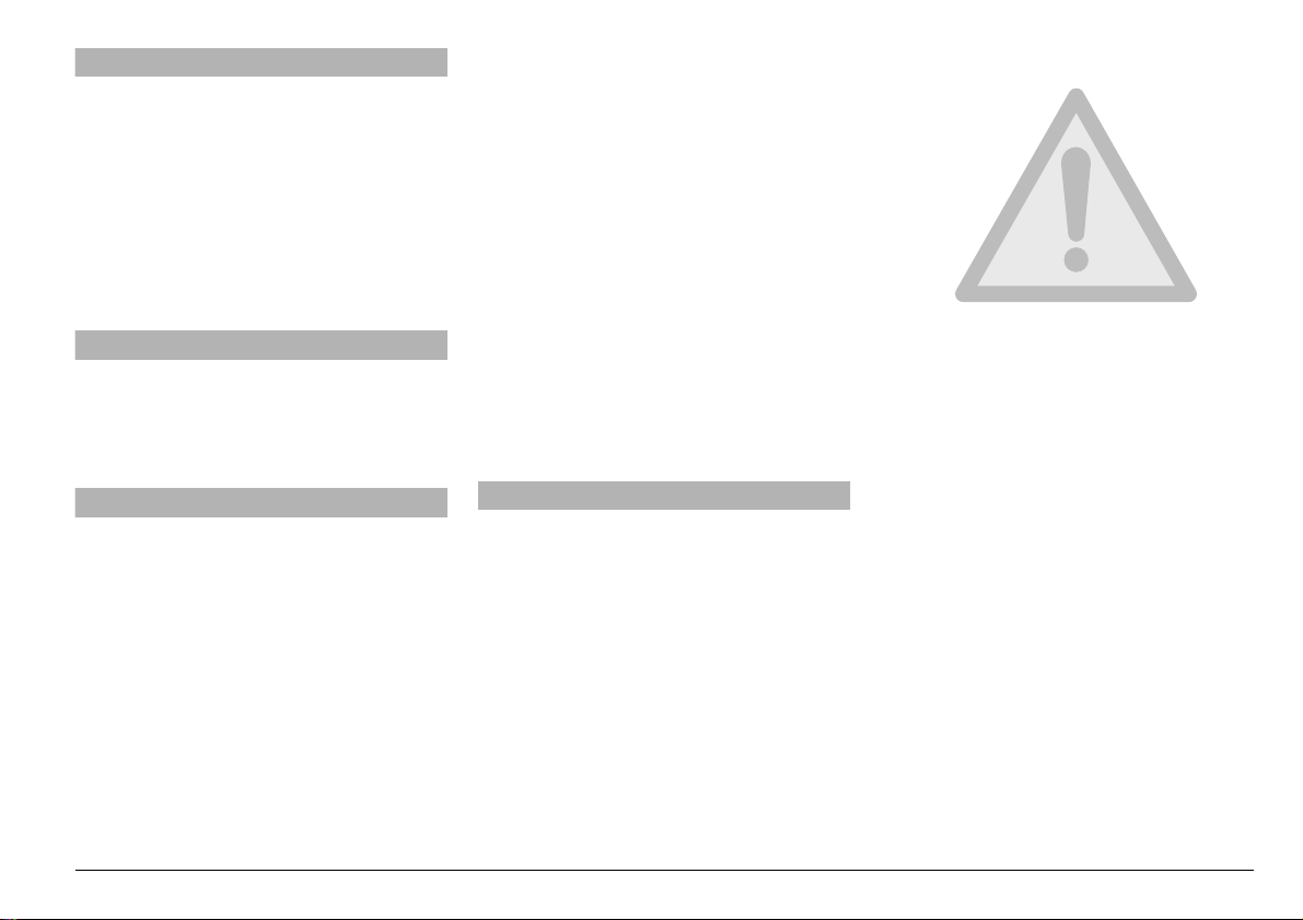
Check the chain p lay. It shoul d be 1 .38 –
1.77 in (35 – 45 mm) at mid-bottom span
as shown abov e.
◆
Move the vehicle forward or backward,
or support the rear wheel in the air and
turn the wheel to several positions, to
check the chain slack at several locations. If the slack is markedly different
with the wheel in different positions, the
chain and sprockets must be replaced.
aWARNING
Do not ever operate your vehicle with a
damaged chain. This could cause
wheel seizure which could lead to an
Page 3

upset with subsequent serious injury or
death. Lubricate your chain frequently
to minimize the possibility of this kind
of damage, see p. 79 (CLEANING AND
LUBRICATION).
If the play is the same at several locati ons, but
is more or less than 1.38 – 1.77 in (35 – 45
mm), adjust it, see p. 79 (ADJUSTMENT).
ADJUSTMENT
To adjust the chain tension:
◆
Place the vehicle on the center
stand,see p. 59 (POSITIO NING THE
VEHICLE ON THE STAND).
◆
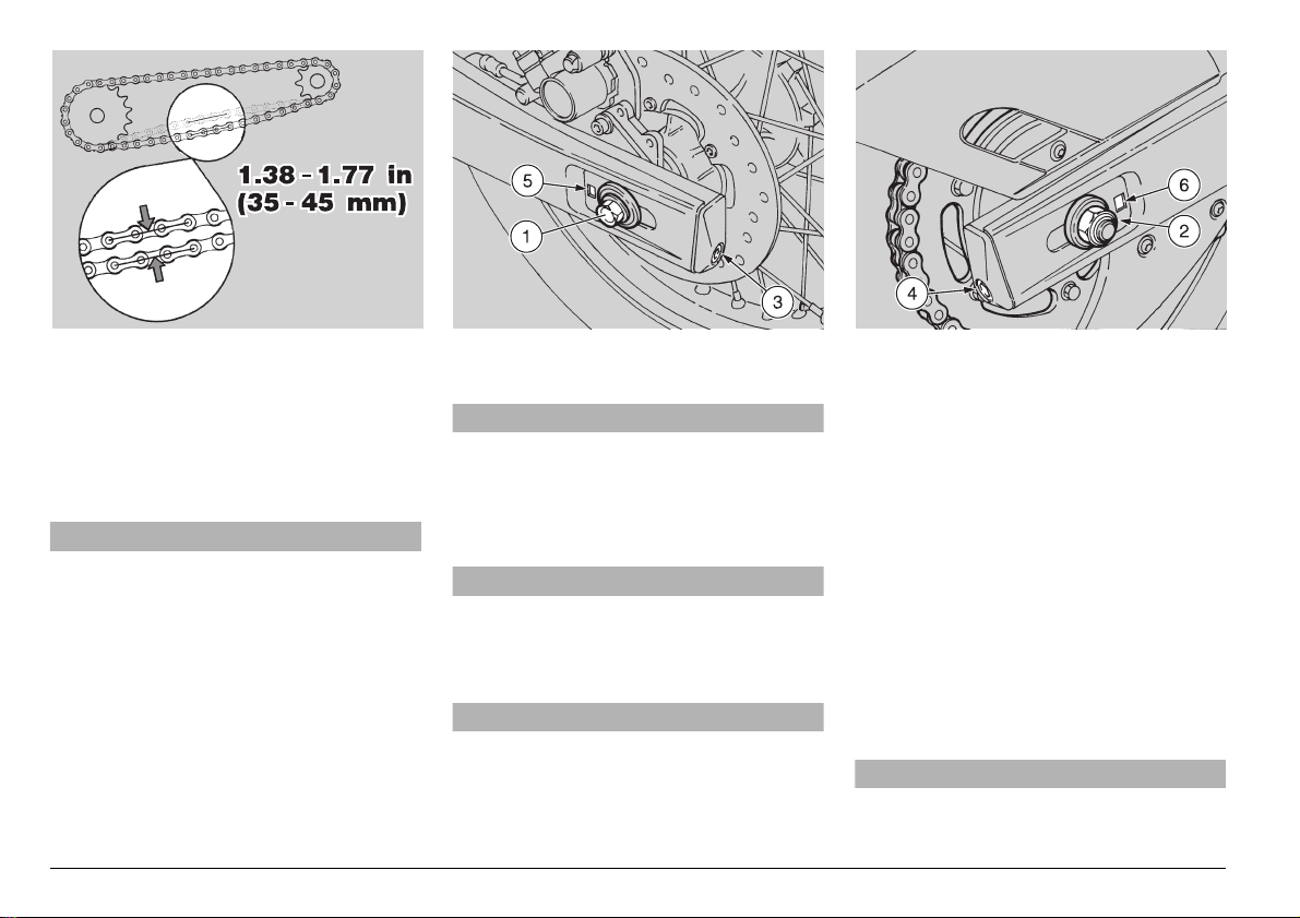
Hold the axle (1) from rotating with an
appropriate Allen wrench.
Wheel nut (2) tightening torque:
72.33 ftlb (100 Nm).
◆
Loosen the nut (2) to several turns.
NOTE In order to facilitate whe el c en ter-
ing, numbered reference mark s are prov ided on the swinging arm, which correspond
with marks on the adjusters (3) and (4).
These marks may be seen through the
slots (5) and (6).
◆
Adjust the left (3) and right (4) tension
adjusters to obtain the appropriate chain
play, ensuring that the slot (5) and (6) coincide with the same reference marks on
each side of your vehicle.
◆
Hold the axle (1) from rotating with an
appropriate Allen wrench.
◆
Tighten the nut (2).
Wheel nut (2) tightening torque:
72.33 ftlb (100 Nm).
◆
Check the chain play again, see p. 78
(CHECKING THE PLAY).
CHECKING THE WEAR OF THE CHAIN
AND SPROCKETS
In addition to the check, see p. 78 (CHECKING THE PLAY), inspect the chain an d
sprockets to make sure that there are no:
– damaged rollers; – loose pins; – dry,
rusty, crushed or seized links; – excessive wear; – missing “O” rings; – sprock-
et or teeth excessively worn or damaged.
You may check the wear of the chain and
sprocket by grasping the chain where it con-
tacts the rear sproc ket, and pull ing it away
from the sprocket as far as you can. If you
are able to pul l the chai n far enough away
from the sprocket so that you can see light
between the side plates of the chain and the
sprocket teeth, the chain and sprocket are
worn out and should be replaced.
NOTE Always replace both sprockets
and the chain wh en any of these co mponents are replaced.
aCAU TION
If chain rollers are d amaged, the pins
and/or the O rings are loose or missing,
both sprockets as well as the chain
must be replaced.
aCAU TION
Lubricate the chain frequently, especially if it displays any rust or if it is dry to
the touch. If, after lubricating the chain,
it still has li nks which ca nnot be tu rned
easily, the chain must be replaced.
◆
Finally, check the wear of the rear fork
protection shoe.
CLEANING AND LUBRICATION
aCAUTION
The drive chain is provided with O ri ngs
among the links, in order to keep the
grease inside them.
Carry out chain adjustment, lubrication,
cleaning and replacement with great
care. Remember to keep your fingers
clear of the chain and sprocket.
Never wash the chain with water jets,
steam jets, high-pressure water jets and
highly inflammable solvents.
◆
Wash the chain with a non-flammable
solvent. If your chain rusts quickly, lubricate it more often.
Lubricate the chain every 312 mi (500 km)
or whenever it appears dry.
After washing the chain and letting it dry,
lubricate it exclusively with spray grease
for chains provided with sealing rings, see
p. 104 (LUBRICANT CHART).
aCAUTION
Make sure that the chain lubric ant you
use is appropriate for “O” ring chains.
There are some lub ricants available
which contain subst ances which will
destroy the “O” rings in your chain.
If you have any question, contact your
Local APRILIADealer.
NOTE Do not use the vehicle immedi-
ately after lubricat ing the ch ain , gi ve the lubricant a chance to dry, otherwise the
chain will spray the lubricant all over you
and your vehicle.
use and maintenance Pegaso 650
-
79
Page 4
2%-/6).'4(%&5%,4!.+
Carefully read p. 35 (FUEL) and p. 61
(MAINTENANCE).
aWARNING
Risk of fire.
Wait until the engine and th e exhau st silencer have completely cooled down.
Fuel vapors are noxious for your health .
Make sure that the room in which you
are working is properly ventilated.
Do not inhale fuel vapours.
Do not smoke and do not use naked
flames.
DISPOSE OF UNWANTED FUEL PROPERLY.
◆
Remove the saddle, see p. 81 (REMOVING THE SADDLE).
◆
Drain the fuel tank completely, see p. 97
(DRAINING THE FUEL TANK).
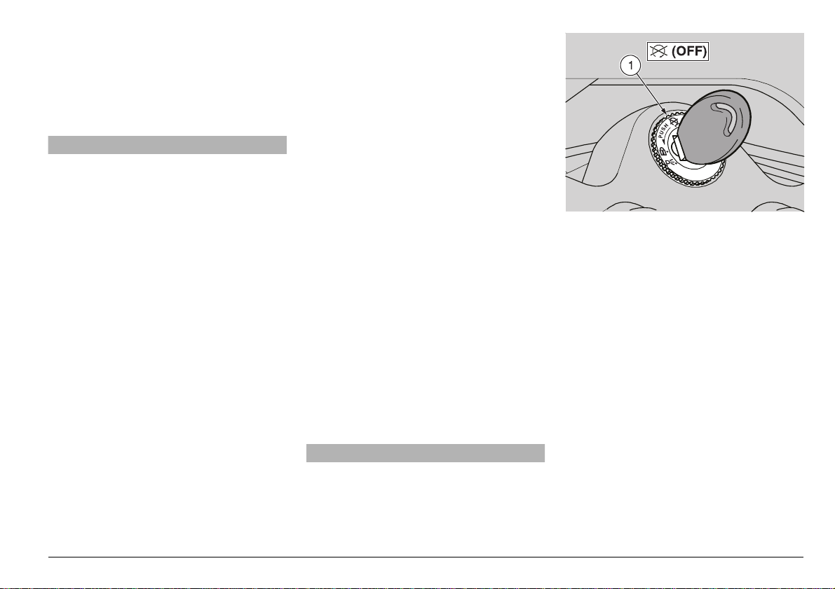
◆
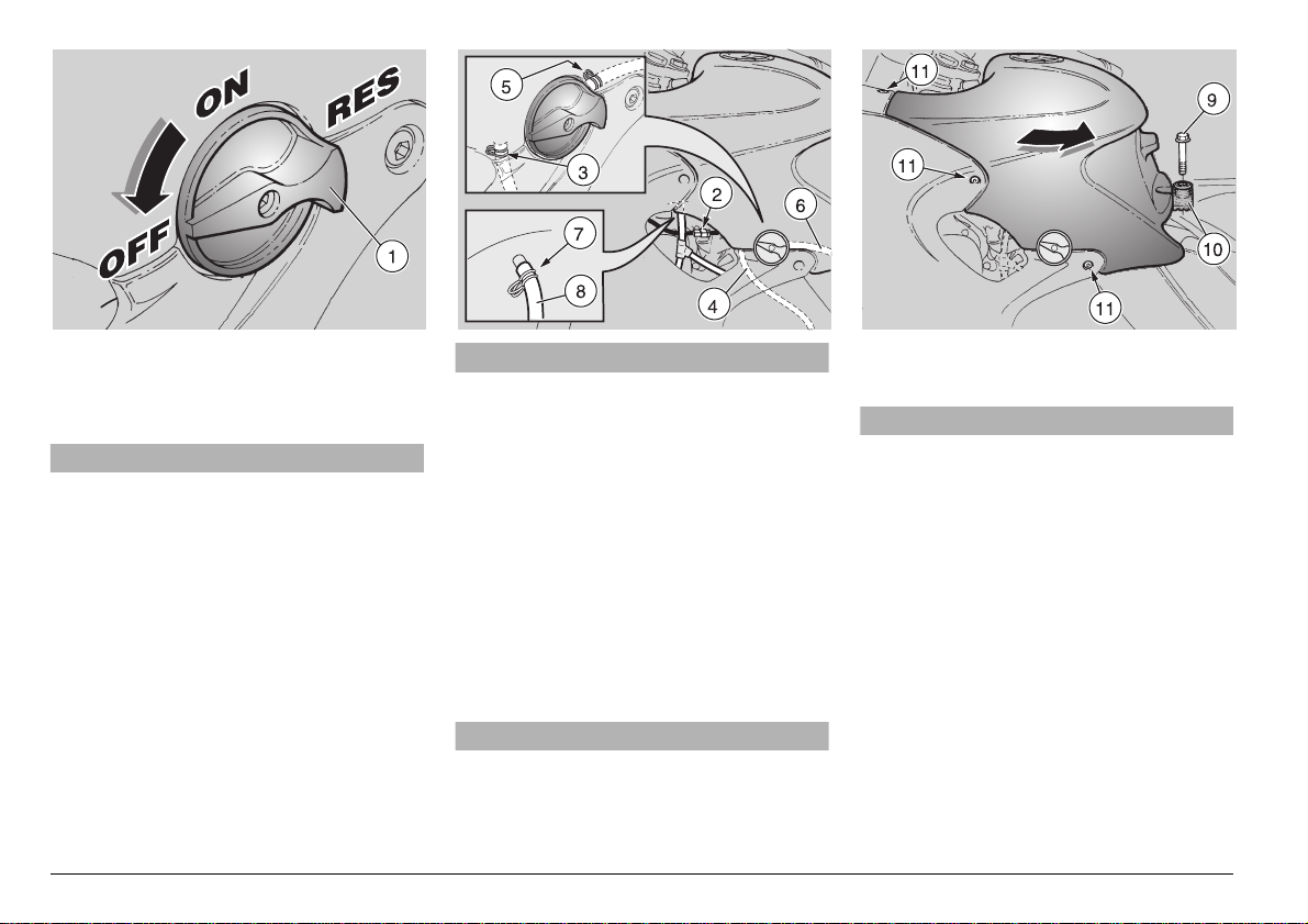
Move the fuel valve leve r (1) to the “OFF”
position.
use and maintenance Pegaso 650
80
-
aCAUTION
Handle the plastic and painted components with care and avoid scraping or
damaging them.
Be careful do n ot damage the electric
cables.
NOTE To release th e clam ps , us e a p air
of pliers.
Working from the left side of the vehicle:
◆
Disconnect the electric connector (2) of
the low fuel sensor.
◆
Release the clamp (3) and disconnect
the water drain line (4 ) from the fuel tank.
◆
Release the clamp (5) and remove the
fuel line (6) from the fuel valve.
aWAR NING
Danger! Some fuel may spill.
◆
Plug the free end of the fuel line (6) and
attach it to the vehicle with a wire or ta pe
in the vertical position.
◆
Release the clamp (7) and remove the
breather line (8) from the fuel tank.
aCAU TION
Upon reassem bly, be sure that the line s (4)
and (8), the cl amp (3) and (7) and, m ost im portant the fuel line (6) and clamp (5), are
properly in stal led.
◆
Unscrew and remove the central screw (9).
◆
Take the rubber element (10) complete
of the washer and the bush.
◆
★ Unscrew and remove the three
screws (11).
◆
Slightly raise the rear part o f the fuel t ank
and at the same time withdraw it from its
two seats (i n the front part), by pulling it
backwards.
NOTE Upon reassembly, make sure
that the fuel tank fits correctly into the relative seats in the front part.
Page 5
2%-/6).'4(%3!$$,%
Carefully read p. 61 (MAINTENANCE).
◆
Place the vehicle on the center or side
stand, see p. 59 (POSIT IONING THE
VEHICLE ON THE STAND).
◆
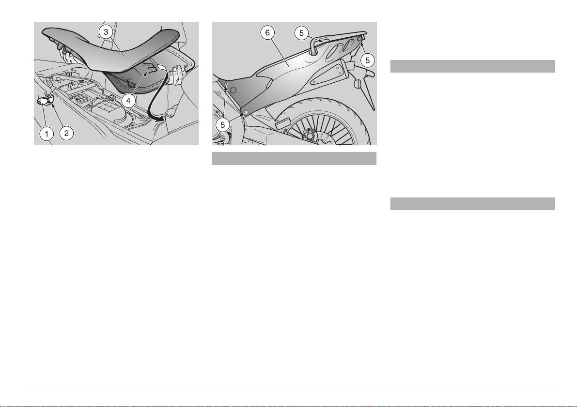
Insert the key (1) in the lock (2).
◆
Turn the key (1) clockwise.
◆
Raise and remove the saddle (3).
Upon reassembly:
NOTE Before l owering and locking the
saddle, make sure that you have not left
the key in the glove/tool kit compart ment.
◆
Insert the tang (4) of th e saddle in the appropriate seats (see figure).
◆
Lower the saddle and press the its rear
part.
aCAUTION
Do not leave you r vehicle unatte nded
without ensuring that the saddle (3) is
properly positioned and l ocked. Should
you forget and ride away with the saddle loose, you could be injured.
2%-/6).'4(%2)'(4!.$ ,%&4
3)$%0!.%,3
Carefully read p. 61 (MAINTENANCE).
aWAR NING
Before carrying out the following operations, let the engine and the exhaust silencer cool down until they reach room
temperature, in order to avoid burns.
◆
Remove the saddle, see beside (REMOVING THE SADDLE).
◆
Place the vehicle on the center stand,
see p. 59 (POSITIONING THE VEHICLE
ON THE STAND).
◆
Unscrew and remove the four screws
(5).
aCAUTION
Handle the plastic and painted components with care and avoid scraping or
damaging them.
◆
Remove the side panel (6).
use and maintenance Pegaso 650
-
81
Page 6
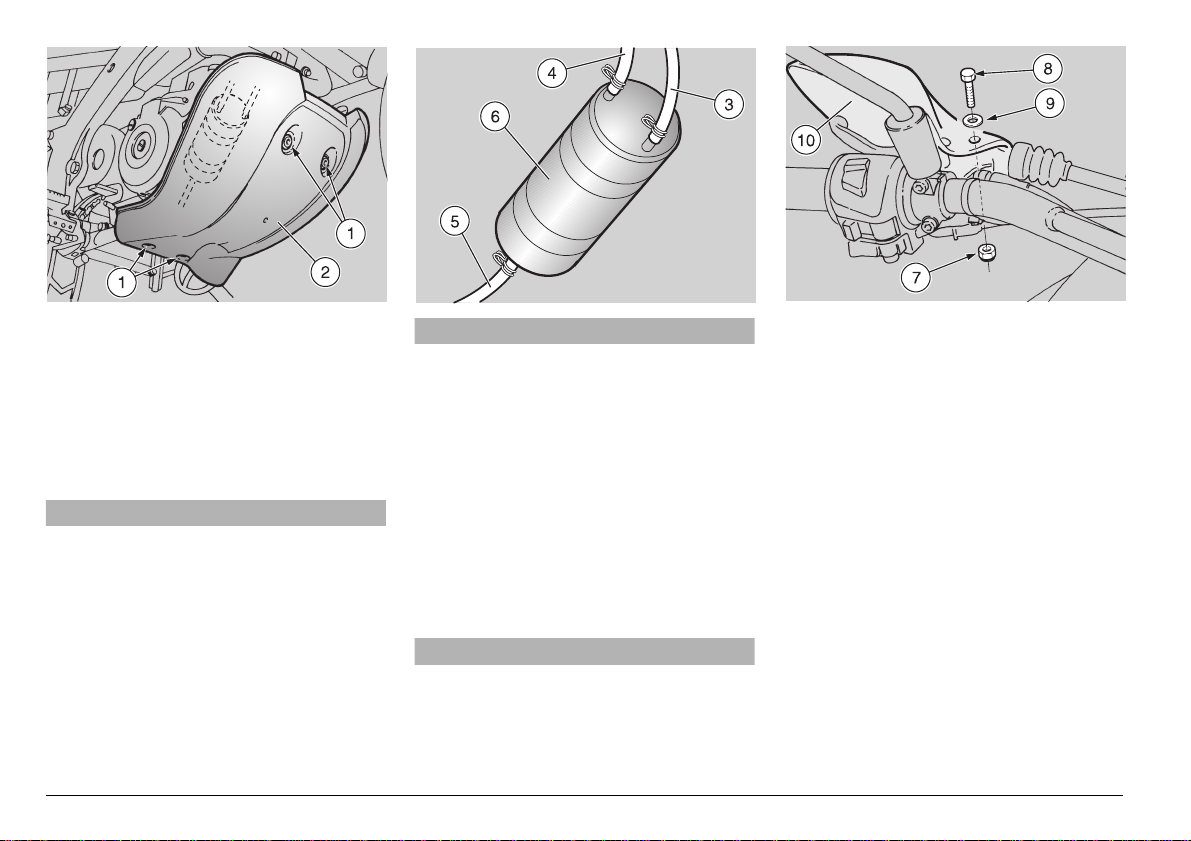
2%-/6).'4(%/),0!.'5!2$
Carefully read p. 61 (MAINTENANCE).
◆
Place the vehicle on the center stand,
see p. 59 (POSITIONING THE VEHICLE
ON THE STAND).
◆
Unscrew and remove the four screws
(1).
aCAUTION
While removing the oil pan guard (2),
pay extra care not to pull, force or damage the three lines (3), (4), (5) of the carbon canister (6).
◆
Remove the oil pan guard (2) only as
much as necessary to disconnect the
three lines (3), (4), (5) of the carbon canister.
aCAUTION
WHILE REASSEMBLING, PA Y EXTRA
CARE NOT TO INVERT THE LIN ES OF
THE CARBON CANISTER.
◆
Mark the lines and the relevant couplings, in order to be able to reassemble
them correctly.
NOTE To release th e clam ps , us e a p air
of pliers.
◆
Release the clamps and remove the
lines (3), (4), (5).
◆
Remove completely the oil pan guard
(2).
aCAUTION
While reassembling the oil pan guard
(2), pay extra care and ensure not to
crash the lines (3), (4), (5).
2%-/6).'4(%(!.$'5!2$3
Carefully read p. 61 (MAINTENANCE).
◆
Hold the nut (7) from rotating with an appropriate Allen wrench.
◆
Remove the screw (8) the washer (9).
◆
Remove the hand-guard (10).
use and maintenance Pegaso 650
82
-
Page 7
)$,).'!$*534-%.4
Carefully read p. 61 (MAINTENANCE).
If the idle becomes irregular, too fast, or
too slow, it must be adjusted.
To adjust the idle:
aWAR NING
Exhaust gases co ntain carbon monoxide, which is extremely poisonous if inhaled.
Do not start the engine in closed or badly-ventilated rooms.
Failure to observe this warning may
cause loss of consciousness or even
lead to death by asphyxia.
◆
Ride for a few miles until the engine
reaches normal running temperature,
see p. 15 (Coolant temperature indicator
h”).
“
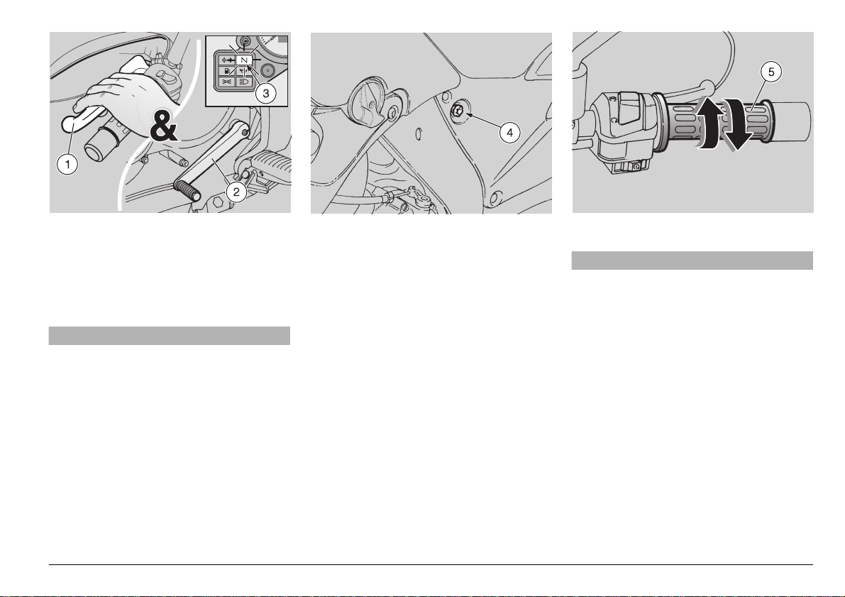
◆
Pull in the clutch lever (1) c ompletely an d
put the shift lever (2) in neutral so that
the green “
◆
Keep the vehicle in vertical position, with
both wheels resting on the ground.
◆
Observe the tachometer.
The engine must idle 1,400 ± 100 rpm, CO
1% [+ 1% – 0.5% (total range from 0.5%
to 2%)].
q” light (3) is on.
If it does not:
aWAR NING
Do not adjust the air adjusting screw.
Doing so will upset t he idling performance of your engine, as well as increasing exhaust emissions.
◆
Adjust the knob (4) positioned on the left
side of the vehicle.
Rotate the knob clockw ise to increase
engine rpm.
Rotate the knob counterclockwise to decrease the engine rpm.
◆
Accelerate and decelerate the engine a
few times to make sure, when the throt tle
returns to idle, that the engine idle speed
is still correct.
NOTE If necessary, contact your Local
aprilia Dealer.
use and maintenance Pegaso 650
-
83
Page 8
!$*534).'
4(%4(2/44,%#/.42/,
Carefully read p. 61 (MAINTENANCE).
This vehicle is equipped with two throttle
cables.
The following information may refer to just
one throttle cable but should be observed
with regard to both throttle cables.
aWARNING
If the throttle sticks open, it may cause
a collision with another ve hicle, or an
upset.
If the throttle sticks, kill the engine with
the engine stop switch located on the
right handlebar.
Do not attempt to restart the engine until the throttle has been repaired and
works perfectly. Failure to obey this
warning can lead to a runaway with se riously injuries or even death.
If any fastener in the throttle system becomes loose, likewise you w ill lose control of your vehicle.
Either si tuation c an lead to an upset or
collision with subsequent serious injury
or death.
Your vehicle is equipped with a double cable throttle. One cable opens the throttle
when you rotate the throttle grip toward
you; the other closes the throttle when you
rotate th e gr ip aw ay from y ou. I t i s es sen tial, when you release the throttle grip, that
it automatically return to the idle position.
This double cable arrangement enhances
safety by providing for positive closing of
the throttle.
aWAR NING
In the event of a throttle sticking emergency, always kill the engine using the
engine stop switch located ne ar the
throttle grip on the right handlebar.
Never use your vehicle if the throttle
does not automatically fully return to
the idle position whe n the throttle gr ip
is released. Contact your Local APRILIA
Dealer for repairs. Failure to heed this
warning can lead to a serious accident
and subsequent injury or even death.
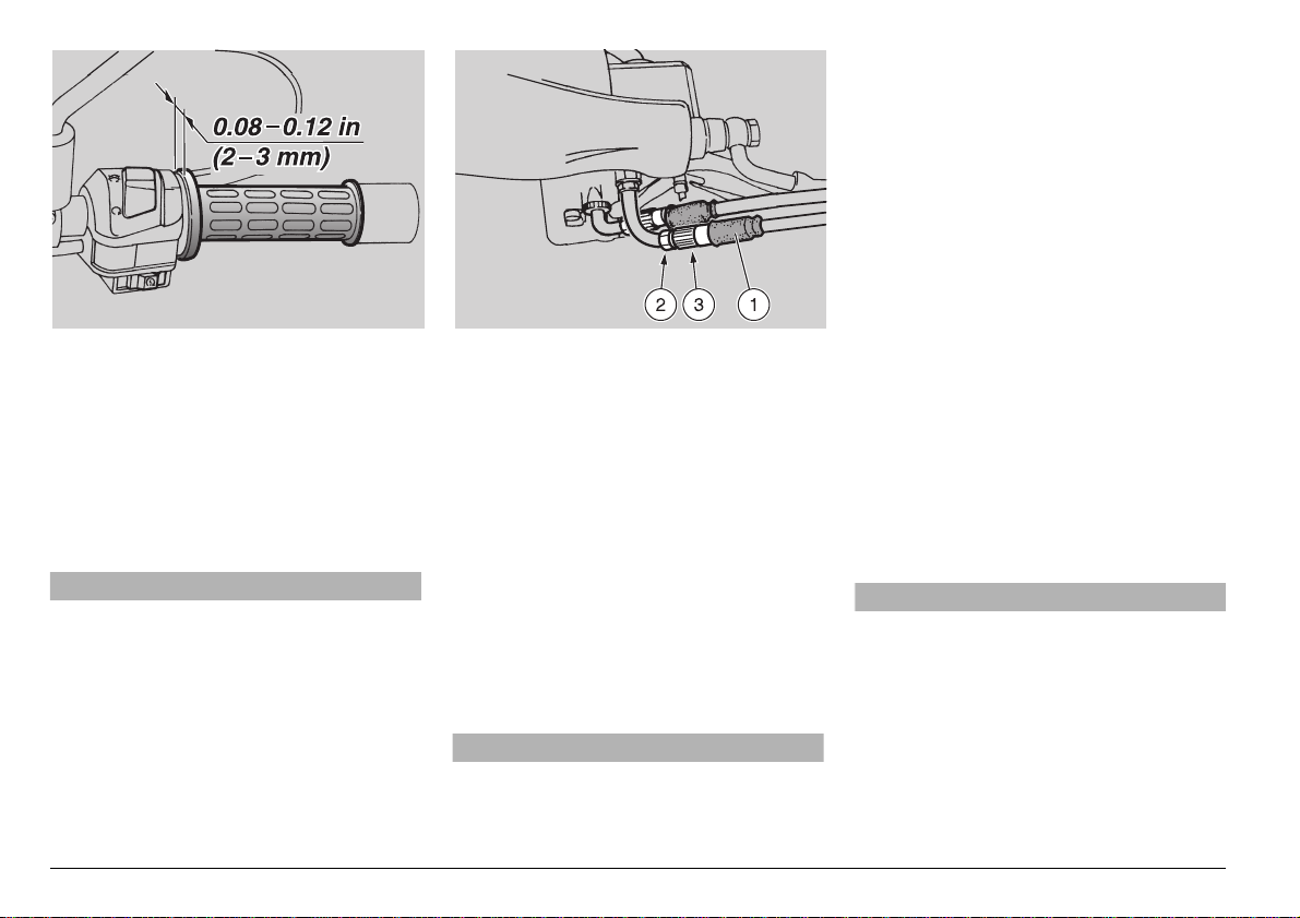
The play of the throttle cable must be between 0.08 – 0.12 in (2 – 3 mm), measured at the edge of the grip, see the illustration above.
To adjust the cable:
◆
Place the vehicle on the center stand,
see p. 59 (POSITIONING THE VEHICLE
ON THE STAND).
◆
Pull back the rubber boot (1).
◆
Loosen the lock nut (2).
◆
Rotate the adjuster (3) in such a way as
to restore the prescribed value.
◆
After the adjustment, tighten the lock nut
(2) and check the play again.
◆
Replace the rubber boot (1).
◆
Repeat the adjustment for the second
cable.
aWARNING
Exhaust gases contain carbon monoxide, which is extremely poisonous if inhaled.
Do not start the engine in c losed or badly-ventilated rooms.
Failure to observe this warning may
cause loss of consciousness or even
lead to death by asphyxia.
use and maintenance Pegaso 650
84
-
Page 9
aWAR NING
After you have adjusted the throttle, rotate the handlebars full left and full right
with the engine idling. Check to ensure
that the idle sound is not affected by
this. Also check that the throttle
smoothly and fully closes when released.
!$*534).'4(%#/,$34!24
#(/+%#/.42/,
Carefully read p. 61 (MAINTENANCE).
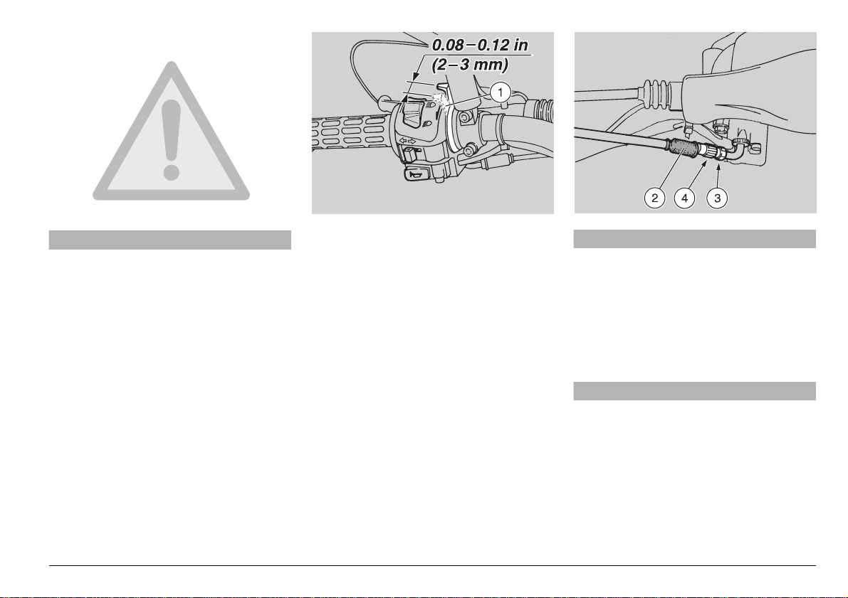
The play of the c old s tart ca ble m ust b e between 0.08 – 0.12 in (2 – 3 mm), measured on the lever (1).
To adjust the cable:
◆
Place the vehicle on the center stand,
see p. 59 (POSITIONING THE VEHICLE
ON THE STAND).
◆
Pull back the rubber boot (2).
◆
Loosen the lock nut (3).
◆
Rotate the adjuster (4) in such a way as
to restore the prescribed value.
◆
After the adjustment, tighten the lock nut
(3) and check the play again.
◆
Replace the rubber boot (2).
e
aWAR NING
Exhaust gases co ntain carbon monoxide, which is extremely poisonous if inhaled.
Do not start the engine in closed or badly-ventilated rooms.
Failure to observe this warning may
cause loss of consciousness or even
lead to death by asphyxia.
aWAR NING
After you have adjus ted the cold start,
rotate the handlebars full left and full
right with the engine idling. Check to
ensure that the idle sound is not affected by this.
use and maintenance Pegaso 650
-
85
Page 10
30!2+0,5'
Carefully read p. 61 (MAINTENANCE).
Clean the spark plug every 3,750 mi
(6,000 km); change it every 7,500 mi
(12,000 km).
Periodically remo ve the spark plug and
clean it carefully, removing carbon deposits; change it if necessary.
To reach the spark plug:
◆
Remove the fuel tank, see p. 80 (REMOVING THE FUEL TANK).
To remove and clean the spark plug:
aWARNING
Before carrying out the following ope rations, let the engine and the exhaust silencer cool down until they reach room
temperature, in order to avoid burns.
◆
Remove the spark plug cap (1).
use and maintenance Pegaso 650
86
-
aWARNING
During this operation, always wear goggles which provide your eyes with 360°
protection. Be very careful using compressed air jets, they can cause serious
personal injury if directed towards your
body.
◆
Using compressed air, blow all the dirt
away from the base of the spark plug.
Using the special spark plug wrench
from the tool kit, unscrew the spark plug.
Make sure that no dirt falls into the cylinder through the spark plug hole.
◆
Inspect the spark plug, and insure that
there are no carbon deposits nor corrosion marks on either electrode or the ceramic nose that surrounds the center
electrode. If necessary, clean the spark
plug with a proprietary spark plug cleaner, and a stainless steel brush.
◆
Using compressed air, carefully blow out
the spark plug after you have cleaned it.
Inspect for cracks on the insulating mate rial, electrode corrosion or erosion, or
deposits that you cannot remove.
If the spark plug shows any of these defects, it must be replaced.
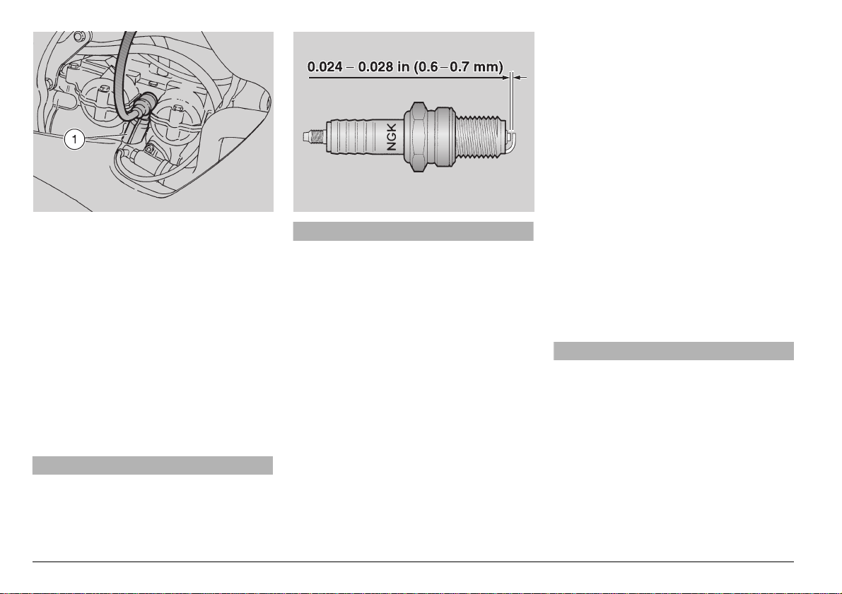
◆
Check the spark plug gap with a thickness gauge.
◆
The gap must be 0.024 – 0.028 in (0.6 –
0.7 mm); if necessary adjust it, carefully
bending the ground (outside) electrode.
◆
Make sure the gasket is in good condition. With the gaske t on, screw th e spark
plug into the head by hand.
◆
Tighten the spark plug with the spark
plug wrench, approxim ately one-ha lf tur n
after it first snugly contacts the cylin der
head.
Spark plug tightening torque:
14.47 ftlb (20 Nm).
aCAU TION
The spark plug must be well tightened,
otherwise the engine may overheat and
be seriously damag ed.
Use the recommended type of spark
plug only, see p. 100 (TECHNICAL DATA), in order not to compromise the life
and performance of the engine.
◆
Position the spark plug cap (1) properly,
so that it does not come off du e to the vi brations of the engine.
◆
Replace the fuel tank, see p. 80 (REMOVING THE FUEL TANK).
Page 11
"!44%29
Carefully read p. 61 (MAINTENANCE).
Check the electrolyte level and the tightness of the terminals after the first 62 5 mi
(1,000 km) and su ccessively every 3 ,750
mi (6,000 km) or 8 months.
aWAR NING
Batteries, when charged, give off hydrogen gas, which is highly explosive.
Therefore, do not smoke while working
on or around the battery, and keep naked
flames or sparks away from the battery.
Keep gasoli ne and o ther flammabl e substances well away from the battery, since
a battery spa rk could easi ly ignit e them
and cause a devastating fire.
Battery electro lyte is toxic and cau stic
and can seve rely burn your eyes or
skin. Always wear tight fitting goggles
and protective clothing when handling
battery electrolyte. It is particularly important for you to protect your eyes
since even a minuscule amount of battery acid could destroy your vision.
Should you accidentally get even the
smallest amount of battery electrolyte
on your skin or eyes, immediately flush
with large quantities of clear cool water
and immediately seek professional
medical attention.
If someone should accidentally swallow
battery electrolyte, drink a large quantity of milk or cool cle ar water a nd conti nue with milk of magnesia or vegetable
oil. Seek pro fessional medi cal assistance immediately.
Since the battery gives off exp losive hy drogen gas, especially when it is being
charged, when you are charging a battery, make sure that the room is properly ventilated. Do not inhale the gases
released during charging. Do not permit any open flames , sparks or cigarettes or any other source of heat anywhere near the battery while it is
charging.
Do not tip the vehicle too much, or tip
the battery too much , to avoid electrolyte leaking out. Should you accid entally spill battery electrolyte on any part of
your vehicle, immediately wa sh it off
with lots of cool clear water. Spills may
be neutralized with a mixture of baking
soda and water, as we ll. Th is is particularly important, as the battery electrolyte will severely corrode metallic parts
and destroy t he finish of plas tic and
painted parts.
aCAU TION
Never invert the battery cables. Observe the proper polarity of the battery.
Incorrectly attaching the battery to your
vehicle will irreparably destroy the electrical system of your vehicle.
Connect and disc onnect the battery
only with the ignition switch (1) in the
m” (OFF) position.
“
First connect the positive cable red (+),
then the negative (–).
Disconnect the negative cabl e (–) first,
then the positive red (+).
If your battery needs to be charged, use
a constant voltage, or “taper” charger,
with a current rating no greater than
1/10th the capacity of the battery (i.e.,
for a 50 amp hour battery, th e ma xim um
charging current should be 5 amps).
Use of a more powerful charger can not
only damage the battery irrepara bly, but
could cause it to overheat and explode.
If your battery is equipped with an overflow tube, always ensure that it is properly installed, and properly routed. Failure
to adhere to this instruction can cause
corrosive fumes from the battery to cause
serious damage to your vehicle.
use and maintenance Pegaso 650
-
87
Page 12

"!44%2934/2!'%
Carefully read p. 87 (BATTERY).
If your vehicle remains unused for more
than a couple of weeks, it will be necessary to “trickle charge” th e battery, to prevent battery damage, see p. 89 (RECHARGING THE BA TTE RY ) .
◆
Remove the battery, see beside (REMOVING THE BATTERY), and put it in a
cool, dry place.
◆
The best way to p revent battery det erioration is to constantly leave a “trickle”
charger with a capa city of about 1/10 th
amp attached. These chargers are very
economically available from your Local
aprilia Dealer, and will ensure that your
battery always remains in t ip top condition.
◆
If this cannot be don e, charge the ba ttery
for about 30 minutes using a ba ttery
charger with a current capacity of no
greater than 1/10th the capacity of the
battery, see p. 89 (RECHA RGING THE
BATTERY).
◆
While we recommend removing the battery from t he v eh i cl e, i f yo u mu st l eav e it
in your vehicle, disconnect bo th battery
cables.
use and maintenance Pegaso 650
88
-
#(%#+).'!.$#,%!.).'
4(%4%2-).!,3
Carefully read p. 87 (BATTERY).
◆
Remove the left side panel, see p. 81
(REMOVING THE RIGHT AND LEFT
SIDE PANELS).
◆
Remove the red protection rubber (1).
◆
Make sure that the cable terminals (2)
and the battery terminals (3) are:
– in good conditions (and not corroded or
covered with deposits);
– covered with neutral grease or Vaseline.
If it is necessary to clean the battery terminals:
◆
Remove the battery, see beside (REMOVING THE BATTERY).
◆
Brush with a wire brush to eliminate any
sign of corrosion.
◆
Check the electrolyte level, see p. 89
(CHECKING THE ELECTROLYTE LEVEL).
◆
Install the battery, see p. 89 (INSTALLING
THE BATTERY).
2%-/6).'4(%"!44%29
Carefully read p. 87 (BATTERY).
◆
Make sure that the ignition switch (4) is
m” (OFF) position.
in “
◆
Remove the left side panel, see p. 81
(REMOVING THE RIGHT A ND LEFT
SIDE PANELS).
◆
Unscrew and remove the screw (5).
◆
Remove the battery cover (6).
◆
Remove the red protection rubber (1).
◆
Disconnect first t he negati ve (–) and the n
the positive cable red ( +).
◆
Remove the battery breather tube (7).
◆
Remove the battery from its compartment and put it on a flat s urface , in a coo l
and dry place.
aWARNING
Once it has been removed, the battery
must be stored in a safe place and kept
away from children: risk of serious injuries or even death.
Page 13

◆
Replace the battery cover (6).
◆
Screw the screw (5).
◆
Replace the left side panel, see p. 81
(REMOVING THE RIGHT AND LEFT
SIDE PANELS).
#(%#+).'
4(%%,%#42/,94%,%6%,
Carefully read p. 87 (BATTERY).
To check the electrolyte level, proceed as
follows:
NOTE Carry out these checks only on a
firm, flat surface such as a co ncrete gara ge
floor.
◆
Remove the left side panel, see p. 81
(REMOVING THE RIGHT AND LEFT
SIDE PANELS).
◆
Unscrew and remove the screw (5).
◆
Remove the battery cover (6).
◆
Make sure that the fluid level falls between the “MIN” and “MAX” notches
stamped on the side of the battery. If it
does not:
◆
Remove the battery, see p. 88 (REMOVING THE BATTERY).
◆
Remove the battery plugs.
aCAUTION
Top up with distilled water only. Do not
exceed the “MAX” mark, since the electrolyte le vel increases du ring the recharge.
◆
Top up by adding distilled water.
2%#(!2').'4(%"!44%29
Carefully read p. 87 (BATTERY).
◆
Remove the battery, see p.88 (REMOVING THE BATTERY).
◆
Remove the battery plugs.
aWARNING
The battery gives off noxio us and expl osive gases; keep it away from flames,
sparks, cigarettes and any other source
of heat.
During recharging or use, make sure
that the room is properly ventilated and
avoid inhali ng the gases re leased during the recharging.
◆
Check the electrolyte level, see beside
(CHECKING THE ELECTROLYTE LEVEL).
◆
Connect the battery charger to the battery.
◆
Charge the battery u sing a battery charger with a curre nt capacity of no greater
than 1/10th the capacity of the battery,
see p. 100 (TECHNICAL DATA).
◆
After the recharging op era tion, check the
electrolyte level again and if necessary
top up with distilled water.
aCAU TION
Do not replace the battery plugs until 10
minutes after disconnecting the charger, since the battery continues to produce gas after the charger is removed.
◆
Replace the battery plugs.
).34!,,).'4(%"!44%29
Carefully read p. 87 (BATTERY).
◆
Check the charge of the battery, see beside (RECHARGING THE BATTERY).
◆
Make sure that the ignition switch (4) is
in the “m” (OFF) position.
◆
Remove the left side panel, see p. 81
(REMOVING THE RIGHT AND LEFT
SIDE PANELS).
◆
Unscrew and remove the screw (5).
◆
Remove the battery cover (6).
◆
Put the battery in its container.
◆
Connect the battery breather tube (7).
aCAUTION
Reconnect the battery breather tube (7),
see p. 87 (BATTERY).
◆
Connect, in order, the positive red (+)
and negative (–) cable .
◆
Cover the terminals of the cables and of
the battery with neutral grease or Vaseline.
◆
Replace the red protection rubber (1).
◆
Replace the battery cover (6).
◆
Screw and tighten the screw (5).
◆
Replace the left side panel, see p. 81
(REMOVING THE RIGHT AND LEFT
SIDE PANELS).
use and maintenance Pegaso 650
-
89
Page 14

#(!.').'&53%3
Carefully read p. 61 (MAINTENANCE).
aCAU TION
Do not repair faulty fuses.
Use only recommended fuses.
Using fuses of an improper capacity
can cause damage to the electrical system or an electrical fire, which could result in total destruction of your vehicle
as well as injury to you.
NOTE If a fuse blows frequently, there
probably is a short circuit or an overload in
the electrical system. If this occurs, take the
vehicle to your Local aprilia Dealer.
If an electric component does not work or
works irregularly, or if the vehicle fails to
start, it is necessary to check the fuses.
To check the fuses:
◆
Turn the ignition switch (1) in the “m”
(OFF) position.
◆
Remove the sa dd l e, s ee p . 81 (REMOVING THE SADDLE).
aCAUTION
Extract the fuses one by one, in such a
way as to avoid positioning them incorrectly during reassembly.
NOTE Check the fuses in the order:
– first the 7.5A fuse (2);
– second the 15A fuse (3);
– third the 20A fuse (4).
◆
Remove, one by one, the fuse and inspect the filam ent (5). If it is open, t he
fuse must be r eplaced.
◆
Replace the blown fuse with the relevant
spare fuse (6) (7), (8) or with a new fuse
having the same amperage rating.
aWARNING
If you replace the fuse and it blows
again immediately, there is a serious
problem with the electrical system of
your vehicle. Do not attempt to continue using your vehicle. Take it to your
Local APRILIADealer for repair and service.
NOTE If you use the spare fuse (6) (7),
(8), replace it as soon as convenien t.
FUSE CIRCUIT
7.5 A fuse (2) - From the key switch to:
ignition.
15 A fuse (3) - From the key switch to:
all light loads.
20 A fuse (4) - From the battery to:
key switch, regulator, fan.
use and maintenance Pegaso 650
90
-
Page 15

!$*534).'4(%(%!$,)'(4
"%!-6%24)#!,,9
aWAR NING
Do not use the vehicle if the lights are
not functioning properly.
Do not use the vehicle if the hea dlight is
adjusted incorrectly. This could temporarily blind oncoming cars, and also reduce the rider’s ability to see any obstacle along the road while riding at night.
It is always ad visable to red uce speed
when riding during the night, in such a
way as to have the time necessary to
avoid any obstacle and to adapt to the
poorer visibility that inevitably results
from darkness. Failure to observe this
warning can cause you to collide with
another object, with consequent risk of
serious injury or even death.
NOTE The procedure described here is
in compliance with the Italian standard that
establishes the maximum height of the
headlight beam.
For vehicles used in other countries, you
must conform with the local regulations.
To quickly check the correct adjustment of
the beam, place the vehicle on flat ground,
32.81 ft (10 m) away from a wall.
Turn on the low beam, sit on the vehicle
and make sure that the beam projected on
the wall is slightly under the horizontal line
of the headlight (about 9/10th of the total
height).
To adjust the headlight beam:
◆
Working from the left underside of the
front part of the f airing, adjust manually
the knob (1).
By SCREWING IT clockwise, you adjust
the beam higher.
By UNSCREWING IT counterclockwise,
you adjust the beam lower.
◆
Make sure that the vertical adjustement
of the headlight beam is correct.
use and maintenance Pegaso 650
-
91
Page 16

!$*534).'4(%(%!$,)'(4
"%!-(/2):/.4!,,9
NOTE The terms “right” and “left” are re-
ferred to the rid er seated on th e vehicle in
the normal riding position.
It is possible to adjust the horizontal position both to the right and to the left.
To adjust the headlight beam:
◆
Working from the right underside of the
front part of the f airing, adjust manually
the knob (1).
By SCREWING IT clockwise, you adjust
the beam to the left.
By UNSCREWING IT counterclockwise,
you adjust the beam to the right.
◆
Make sure that the hori zo nta l a dju stm en t
of the headlight beam is correct.
use and maintenance Pegaso 650
92
-
Page 17

"5,"3
Carefully read p. 61 (MAINTENANCE).
aWARNING
Risk of fire.
Keep fuel and o ther flammable sub-
stances away from the electrical components.
aCAU TION
Before changing a bulb, turn th e ignition switch (1) to the “
and wait a few m inutes so that t he bulb
cools down.
Change the bulb wearing clean gloves
or using a clean and dry cloth.
Do not leave fing erprints on the bu lb,
since these may cause its overheating
and consequent breakage.
If you touch the bulb with your bare fingers, remove any fingerprints w ith alc ohol in order to avoid any damage.
TAKE CARE TO AVOID DAMAGING THE
ELECTRIC CABLES.
NOTE Befor e changing a bulb, ch eck
the fuses, see p.90 (CHANGING FUSES).
m” (OFF) position
use and maintenance Pegaso 650
-
93
Page 18

#(!.').'
4(%(%!$,)'(4"5,"3
Carefully read p. 93 (BULBS).
◆
Place the vehicle on the center stand,
see p. 59 (POSITIONING THE VEHICLE
ON THE STAND).
NOTE Before changing a bulb, check
the fuses, see p. 90 (CHANGING FUSES).
The headlight contains:
– one low / high beam bulb (1) (right side);
– one parking light bulb (2) (lower position);
– one high beam bu lb (3) (l ef t si de ).
To change the bulbs:
PARKING LIGHT BULB (LOWER POSI-
TION)
aCAU TION
While removing a bulb socket, do not
pull on the wires.
use and maintenance Pegaso 650
94
-
◆
Working from the central underside of
the front part of the fairing, pull back the
rubber boot (4) with your fingers.
◆
Grasp the b ulb sock et (5), pull it an d remove it from its seat.
◆
Remove the parking light b ulb (2) and replace it with an identical bulb.
LOW / HIGH BEAM BULB (RIGHT SIDE)
NOTE Remove the bulb sockets one by
one in such a way as to avoid replacing
them incorrectly during reassembly.
If the bulb sockets must all be removed at
the same time, take great care to reassemble them in the proper position.
◆
Working from the right underside of the
front part of the fairing, pull back the rubber boot (6) with your fingers.
aCAU TION
To extract the bulb electric connector,
do not pull its electric wires.
◆
Grasp the bulb electric connector (7),
pull it and disconnect it from the bulb (1).
◆
Rotate the bul b socket (8) coun terclockwise and extract it from the reflector.
◆
Remove the bulb (1) from the seat.
NOTE Be sure to maintain the same ori-
entation as the old bulb when you install
the new bulb. Do not force the bulb, it will
go easily if it is properly oriented.
◆
Insert the new bulb (1) into the reflector,
by aligning the two tabs (9) on the bulb
with the respective guides (10) in the reflector.
◆
Position the bulb socket (8) in the reflector and rotate it clockwise.
◆
Connect the bulb electric connector (7).
◆
Replace the rubber boot (6).
Page 19

LOW BEAM BULB (LEFT SIDE)
NOTE Remove the bulb sockets one by
one in such a way as to avoid replacing
them incorrectly during reassembly.
If the bulb sockets must all be removed at
the same time, take great care to reassemble them in the proper position.
◆
Working from the left underside of the
front part of the fairing, pull back the rubber boot (11) with your fingers.
◆
Grasp the electric terminal (12) pull it
and disconnect it from the bulb (3).
◆
Release the clip (13) positioned at the
rear of the bulb socket (14).
◆
Remove the bulb (3) from the seat.
NOTE Be sure to maintain the same ori-
entation as the old bulb when you install
the new bulb. Do not try to force the bulb,
it will go easily if it is properly oriented.
◆
Insert the new bulb into its socket (14),
ensuring tha t t h e t a bs a re c or re ct l y po s itioned.
◆
Replace the clip (13).
◆
Connect the bulb electric terminal (12).
◆
Replace the rubber boot (11).
#(!.').'4(%&2/.4!.$2%!2
$)2%#4)/.).$)#!4/2"5,"3
Carefully read p. 93 (BULBS).
NOTE Before changing a bulb, check
the fuses, see p.90 (CHANGING FUSES).
◆
Place the vehicle on the center stand,
see p. 59 (POSITIONING THE VEHICLE
ON THE STAND).
◆
Unscrew and remove the screw (15).
NOTE While removing the lens, use ex-
tra care to be sure that you do not break
the key.
◆
Remove the lens (16).
NOTE Upon reassembly, position the
lens correctly in its seat.
aCAUTION
Tighten the screw (15) moderately and
with care to avoid damaging the lens.
◆
Push the bulb (17) in s lig htl y a nd rot ate it
counterclockwise.
◆
Extract the bulb from its seat.
NOTE Insert the bulb in the bulb socket,
carefully aligning the two bulb pins with
their guides in the socket.
◆
Correctly install a new bulb of the same
type.
NOTE If the bulb socket (18) has fallen
out of its seat, repla ce it c orre ctl y, ens uri ng
that the slot in the reflector aligns with the
screw hole in the body of the turn signal
lamp.
use and maintenance Pegaso 650
-
95
Page 20

#(!.').'
4(%2%!2,)'(4"5,"
Carefully read p. 93 (BULBS).
aWARNING
Do not ride your vehicle if the tail light
and the stoplight are not working properly. The stoplight is particularly imp ortant to preve nt other vehicles from
rearending yo u. Obviously, fail ure to
comply with these instructions could
lead to a serious accident with subsequent injuries or even death.
NOTE Befor e changing a bulb , check
the fuses, see p. 90 (CHANGING FUSES),
also check the operation of t he stoplight
switches, see p. 71 (CHECKING THE
SWITCHES).
The rear light contains:
– two parking light / stoplight bulbs (1).
use and maintenance Pegaso 650
96
-
To change the bulb:
◆
Place the vehicle on the center stand.
◆
Unscrew and remove the two screws (2).
◆
Remove the lens (3).
NOTE Upon reassembly, make sure
that the lens seats properly.
aCAUTION
Upon reassembly, do not overtighten
the two screws (2). Overtightening will
crack the lens.
◆
To remove the bulb (1), push the bulb
slightly forward and rotate it counterclockwise.
◆
Pull it from its seat.
◆
Correctly install a new bulb of the same
type.
NOTE Ensure that the orientation of
your replacement bulb is identical to that of
the original bulb. Do not try to force the
bulb, it will fit easily i f it is prop erly ori ented.
#(!.').'
4(%,)#%.3%0,!4%"5,"
Carefully read p. 93 (BULBS).
NOTE Befor e changing a bulb, ch eck
the fuses, see p. 90 (CHANGING FUSES)
To change the bulb:
◆
Unscrew and remove the screw (4).
aCAU TION
Upon reassembly, do not overtighten
the screw (4). Overtightening will crack
the light unit.
◆
Remove the light unit (5) from its seat.
aCAU TION
While removing a bulb socket, do not
pull on the wires.
◆
Grasp the bulb socket (6), pull it and remove it from its seat.
◆
Remove the bulb (7) and replace it with
an identical bulb.
Page 21

42!.30/24
Do not inhale fuel vapours.
aWAR NING
Before tran sporting your vehi cle, you
must empty the fuel tank and drain the
carburetors completel y, ensuring that
both are completely dry.
While your vehicle is being transpo rted,
it must be kept in a vertical position,
firmly tied down, an d with the wheels
blocked.
Transport your vehicle in neutral gear
only.
Failure to heed this warning could
cause serious damage to the transmission due to vibration of the transport
truck.
aWAR NING
Never attempt to tow your vehic le with
another vehicle.
$2!).).'4(%&5%,4!.+
Carefully read p. 35 (FUEL) and p. 61
(MAINTENANCE).
aWAR NING
Risk of fire.
Wait until the engine and the exh aus t silencer have completely cooled down.
Fuel vapours are noxio us for your
health.
Before proceed ing, make sure that th e
room in which you are working is properly ventilated.
Do not smoke or allow open flames near
the vehicle while you are draining the
fuel.
DISPOSE OF UNWANTED FUEL PROPERLY.
◆
Place the vehicle on the center stand.
◆
Stop the engine and wait until it has
cooled down.
◆
Prepare a container with capacity exceeding the fuel qu antity present in the
tank and put it on the ground on the left
side of the vehicle.
◆
Open the fuel filler cap, see p. 35 (FUEL).
◆
Empty the fuel t ank b y means of a manu al pump or a similar system.
aWARNING
After draining the fuel tank, correctly
close the fuel filler cap.
To drain the carburetors comp letely,
proceed as follows:
NOTE This vehicle is equipped with two
carburetors. Both carburetor float chambers must be completely draine d.
NOTE To drain the carburetor float
chamber, get a flexible pipe (1) with inner
diameter Ø 0.16 in (Ø 4 mm) and lenght
1 1 .81 in (300 mm).
◆
Introduce a flexible pipe (1) into the
draining union of the chamber (2).
◆
Put the free end of the flexible pipe (1)
into the container.
◆
Move the fuel valve (3) to reserve position “RES”.
◆
Working through the hole (4) positioned
on left side of the frame, open the carburetor outlet by loosening the drain screw
(5) positioned under the float cham ber.
When all the fuel has flowed out of the carburetor:
◆
Tighten the drain screw (5) completely.
aWARNING
Tighten the drain screw (5) with care, to
avoid fuel leakages from the carburetor
during the refueling. Do not overtighten
the drain screws.
Do not hesit ate to contact your Local
APRILIADealer for help.
use and maintenance Pegaso 650
-
97
Page 22

#,%!.).'
Clean your vehicle regularly. Your vehicle
will look better and work better if you keep
it clean. You will find you will need to
clean it more frequentl y if it is used in t he
following conditions:
– Polluted areas (cities and industrial areas).
– Areas characterize d by a high percent-
age of salinity and humidity (sea areas,
hot and humid climates ).
– Partic ular conditions (use of salt and
anti-ice chemical products on the roads
during the winter).
◆
Do not allow contaminants such as industrial dus t, tar spot s, d ead i nsect s, bird
droppings, etc. to remain on the painted
portions of your vehicle. They will very
quickly etch into and damage the paint.
◆
Do not park your vehicle under trees,
since some trees ooze resins that contain
chemicals which can damage the paint.
aWARNING
After your vehicle has been w ashed, th e
brake functioning will b e temporarily
impaired because of the wetness of the
discs and pads. Do not ride in tr affic
until after you have dried the brakes by
repeated braking from slow speed.
Always after washing your vehicle, carry out the pre liminary chec king operation, see p. 49 (PRELIMINARY CHECKING OPERATIONS).
use and maintenance Pegaso 650
98
-
To remove dirt and mud from the painted
surfaces, use a low pressure water hose.
Carefully wet the dirty parts and remove
mud and dirt with a soft ca r sponge. You
may use proprietary c ar shampoos (2-4%
parts of shampoo i n clear w ater), to make
this easier.
Carefully flush so that no dirt or girt remains on the paintwork, and dry with a
clean chamois or clean terry towel.
To clean the engine and other non-painted
parts, use a mild solvent and a bristle
brush, along with plenty of rags.
aCAUTION
Polish with silicone wax only after having carefully washed your vehicle. Do
not wash the vehicle in direct sunlight,
especially during the summer, w hen the
paintwork is still warm, since if the
shampoo dries be fore being rinsed
away, it can damage the paint.
Do not use solvents or water hotter than
40°C to clean the plastic components of
the vehicle.
Never use a high pressure washer, a
steam cleaner, or an air augmented water jet to clean your vehicle, espe cially
the wheel hubs, handlebar controls,
brake reservoirs and cylinders, instruments, electrical compo nents or exhaust silencer.
Such cleani ng machiner y will force water into critical portions of your vehicle,
which could damage your vehicle
through corrosion or short circuiting.
Do not use alcohol or other solvents to
clean the rubber or plastic parts, or the
seat, use only cle ar water with a mild
soap.
aWARNING
Do not apply any prot ective coating to
the seat, such coatings tend to make
the seat too slippery.
After washing the vehicle, always:
◆
Place the vehicle on the center stand,
see p. 59 (POSITIONING THE VEHICLE
ON THE STAND).
◆
Remove the plug (1) to ensure that any
water or other impurity that may have accumulated inside the air cleaner case is
drained.
Page 23

,/.'0%2)/$3/&).!#4)6)49
If the vehicle is to be stored for a relatively
long period of time, such as over t he winter, some simple precautions will make
putting the vehicle back into service much
easier.
It is much less difficult to prepare the vehicle for storage properly than it is to restore
the vehicle to proper working condition after a storage peri od if you have forgott en
or neglected to do this preparation.
To prepare the vehicle for storage:
◆
Empty the fuel tank and carburetors , see
p. 97 (DRAINING THE FUEL TANK).
◆
Remove the spark plug, see p.86
(SPARK PLUG).
◆
Pour a teaspoon [0.17 – 0.34 US fl oz (5-
3
)] of engine oil into the cylinder.
10 cm
NOTE Cover the spark plug hole with a
clean cloth in order t o protect th e rest of the
bike from sprayed oil.
◆
Rotate the ignition key (1) to the “n”
(ON) position.
◆
Pull in the clutch lever (2) completely and
put the shift lever (3) in neutral so that
the green “
◆
Move the engine stop switch (4) to the
n” (ON) position.
“
◆
Press the starter button “r” (5) for a few
seconds to distr ibute the oil evenly on
the surfaces of the cylinder.
◆
Move the engine stop switch (4) to the
m” (OFF) position.
“
◆
Rotate the key (1) to the “m” (OFF) posi-
tion.
q” light is on.
◆
Remove the cloth.
◆
Replace the spark plug, see p. 86
(SPARK PLUG).
◆
Remove the battery, see p.88 (REMOVING THE BATTERY) and p. 88 (BAT TERY STORAGE).
◆
Wash and dry the vehicle, see p. 98
(CLEANING).
◆
Polish the painted surfaces with wax.
◆
Inflate the tires, see p. 46 (TIRES).
◆
By means of a suitable support, position
the vehicle so that both tires are raised
from the ground.
◆
Place the vehicle in an a cool, dry room,
away from direct sunlight, with minimum
temperature variation s.
◆
Place a plastic bag ov er the outle t pipe of
the muffler, and tape or tie it tight.
◆
Cover the vehicle with an old sheet or a
light canvas, do not u se a sheet of plastic
or other waterpr oof material. This will
cause condens ation which wil l result in
corrosion.
PUTTING THE VEHICLE BACK INTO
SERVICE
◆
Uncover and clean th e v eh ic le, see p.98
(CLEANING).
◆
Check the charge of the battery, see
p. 89 (RECHARGING THE BATTERY)
and install it, see p. 89 (INSTALLING
THE BATTERY).
◆
Refill the fuel tank, see p. 35 (FUEL).
◆
Carry out the preliminary checking operations, see p. 49 (PRELIMINARY
CHECKING OPERATIONS).
aWAR NING
Test ride the veh icle at mod erat e s peed
in a low traffic area before you ride in
heavy traffic.
use and maintenance Pegaso 650
-
99
Page 24

4%#(.)#!,$!4!
DIMENSIONS Max. length .................................................. 85.83 in (2,180 mm)
Max. width.................................................... 34.65 in (880 mm)
Max. height
(front part of the fairing included)................. 49.80 in (1,265 mm)
Seat height................................................... 33.07 in (840 mm)
Wheelbase................................................... 58.27 in (1,480 mm)
Min. ground clearance................................. 7.87 in (200 mm)
Curb weight ................................................. 440.53 lb (199.82 kg)
ENGINE Type............................................................. one-cylinder, 4-stroke with 5 valves, 2 camshafts at the head, dry
Number of cylinders..................................... 1
Total displace men t....................................... 39.78 cu in (651.88 cm #)
Bore / stroke................................................. 3.94 in / 3.27 in (100 mm / 83 mm)
Compression ratio........................................ 9.0 ± 0.5 : 1
Starting......................................................... electric
Engine idling rpm......................................... 1,400 ± 100 rpm CO 1%
Valve clearance (with engine cold) ............. 0.004 in (0.1 mm) [intake] - 0.006 in (0.15 mm) [exhaust]
Clutch........................................................... multidisc in oil bath, with manual control on the left side
Cooling......................................................... liquid-cooled
use and maintenance Pegaso 650
100
-
crankcase lubrication.
[+ 1% – 0.5% (total range from 0.5% to 2%)]
of the handlebar.
Page 25

CAPACITY Fuel (reserve included)................................. 5.81 US gal (22 L )
Fuel reserve ................................................. 1.32 US gal (5 L ) [mechanical reserve] –
1.59 US gal (6 L ) [electrical reserve]
Engine oil..................................................... oil change 2.27 US qt (2150 cm#) –
oil and oil filter change 2.32 US qt (2200 cm#)
Coolant......................................................... 0.37 US gal (1.4
L )
(50% water + 50% antifreeze with ethylene glycol)
Seats............................................................ 2
Vehicle max. load
(driver+passenger+luggage)........................ 396.47 lb (180 kg)
Gross weight limit (GVWR) (*)...................... 837.00 lb (379.66 kg)
Permissible wheel lo ads (GAWR) (*)
– front........................................................... 279.73 lb (126.88 kg)
– rear............................................................ 557.27 lb (252.77 kg)
(*) These two weights: Gross Vehicle Weight Rating (GVWR) and Gross Axle Weight Rating (GAWR); are stamped on the certification
plate positioned on the front part of the frame, see p. 7 (VEHICLE IDENTIFICATION NUMBER (V.I.N.) (FRAME NUMBER)).
TRANSMISSION Type.............................................................. mechanical, 5 gears with foot control on the left side of the engine
GEAR RATIOS Ratio Primary Secondary
st
1
nd
2
rd
3
th
4
th
5
37/72 = 1 : 1.946 12/33 = 1 : 2.750
16/28 = 1 : 1.750
16/21 = 1 : 1.312
22/23 = 1 : 1.045
24/21 = 1 : 0.875
Final ratio Total ratio
16 / 47 = 1 : 2,937 1 : 15.720
1 : 10.003
1 : 7.502
1 : 5.976
1 : 5.001
CARBURETOR Number......................................................... 2
Model............................................................ Mikuni BST 33 B424
Choke tube................................................... Ø 1.24 in (Ø 31.5 mm)
FUEL SUPPLY Fuel .............................................................. unleaded petrol minimum octane rating (R+M) / 2 method 90
use and maintenance Pegaso 650
-
101
Page 26

FRAME Type............................................................. composite structure made of steel and alloy, with removable cradle
Rake............................................................. 28°
Trail.............................................................. 4.29 in (109 mm)
SUSPENSIONS Front............................................................. hydraulically operated telescopic fork
Wheel stroke................................................ 7.09 in (180 mm)
Rear............................................................. hydraulic adjustable mono-shock absorber
Wheel stroke................................................ 1.93 in (49 mm)
BRAKES Front............................................................. disc brake - Ø 11.81 in (Ø 300 mm) - with hydraulic actuation
Rear............................................................. disc brake - Ø 8.66 in (Ø 220 mm) - with hydraulic actuation
WHEEL RIMS Type............................................................. aluminium with spokes
Front............................................................. 2.15 x 19”
Rear............................................................. 3.00 x 17”
TIRES FRONT
Type............................................................. Pirelli; Metzeler; Bridgestone
Size.............................................................. 100 / 90 - 19” 57 H
- alternative.................................................. 100 / 90 - R19” 57 H; 100 / 90 - 19” 57 S; 100 / 90 - 19” 57 T
Inflation pressure for solo rider
- off-road ...................................................... 26.10 ± 1.45 psi [(180 ± 10 kPa) (1.8 ± 0.1 bar )]
- asphalted road........................................... 26.10 ± 1.45 psi [(180 ± 10 kPa) (1.8 ± 0.1 bar )]
Inflation pressure for rider and passenger
- off-road ...................................................... 26.10 ± 1.45 psi [(180 ± 10 kPa) (1.8 ± 0.1 bar )]
- asphalted road........................................... 26.10 ± 1.45 psi [(180 ± 10 kPa) (1.8 ± 0.1 bar )]
and saddle pillar
use and maintenance Pegaso 650
102
REAR
Type............................................................. Pirelli; Metzeler; Bridgestone
Size.............................................................. 130 / 80 - R17” 65 H
- alternative.................................................. 140 / 70 - 17” 66 H; 130 / 80 - 17” 65 S;
130 / 80 - 17” 65 T; 130 / 80 - 17” 65 H
-
Page 27

Inflation pressure for solo rider
- off-road....................................................... 27.55 psi [(190 kPa) (1.9 bar)]
- asphalted road........................................... 27.55 psi [(190 kPa) (1.9 bar)]
Inflation pressure for rider and passenger
- off-road....................................................... 27.55 psi [(190 kPa) (1.9 bar)]
- asphalted road........................................... 31.9 ± 1.45 psi [(220 ± 10 kPa) (2.2 ± 0.1 bar)]
IGNITION Type.............................................................. CDI - Nippon Denso
Ignition timing............................................... 10° ± 2° at 3,000 rpm
SPARK PLUG Standard....................................................... (M12 x 1.25) NGK DR8 EA - NGK DR8 ES
Spark plug gap............................................. 0.024 – 0.028 in (0.6 – 0.7 mm)
ELECTRIC Battery.......................................................... 12 V - 12 Ah
SYSTEM Fuses............................................................ 7.5 A; 15A; 20A
Generator .................................................... 12 V - 280 W
BULBS Low / high beam........................................... 12 V - 55/60 W H4
High beam.................................................... 12 V - 55 W H1
Parking light.................................................. 12 V - 5 W
Direction indicators....................................... 12 V - 10 W
Rear parking light / stoplight......................... 12 V - 5 / 21 W
License plate light......................................... 12 V - 3 W
Speedometer................................................ 12 V - 3 W
Revolution counter....................................... 12 V - 2 W
Coolant temperature indicator...................... 12 V - 1.2 W
WARNING LIGHTS Neutral.......................................................... 12 V - 3 W
Direction indicators....................................... 12 V - 3 W
Low fuel ....................................................... 12 V - 3 W
Engine oil pressure....................................... 12 V - 3 W
Low beam and parking light ......................... 12 V - 3 W
High beam.................................................... 12 V - 3 W
use and maintenance Pegaso 650
-
103
Page 28

,5"2)#!.4#(!24
Engine oil (recommended): 0 SUPERBIKE 4, SAE 5W-40 or 4T FORMULA RACING, SAE 5W-40.
As an alternative to the recommended oil, it is possible to use high-quality oils with characteristics in compliance with or superior to the
CCMC G-4, A.P.I. SG specifications.
Fork oil (recommended):
If you need an oil with intermediate characteristics in comparison with the
FORK 20W, these can be mixed as indicated below:
SAE 10W =
SAE 15W =
Bearings and other lubrication points (recommended):
As an alternative t o the recom mende d produ ct , use hi gh-qual ity g rease for rol ling b ear ings, working temp erature range -30 °C…+140 °C,
dripping point 150 °C…230 °C, high protection against corrosion, good resistance to water and oxidation.
Protection of the battery poles: neutral grease or vaseline.
Spray grease for chains (recommended):
0 F.A. 5W 67% of the volume, + 0 F.A. 20W 33% of the volume or
0 F.A. 5W 33% of the volume, + 0 F.A. 20W 67% of the volume or
0 F.A. 5W or 0 F.A. 20 W fork oil;
an alternative FORK 5W or FORK 20W fork oil.
0 F.A. 5W and 0 F.A. 20 W or FORK 5W and
FORK 5W 67% of the volume + FORK 20W 33% of the volume.
FORK 5W 33% of the volume + FORK 20W 67% of the volume.
0 AUTOGREASE MP or GREASE 30.
0 CHAIN SPRAY or CHAIN LUBE.
aWARNING
Use new brake fluid only.
Brake fluid (recommended):
0 F.F., DOT 5 (DOT 4 compatible) or BRAKE 5.1, DOT 5 (DOT 4 compatible).
aWARNING
Use only antifreeze and anticorrosive without nitrite, ensuring protection at -35 °C at least.
Engine coolant (recommended):
0 ECOBLU -40 °C or COOL.
use and maintenance Pegaso 650
104
-
Page 29

./4%
!3+&/2'%.5).%30!2%0!243/.,9
use and maintenance Pegaso 650
-
105
Page 30

)MPORTERS
use and maintenance Pegaso 650
106
-
Page 31

)MPORTERS
use and maintenance Pegaso 650
-
107
Page 32

7)2).'$)!'2!-0EGASO
-
use and maintenance Pegaso 650
108
-
Page 33

7)2).'$)!'2!-+%90EGASO
1) Direction indicator warning light
2) High beam warning light
3) Parking light warning light
4) Engine oil pressure warning light
5) Dashboard bulbs
6) Neutral indicator warning light
7) Low fuel warning light
8) Coolant temperature indicator
9) Dashboard
10) Left dimmer switch
11) Right dimmer switch
12) Ignition switch
13) Flasher
14) Rear right direction indicat or
15) Rear light
16) Rear left direction indicator
17) Neutr al switch
18) Rear stoplight switch
19) Front stoplight switch
20) Coolant temperature thermistor
21) Cooling electrofan thermal switch
22) Starter
23) Start relay
24) Battery
25) Voltage regulator
26) Generator
27) CDI
28) Ignition coil
29) Safety start relay
30) Front left direction indicator
31) Pick up
32) Low/high beam bulb
33) Front parking light
34) Front right direction indicator
-
35) Horn
36) Headlight
37) Cooling electrofan
38) Spark plug
39) Fuses
40) Engine oil pressure sensor
41) Multiple connectors
42) Diode
43) Dashboard resistanc e
44) Switch on the clutch lever
45) Spark advance resistance
46) Low fuel sensor
47) Side stand switch
48) High beam bulb
49) Light relay
50) Number license light
51) Stoplight/parking light bulb
#!",%#/,/523
Ar Orange
Az Light blue
B Blue
Bi White
G Yellow
Gr Grey
M Brown
N Black
R Red
V Green
Vi Violet
Ro Pink
use and maintenance Pegaso 650
-
109
Page 34

./4%
use and maintenance Pegaso 650
110
!3+&/2'%.5).%30!2%0!243/.,9
-
Page 35

./4%
!3+&/2'%.5).%30!2%0!243/.,9
use and maintenance Pegaso 650
-
111
Page 36

aprilia s.p.a. wishes to thank its customers for the purchase of this vehicle.
– Do not dispose of oil, fuel, polluting substances and components in the envi-
ronment.
– Do not keep the engine running if it isn’t necessary.
– Avoid disturbing noi s es.
– Respect nature.
use and maintenance Pegaso 650
112
-
 Loading...