

Page 1
Mac Pro
Processor Cage Fans, Front and Rear
Replacement Instructions
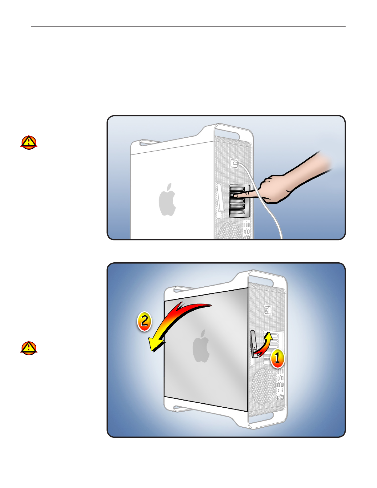
First Steps
Shut down computer.1
Wait 10 minutes.
2
Warning: Parts inside
computer can be very
hot. Allow computer
to cool down before
continuing.
Unplug all external 3
cables except power
cord.
Touch metal PCI cover 4
on back of computer.
Unplug power cord.5
Note: Follow these instructions carefully. Failure to do so could damage your equipment and
void its warranty.
Opening the
Computer
Hold side access 1
panel and lift latch on
back of computer.
Warning: Edges of
access panel and
enclosure can be
sharp. Be careful
when handling.
Remove access panel 2
and place it on at
surface covered by
soft, clean cloth.
© 2009 Apple Inc. All rights reserved.
073-1254 Rev. A 1
Page 2
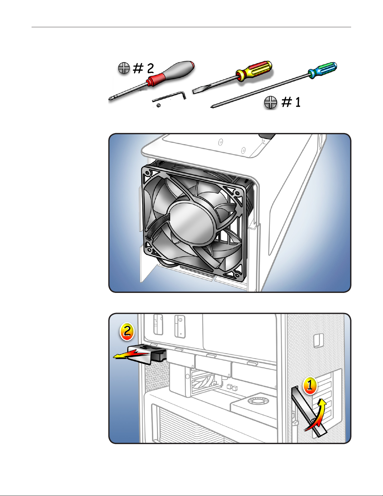
Required Tools
Phillips #2 screwdriver •
RIght-angle, 2.5 mm •
hex driver
Flatblade screwdriver•
Long-handled Phillips •
#1 screwdriver
Removing the
Installed Fans
Fans are installed in
processor cage. To access
fans, you must rst
remove:
Hard drive in far-left •
drive bay
Graphics card in slot 1•
Processor tray•
PCIe fan•
Processor cage•
Hard Drive
1 Make sure latch on
back panel is up, so
that drive is unlocked.
Pull hard drive out of 2
far-left drive bay.
© 2009 Apple Inc. All rights reserved.
073-1254 Rev. A 2
Page 3
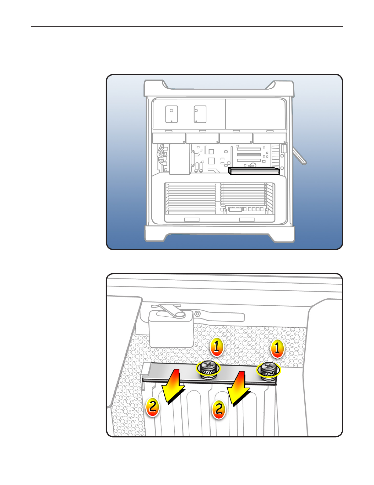
Graphics Card
3 Locate graphics card
in slot 1.
4 Using Phillips #1
screwdriver, loosen 2
captive screws
securing card’s
bracket to enclosure.
Remove bracket from 5
enclosure.
© 2009 Apple Inc. All rights reserved.
073-1254 Rev. A 3
Page 4
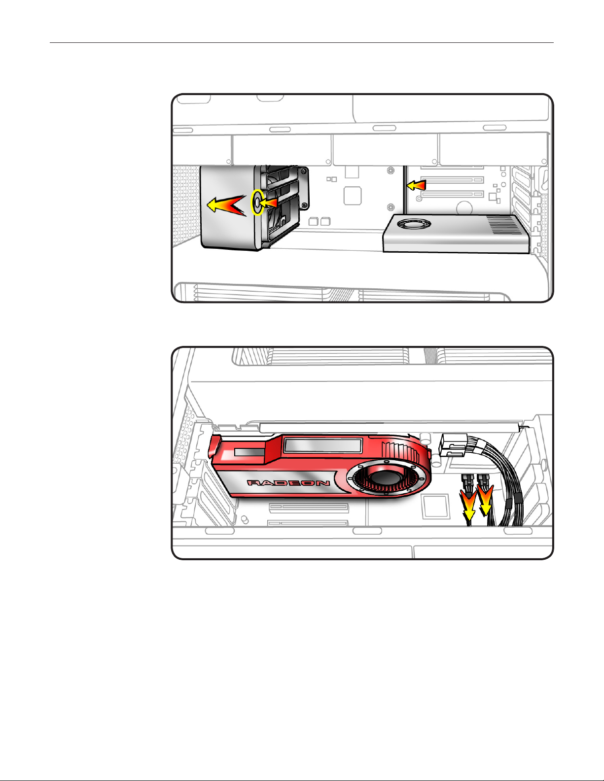
Note: Card is held in place
by retention bar. Following
two steps explain how to
release bar.
Press button on PCIe 6
fan.
Move fan to left, 7
which releases
retention bar.
Note: Some graphics
cards require 1 or 2
booster cables connecting
card to auxiliary power
connectors on backplane
board. If your card has
booster cables, disconnect
them from backplane
board.
© 2009 Apple Inc. All rights reserved.
073-1254 Rev. A 4
Page 5
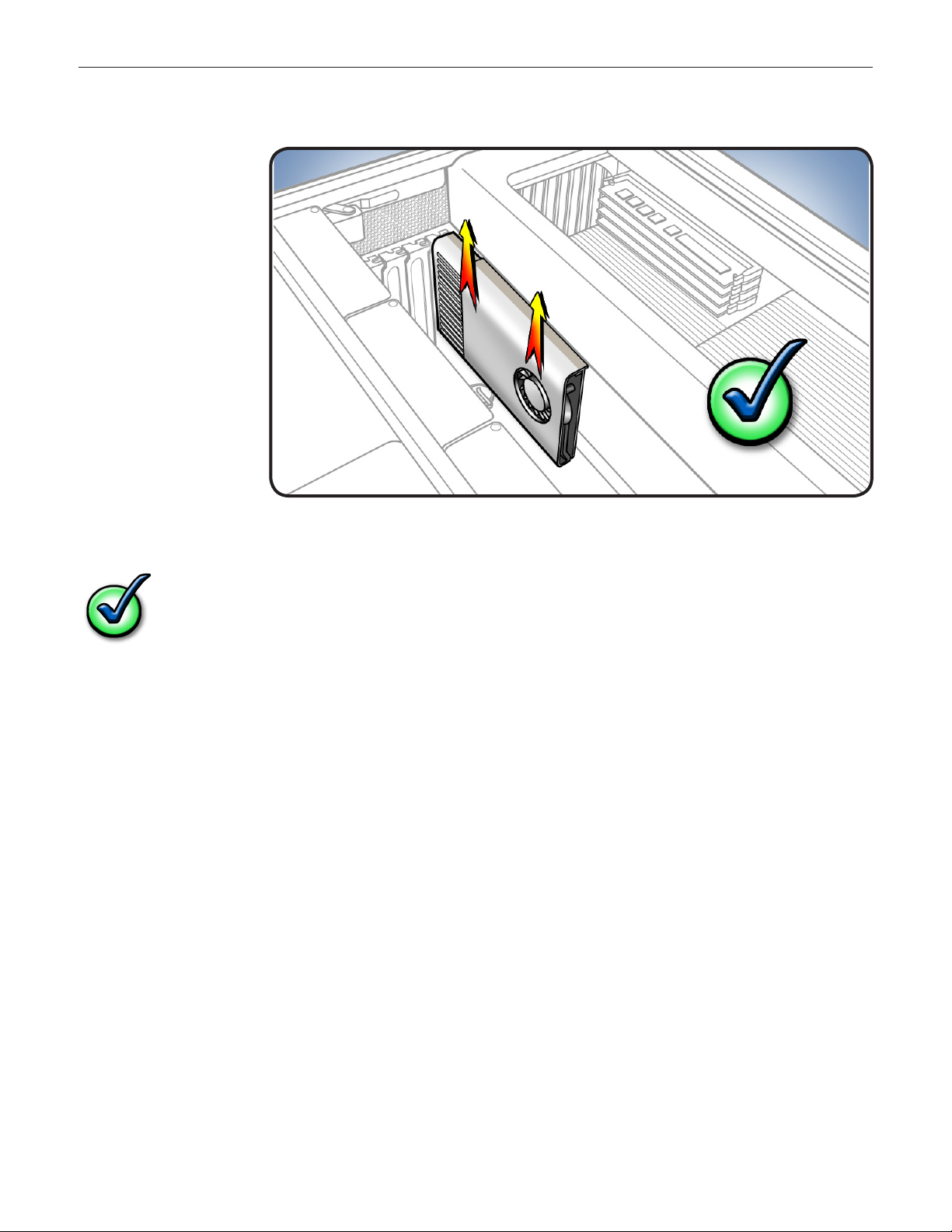
8 Holding card by top
corners, pull it up out
of slot.
Remove card from 9
computer.
Checklist for handling card:
When removing or installing card, handle it only by the edges. Do not touch its connectors •
or any components.
Don’t rock card from side to side; instead, lift card straight up from connecotr to remove it, •
and press card straight into slot to install it.
Don’t force card. If you meet a lot of resistance, pull card out. Check connector and slot for •
damage or obstructions, then try inserting card again.
Pull card gently to see if it is properly connected. If it resists and stays in place and its gold •
connectors are barely visible, card is connected.
© 2009 Apple Inc. All rights reserved.
073-1254 Rev. A 5
Page 6

Processor Tray
10 Locate processor tray.
11 Press down and
release 2 latches on
front of processor tray.
© 2009 Apple Inc. All rights reserved.
073-1254 Rev. A 6
Page 7

12 Holding tray by
latches, lift it out of
computer.
Place tray DIMM side 13
up on soft, clean
cloth.
PCIe Fan
14 Locate PCIe fan.
© 2009 Apple Inc. All rights reserved.
073-1254 Rev. A 7
Page 8

15 Remove 2 screws.
Slide fan up and out 16
of computer.
Processor Cage
17 Locate processor
cage.
© 2009 Apple Inc. All rights reserved.
073-1254 Rev. A 8
Page 9

18 Disconnect 3 cables
from logic board.
Using long-handled 19
Phillips #1 screwdriver,
loosen 6 captive
screws.
Rotate computer to 20
stand vertically. Using
2.5 mm hex driver,
remove 5 mushroomhead screws.
Note: Processor cage includes two fans, one at each end of cage. Before removing cage from
enclosure, you must release 2 latches on each fan and push fans partway into cage.
21 To release 2 latches
holding front fan to
cage, press down on
bottom of cage while
using atblade
screwdriver to release
latch from top of
cage.
Slide fan partway 22
into cage, so that fan
clears enclosure.
Repeat steps 4 and 5 23
for rear fan.
© 2009 Apple Inc. All rights reserved.
073-1254 Rev. A 9
Page 10

24 Lift cage out of
enclosure.
Processor Cage Fans
25 Locate processor cage
fans.
© 2009 Apple Inc. All rights reserved.
073-1254 Rev. A 10
Page 11

26 Release fan cables
from clips on bottom
of processor cage.
27 Release 4 latches on
front fan and slide fan
out of cage.
Note: Latch #4 is on
inside of cage.
Repeat above step for 28
rear fan.
© 2009 Apple Inc. All rights reserved.
073-1254 Rev. A 11
Page 12

Installing the
Replacement
Fans
I1 Position front fan in
cage.
Slide fan back until it 2
engages with the 4
latches.
Repeat above two 3
steps for rear fan.
4 Re-insert fan cables in
clips on bottom of
processor cage.
© 2009 Apple Inc. All rights reserved.
073-1254 Rev. A 12
Page 13

Processor Cage
Important: Before you re-
install cage into enclosure,
fans must be inserted
partway into cage.
5 Position cage in
enclosure.
Slide front and rear 6
fans into place, so
that they engage with
latches.
Replace and tighten 7
5 mushroom-head
screws.
Secure 8 6 captive
screws.
Reconnect 9 3 cables.
PCIe Fan
10 Slide fan into
enclosure so that fan
tabs engage with
slots on metal cage.
Press down until fan 11
clicks into place in
connector.
Replace 12 2 screws.
© 2009 Apple Inc. All rights reserved.
073-1254 Rev. A 13
Page 14

Processor Tray
Holding tray by 13
latches, lower it into
processor cage.
Make sure latches are 14
closed ush with front
of processor tray.
Graphics Card
15 Reinstall graphics card
in slot 1.
Note: Align card’s
connector with
expansion slot and
press down until
connector is inserted
all the way into slot.
If installing a 12-inch
card, make sure card
engages correct slot
in PCIe card guide.
If card includes 16
booster cables,
reconnect cables.
17 Slide PCIe fan to the
right to lock card in
place.
Replace PCI bracket 18
and tighten screws.
Note: Slide bracket
under circled tab.
© 2009 Apple Inc. All rights reserved.
073-1254 Rev. A 14
Page 15

Hard Drive
19 Replace hard drive in
far-left drive bay.
Closing the
Computer
Replace access panel.
1
Note: Make sure
latch is up before you
replace panel. If latch
is down, panel will
not seat correctly.
Push latch down 2
to close and secure
access panel.
Warning: Never turn
on computer unless
all its internal and
external parts are in
place and it is closed.
Operating computer
when open or missing
parts can cause
damage or injury.
Apple Inc.
© 2009 Apple Inc. All rights reserved.
This document is protected under U.S. Copyright Law and International Treaties, and no part of this
document may be reproduced in any form without written permission from Apple.
Apple is not responsible for typographical, printing, or inadvertent errors.
Apple Inc.
1 Innite Loop
Cupertino, CA 95014-2084 USA
+ 1 408 996 1010
www.apple.com
Apple, the Apple logo, and Mac are trademarks of Apple Inc., registered in the U.S. and other countries.
© 2009 Apple Inc. All rights reserved.
073-1254 Rev. A 15
 Loading...