

Page 1
K
Service Source
Power Mac G4/
Macintosh Server G4
Power Mac G4 (AGP Graphics/Gigabit Ethernet/Digital Audio/
QuickSilver/QuickSilver 2002/QuickSIlver 2002ED),
Power Mac G4 (PCI Graphics),
Macintosh Server G4
Page 2
K
Service Source
Basics
Power Mac G4/
Macintosh Server G4
© 2002 Apple Computer, Inc. All rights reserved.
Page 3
Basics Product Description - 1
Overview
|
Product Description
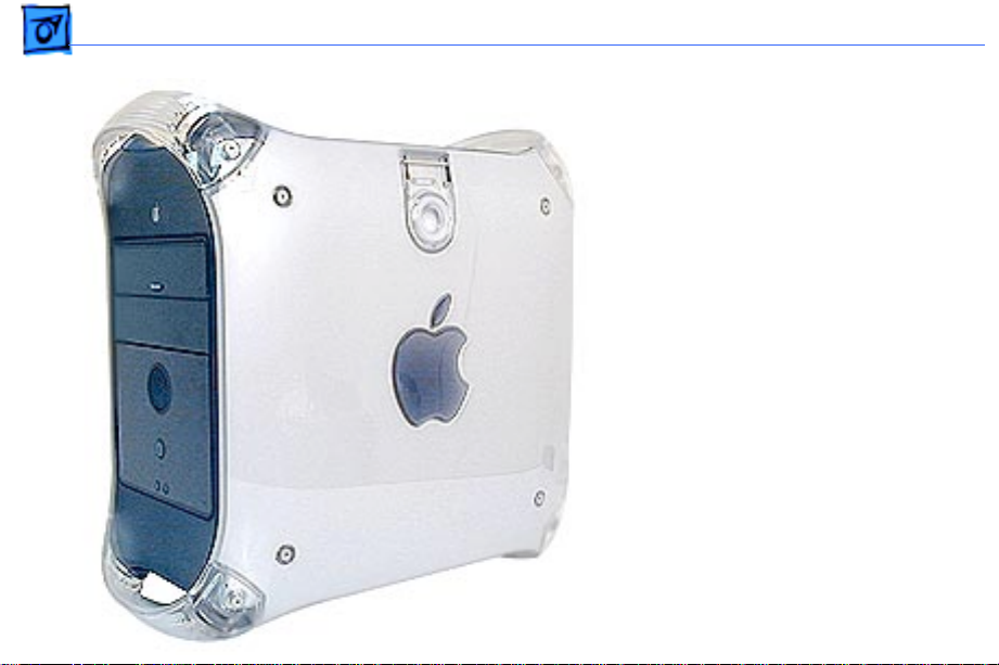
The Power Mac G4 is the
first Power Mac computer
based on the PowerPC G4
processor. Some
configurations also include
support for wireless
networking, dual-channel
USB, Gigabit Ethernet, dual
processing, digital audio,
and a wake/sleep power
management feature.
Page 4
Basics Identifying Versions of the Power Mac G4 - 2
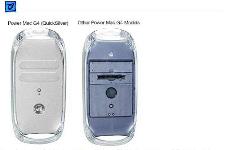
Identifying Versions of the Power Mac G4
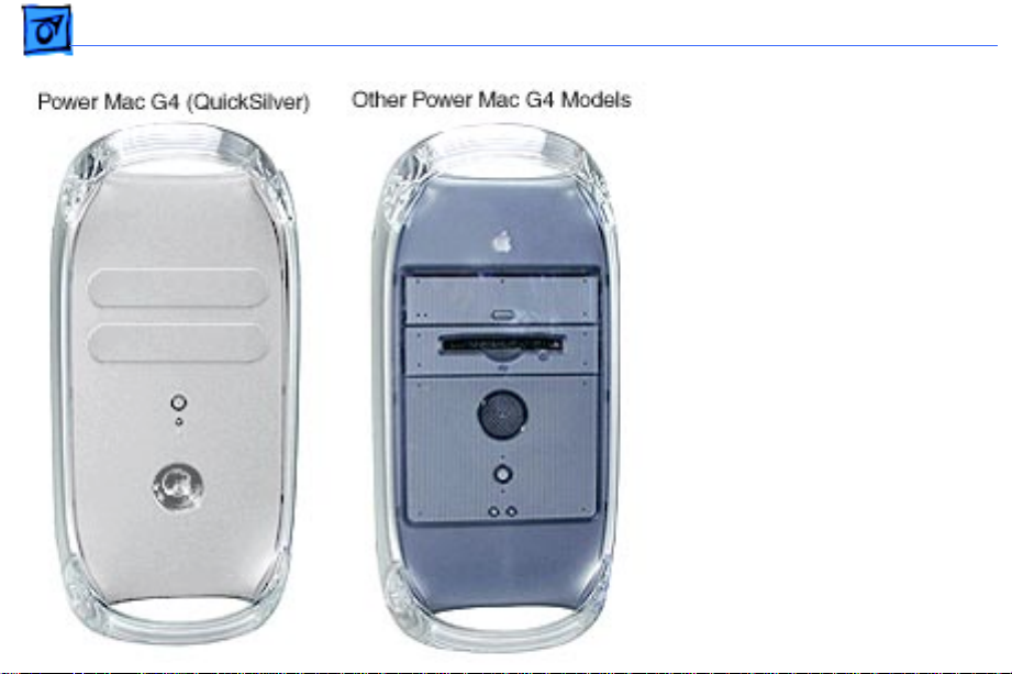
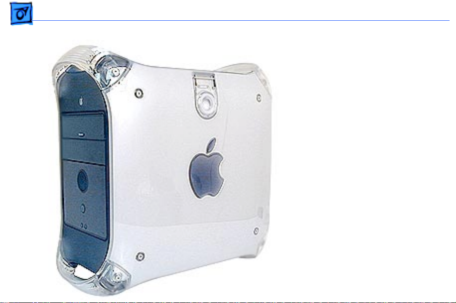
There are six models of
Power Mac G4 computers:
AGP Graphics, PCI Graphics,
Gigabit Ethernet, Digital
Audio, QuickSilver, and
QuickSilver 2002.
Power Mac G4 (QuickSilver
and QuickSilver 2002)
computers are easy to
identify. Unlike other Power
Mac G4 models, these models
have a silver-colored case.
They also have a recessed
speaker on the front panel.
Page 5
Basics New Technologies - 3
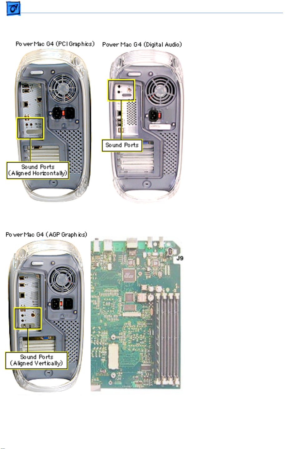
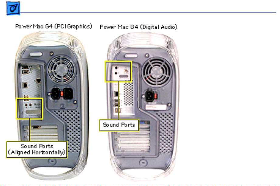
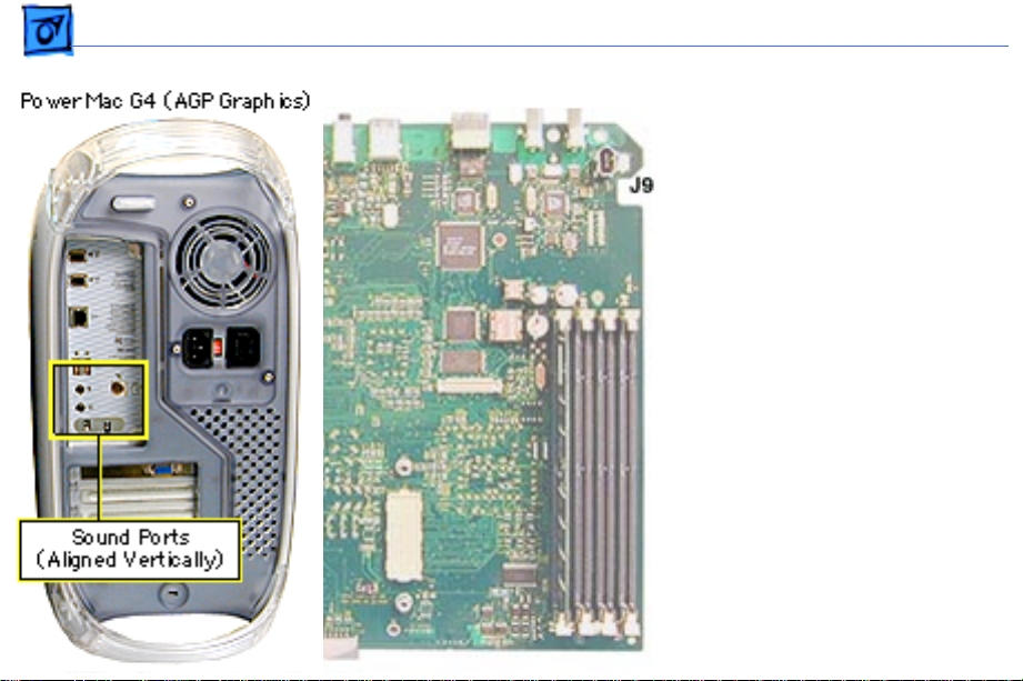
To identify the other Power
Mac G4 models, check the
I/O panel at the back of the
computer. The sound ports
align horizontally in the
lower half of the I/O panel
on PCI Graphics models and
vertically on AGP Graphics/
Gigabit Ethernet models. On
Digital Audio models, the
sound ports are in the upper
half of the I/O panel. In
addition, Digital Audio
models include four
expansion slots, instead of
three slots on PCI/AGP
Graphics/Gigabit Ethernet
models.
To further distinguish
Gigabit Ethernet models
from AGP Graphics models,
check the logic boards. AGP
Graphics boards include an
internal FireWire connector
at J9; Gigabit Ethernet
boards do not include the
connector.
New Technologies
While the Power Mac G4
family of computers all use
the innovative PowerPC G4
processor, they also include
a range of other new hardware and architectures. For
information on the latest
technolgies, check the Apple
Knowledge Base.
Page 6

Basics Standard Configurations - 4
Features
|
Standard Configurations
Processor
• 350 MHz,400 MHz, 450 MHz, 466 MHz, 500 MHz, 533
MHz, 733 MHz, 800 MHz, 867 MHz, 933 MHz, or 1 GHz
PowerPC G4 processor; dual processors on some
configurations
• Velocity Engine vector processing unit with 162
integrated Single Instruction Multiple Data (SIMD)
instructions
• Full 128-bit internal memory data paths
• Powerful floating-point unit supporting single-cycle,
double-precision calculations
• Data stream prefetching operations supporting four
Page 7

Basics Standard Configurations - 5
simultaneous 32-bit data streams
• L2 or L3 cache
• 100-MHz system bus (PCI Graphics/AGP Graphics/
Gigabit Ethernet) or 133-MHz system bus
(QuickSilvers/Digital Audio)
Memory
• 64, 128, 256, or 512 MB of PC-100 SDRAM (PCI
Graphics/AGP Graphics/Gigabit Ethernet) or
64, 128, 256, or 512 MB of PC-133 SDRAM
(QuickSilvers/Digital Audio)
• Four DIMM slots (PCI Graphics/AGP Graphics/Gigabit
Ethernet) or three DIMM slots (QuickSilvers/Digital
Audio)
Page 8

Basics Standard Configurations - 6
Storage
• One of the following hard drives: 10, 13, 20, 27, 30,
40, 60, or 80 GB Ultra ATA
• One of the following optical drives:
– CD-ROM drive
– CD-RW drive
– DVD-ROM drive
– DVD-RAM drive
– DVD-R/CD-RW drive
– DVD/CD-RW drive
• Optional 100 or 250 MB Zip drive
• Three 3.5-inch hard drive expansion bays
– One ATA drive preinstalled in standard configurations
– Support for up to two internal ATA drives
– Support for up to three internal SCSI drives
Page 9

Basics Standard Configurations - 7
Graphics Support
• Video card installed in a dedicated graphics slot (either a
PCI slot or an AGP slot)
• Support for up to 1,600 by 1,200 pixel resolution at 32
bits per pixel and up to 85-Hz refresh rate
• 15-pin mini D-Sub VGA connector
• ADC connector for digital flat-panel display (not
available on PCI Graphics computers)
• Support for independent video output to two monitors
(with NVIDIA TwinView video card)
Page 10

Basics Standard Configurations - 8
Electrical Requirements and Agency Approvals
• Line voltage: 115V AC (90V to 132V AC) or 230V AC
(180V to 264V AC)
• Frequency: 47 to 63 Hz, single phase
• Maximum continuous power (not including display):
200W EPA ENERGY STAR and Blue Angel compliant (some
configurations)
Environmental Requirements
• Operating temperature: 50° to 95° F (10° to 35° C)
• Storage temperature: -40° to 116° F (-40° to 47° C)
• Relative humidity: 5% to 95% noncondensing
• Maximum altitude: 10,000 feet (3,048 m)
Page 11

Basics Standard Configurations - 9
Size and Weight
• Height: 17.0 inches (43.2 cm)
• Width: 8.9 inches (22.6 cm)
• Depth: 18.4 inches (46.7 cm)
• Weight: 30.0 pounds (13.6 kg)
Storage devices and interfaces vary among
Note:
configurations.
Page 12

Basics Configure-to-Order Options - 10
Configure-to-Order Options
The configure-to-order options are available from the
Apple Store. For more information, view the options online
at http://store.apple.com.
Page 13
Basics Power Mac G4 (AGP Graphics/Gigabit Ethernet) Views - 11
Views
|
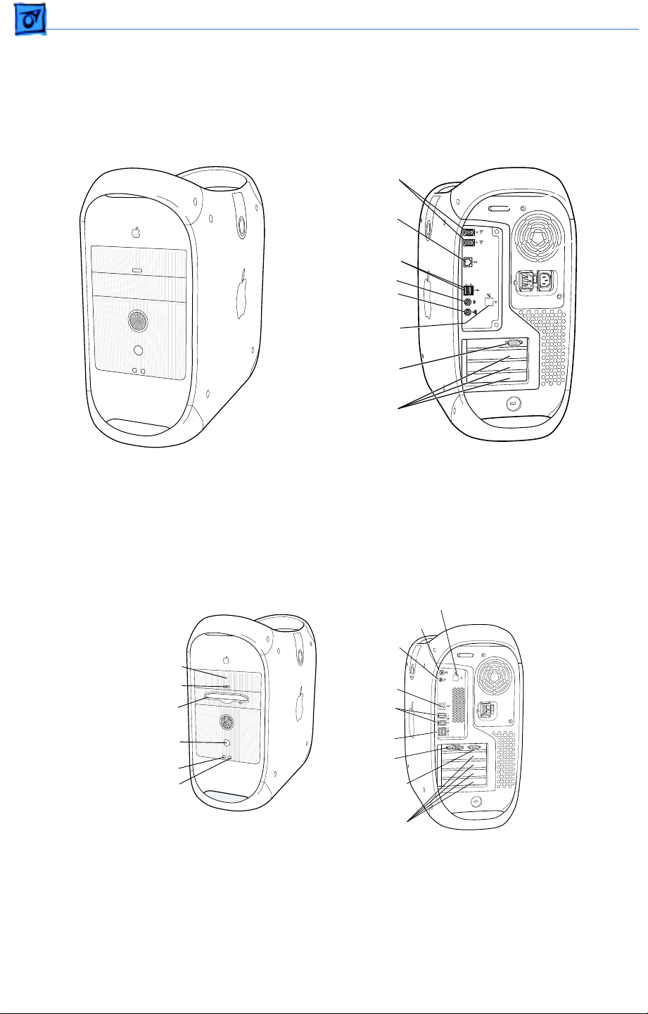
Power Mac G4 (AGP Graphics/Gigabit Ethernet) Views
FireWire Ports (2)
Ethernet Port
USB Ports (2)
Sound Input Port
Sound Output Port
Internal
Modem Port
(Optional)
VGA Monitor Port
(Slot 1: AGP)
Access Covers for
Expansion Slots
Power Mac G4 (Digital Audio) Views
CD or DVD Drive
Open Button
Zip Drive
(optional)
Power Button/
Power-on Light
Reset Button
Programmer’s
Button
VGA Monitor Port
Internal Modem Port
(Optional)
Headphone Jack
Digital Audio
Jack
Ethernet Port
FireWire
Ports (2)
USB Ports (2)
ADC
Monitor Port
(Slot 1: AGP)
Access Covers
Page 14
Basics Power Mac G4 (AGP Graphics/Gigabit Ethernet) Internal Locator - 12
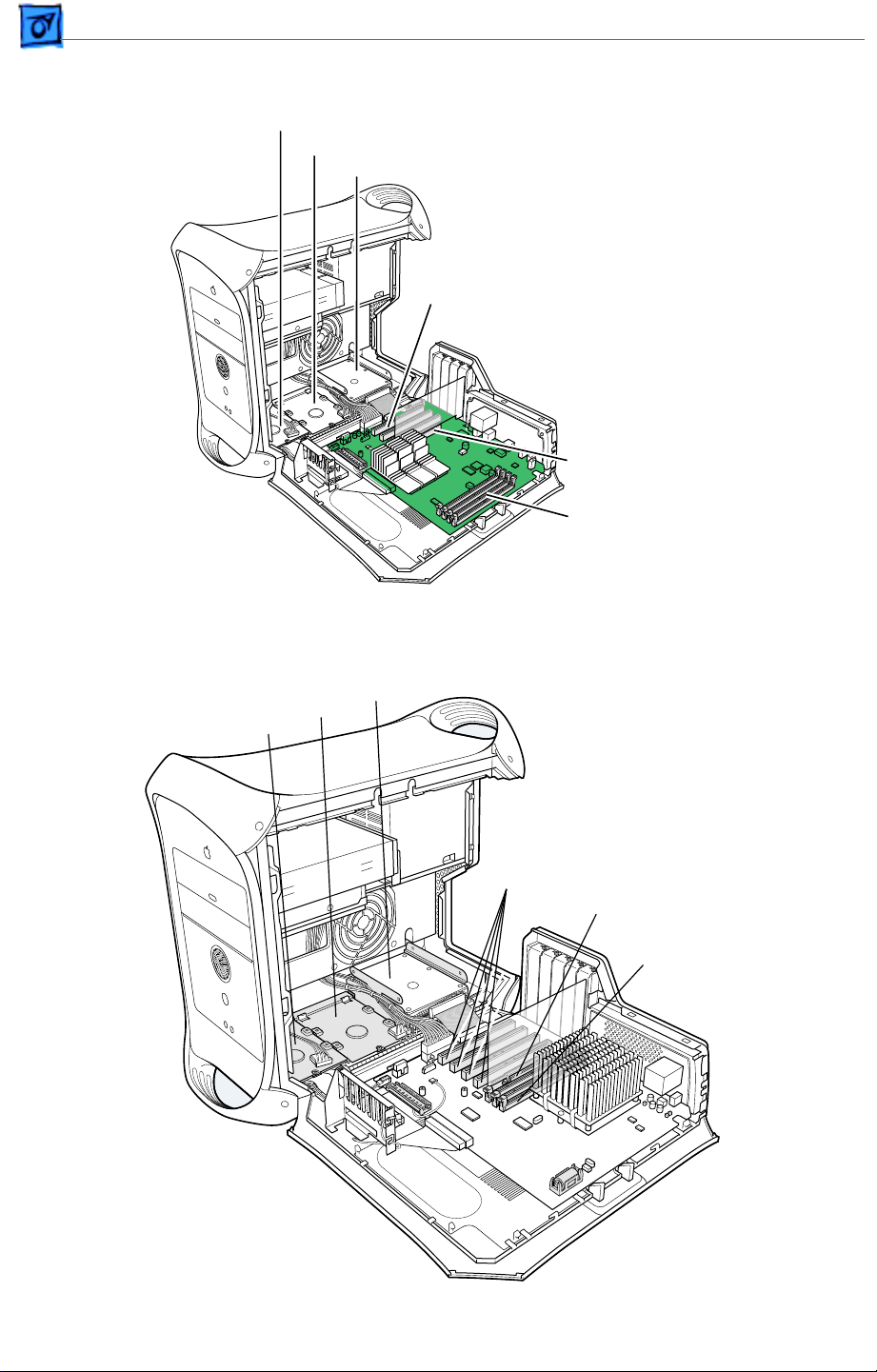
Power Mac G4 (AGP Graphics/Gigabit Ethernet) Internal Locator
Drive Bay 1
Drive Bay 2
Drive Bay 3
PCI Slots (3)
AGP Slot
SDRAM
Slots (4)
Power Mac G4 (QuickSilvers/Digital Audio) Internal Locator
Drive Bay 3
Drive Bay 2
Drive Bay 1
PCI Slots (4)
AGP Slot
SDRAM Slots (3)
Page 15
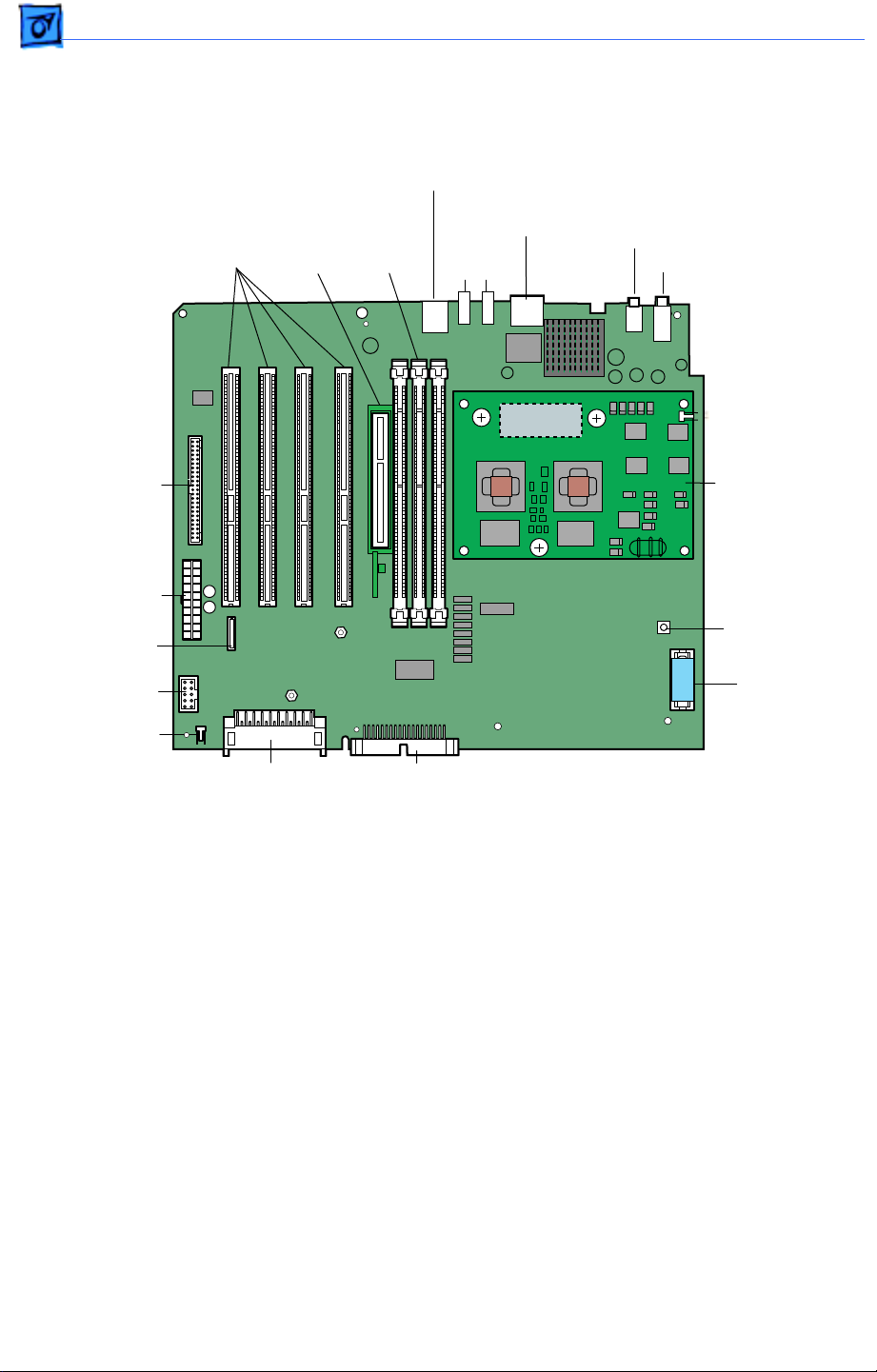
Basics PowerMac G4 (AGP Graphics/Gigabit Ethernet) Logic Boards - 13
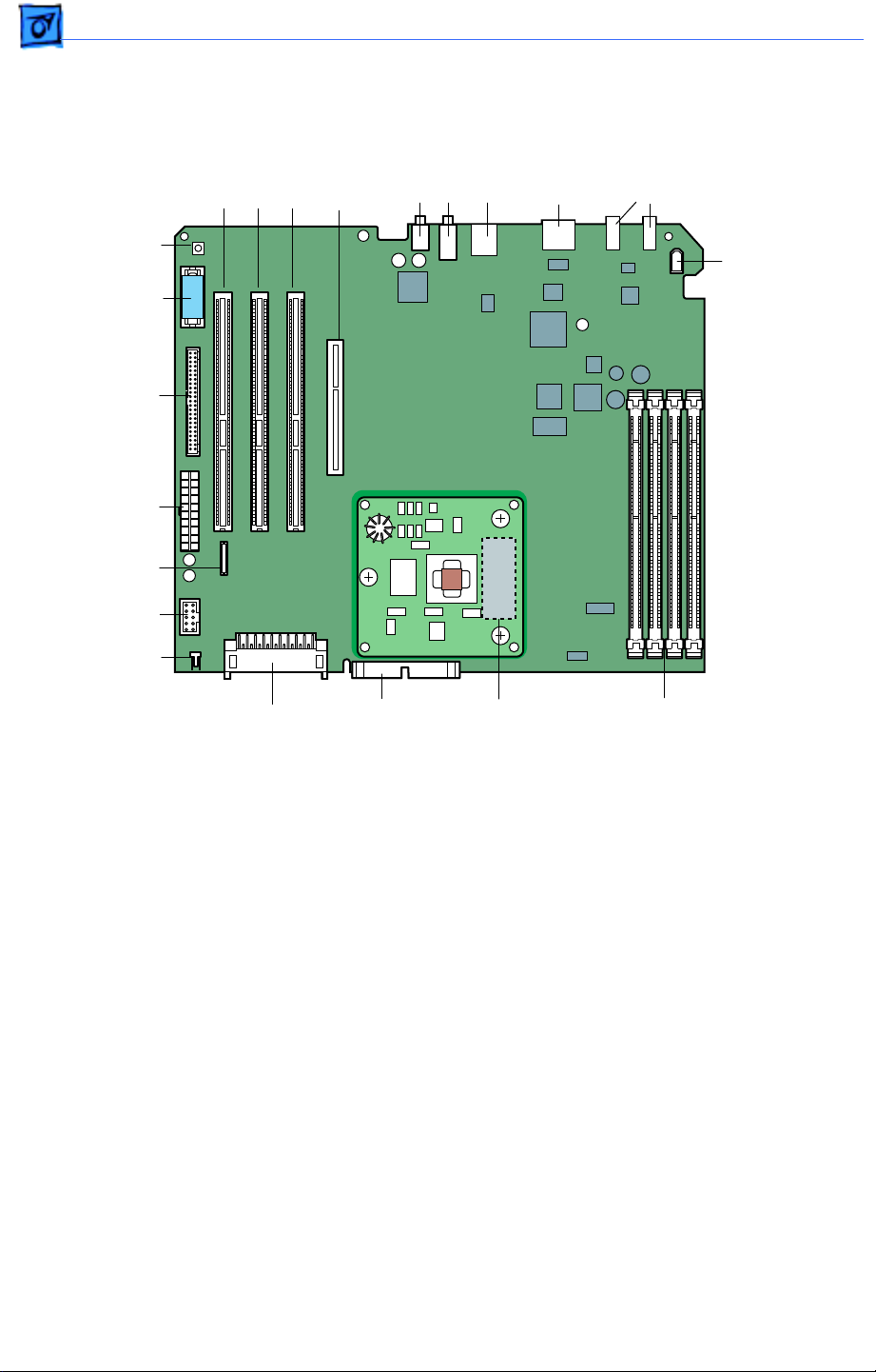
PowerMac G4 (AGP Graphics/Gigabit Ethernet) Logic Boards
USB
FireWire
Ports (2)
PCI Slots
Monitor
Card Slot
Ports
A & B
Sound In
Sound Out
Ethernet
Connector
PMU Button
Battery
Ultra ATA
Connector
Power
Modem
Connector
Front Panel
Board
Speaker
Internal
FireWire
Port
(not included
on Gigabit
models)
AirPort
Connector
IDE
Connector
Processor
Plug-In
Slot
SDRAM
DIMM Slots
Page 16
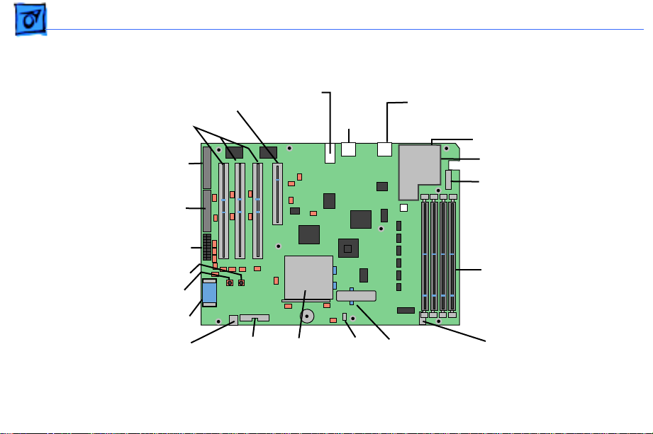
Basics PowerMac G4 (QuickSilvers/Digital Audio) Logic Board - 14
PowerMac G4 (QuickSilvers/Digital Audio) Logic Board
USB
Ports
A & B
Ethernet
Connector
Digital Audio Jack
Headphone Jack
PCI
Slots
Monitor
Card
Slot
SDRAM
DIMM
Slots
FireWire
Ports (2)
Ultra A TA
Connector
Power
Modem
Connector
Front Panel
Board
Speaker
AirPort
Connector
Single or Dual
Processor
PMU Button
Battery
IDE
Connector
Page 17
Basics Power Mac G4 (PCI Graphics) Logic Board - 15
Power Mac G4 (PCI Graphics) Logic Board
Monitor Card Slot
PCI Slots
J1 ATA-3
(CD/DVD-ROM
and Zip Drive
J15 Ultra DMA/33
(ATA Drives)
J23 Power
S5 Power Button
S4 Cuda Button
Battery
J8 CD Audio
Sound In &
Sound Out
J31
Front Panel
Board
Ports
Processor
Plug-In
Slot
USB
Ports
A & B
J34
Speaker
Ethernet Connector
Firewire Ports (2)
Firewire Card
Modem
Connector
SDRAM
DIMM Slots
J25
Jumper Block
(w/sticker)
J2 Firewire
Power
Page 18

Basics Strategy and Ordering - 16
Repair Strategy/Warranty
|
Strategy and Ordering
Service Power Mac G4 computers through module exchange
and parts replacement.
Apple-authorized service providers planning to support the
computer systems covered in this manual may purchase
service modules and parts to develop servicing capability. To
order parts, use the AppleOrder (U.S. only) or ARIS (Canada
only) system and refer to the Power Mac G4 Service Price
Pages.
Large businesses, universities, and K-12 accounts must
provide a purchase order on all transactions, including
orders placed through the AppleOrder (U.S. only) or ARIS
(Canada only) system.
Page 19

Basics Strategy and Ordering - 17
USA Ordering
U.S. service providers not enrolled in AppleOrder may fax
their orders to Service Provider Support (512-908-
8125) or mail them to:
Apple Computer, Inc.
Service Provider Support / MS 212-SPS
2323 Ridgepoint Drive
Austin, TX 78754
For U.S. inquiries, please call Service Provider Support
(800-919-2775, option #1).
Page 20

Basics Warranty - 1 8
Canadian Ordering
Canadian service providers not enrolled in ARIS may fax
their orders to Service Provider Support in Canada (800903-5284). For Canadian inquiries, please call Service
Provider Support (800-217-9517).
Warranty
U.S. Only
Power Mac G4 computers are covered under the Apple OneYear Limited Warranty. The AppleCare Protection Plan is
also available for these products. Service providers are
reimbursed for warranty and AppleCare Protection Plan
repairs. For pricing information, refer to Service Price
Pages.
Page 21

Basics Warranty - 1 9
Canada Only
Power Mac G4 computers are covered under the Apple OneYear Limited Warranty. The AppleCare Protecion Plan is
also available for these products. Service providers are
reimbursed for warranty and AppleCare Protection Plan
repairs. For pricing information, refer to Service Price
Pages.
Page 22

K
Service Source
T ak e Apart
Power Mac G4 / Macintosh
Server G4
© 2002 Apple Computer, Inc. All rights reserved.
Page 23
Take Apart Identifying Models of the Power Mac G4 - 1
General
Identifying Models of the Power Mac G4
There are six models of
Power Mac G4 computers:
AGP Graphics, PCI Graphics,
Gigabit Ethernet, Digital
Audio, QuickSilver, and
QuickSilver 2002.
Power Mac G4 (QuickSilver
and QuickSilver 2002)
computers are easy to
identify. Unlike other Power
Mac G4 models, these models
Page 24
Take Apart Identifying Models of the Power Mac G4 - 2
have a silver-colored case.
They also have a recessed
speaker on the front panel.
To identify the other Power
Mac G4 models, check the I/
O panel at the back of the
computer. The sound ports
align horizontally in the
lower half of the I/O panel
on PCI Graphics models and
vertically on AGP Graphics/
Gigabit Ethernet models. On
Digital Audio models, the
sound ports are in the upper
half of the I/O panel. In
addition, Digital Audio
models include four
Page 25
Take Apart Identifying Models of the Power Mac G4 - 3
expansion slots, instead of
three slots on PCI/AGP
Graphics/Gigabit Ethernet
models.
To further distinguish
Gigabit Ethernet models
from AGP Graphics models,
check the logic boards. AGP
Graphics boards include an
internal FireWire connector
at J9; Gigabit Ethernet
boards do not.
Note:
Except where indicated, the following procedures apply to all six
models.
Page 26

Take Apart Tools - 4
Tools
• Flatblade screwdriver
• Phillips screwdriver
• Allen wrench (2.5 mm)
to remove the power
supply, side panels, top
and rear handles, and
front and rear supports
• Jeweler’s screwdriver to
remove the I/O panel
cover and antenna
• Needlenose pliers to
remove the right and left
side panels
• ESD mat
Page 27
Take Apart Opening the Computer - 5
Procedures
Opening the Computer
No preliminary steps are
required before you begin
this procedure.
Page 28
Take Apart Opening the Computer - 6
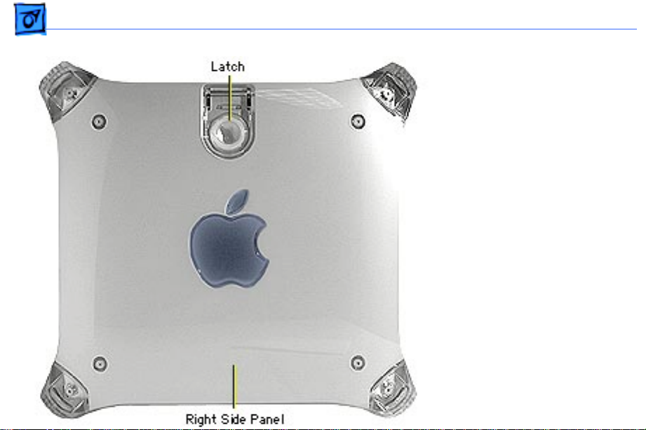
1. Lift the latch to unlock
the right side access
panel.
Note:
Make sure the
security bar is in the
unlock position.
2. Gently lower the side
panel onto a clean, ESDsafe mat to avoid
scratching the case.
Lower the side panel
until it lies flat.
Page 29
Take Apart Video Card - 7
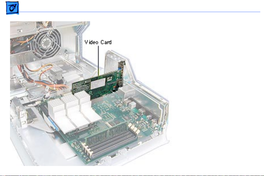
Video Card
Before you begin, do the
following:
• Open the side access
panel.
• Remove the external video
cable.
Note:
The AGP video card is
always installed in slot 1
(short slot). The DVD
decoder module is used only
in Power Mac G4 (PCI
Graphics) computers.
Page 30
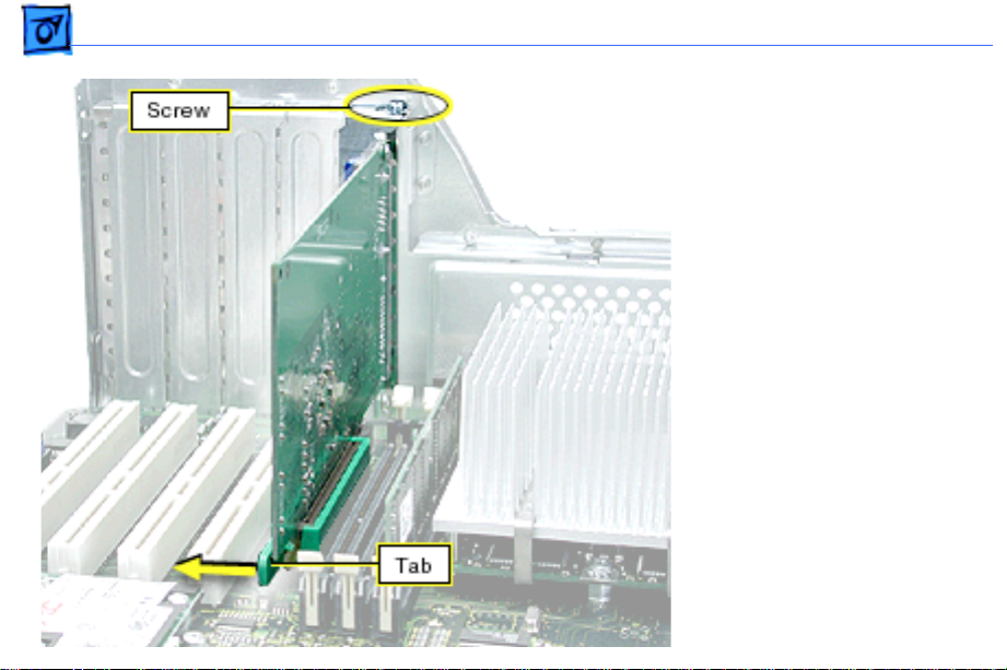
Take Apart Video Card - 8
1. Remove the video card
mounting screw.
2. If a plastic clip sur-
rounds the video card
connector, gently p
back the clip’s tab to
release the card. Then
gently pull the card up, and
remove it from the AGP
slot.
3. Power Mac G4 (PCI
Graphics): If you are
replacing the DVD
decoder module, pull it
straight off the card.
ull
Page 31

Take Apart Video Card - 9
Replacement Note: If the
replacement card does not
have a fence already installed,
attach the fence enclosed in
the box. Using a Phillips
screwdriver, install the two
small Phillips screws on either
side of the ADC connector and
the two large Phillips screws on
the fence side tabs. Using
pliers, install the two jack-nut
screws on either side of the
VGA connector.
Page 32

Take Apart Modem, AGP Graphics/Gigabit Ethernet/Digital Audio/QuickSilvers - 10
Modem, A GP Graphics/Gigabit Ethernet/Digital A udio/ QuickSilvers
Note:
The Power Mac G4
(AGP Graphics/Gigabit
Ethernet/Digital Audio/
QuickSilver/QuickSilver
2002) modem requires a
modem filter; the two are
separate parts. To remove
the modem, you do not need
to remove the modem filter.
Before you begin, open the
side access panel.
Page 33

Take Apart Modem, AGP Graphics/Gigabit Ethernet/Digital Audio/QuickSilvers - 11
Warning:
disconnecting or connecting
the modem to the J27
connector on the logic board.
Bent pins in the J27
connector could cause a
short in the logic board.
1. Remove the two modem
2. Lift the modem straight
Use care when
mounting screws.
up to disconnect it from
the logic board.
Page 34

Take Apart Modem, AGP Graphics/Gigabit Ethernet/Digital Audio/QuickSilvers - 12
3. Disconnect the modem
filter cable from the
modem.
4. Remove the modem from
the computer.
Replacement Note:
replacing an international
modem, use the Modem
Country Selector utility to
set the modem to the correct
country.
After
Page 35

Take Apart Modem Filter, AGP Graphics/Gigabit Ethernet/Digital Audio/QuickSilvers
Modem Filter, AGP Graphics/Gigabit Ethernet/Digital A udio/ QuickSilvers
Before you begin, do the
following:
• Open the side access
panel.
• Remove the logic board.
Page 36

Take Apart Modem Filter, AGP Graphics/Gigabit Ethernet/Digital Audio/QuickSilvers
1. Remove the screw that
secures the modem filter
to the I/O panel.
Page 37

Take Apart Modem Filter, AGP Graphics/Gigabit Ethernet/Digital Audio/QuickSilvers
2. Free the modem filter
cable from the chassis
guides and remove the
modem filter from the
computer.
Page 38

Take Apart Modem, PCI Graphics - 16
Modem, PCI Graphics
Before you begin, open the
side access panel.
Warning:
disconnecting or connecting
the modem to the J27
connector on the logic board.
Bent pins in the J27
connector could cause a
short in the logic board.
Use care when
Page 39

Take Apart Modem, PCI Graphics - 17
1. Remove the screw
(located next to the
modem port) that
secures the modem to the
I/O panel.
2. Remove the screw that
secures the modem leg
standoff to the logic
board.
Page 40

Take Apart Modem, PCI Graphics - 18
3. Carefully disconnect the
flexible modem cable
from the logic board.
Important:
cable is very fragile.
4. Gently lift up the modem
to remove it from the
logic board.
Note:
replacing the modem,
continue with the Take
Apart procedures to
remove the modem from
the bottom modem shield.
The modem
If you are
Page 41

Take Apart Modem, PCI Graphics - 19
5. With a jeweler’s
screwdriver, pry up the
metal tabs on the top
shield.
6. Carefully disconnect the
flexible modem cable
from the modem board.
Page 42

Take Apart Modem, PCI Graphics - 20
7. Remove the screw
securing the modem to
the bottom shield.
Page 43

Take Apart Modem, PCI Graphics - 21
8.
Note:
There are two tiny
metal tabs on the inside
of the bottom shield. The
modem rests on these
tabs so it does not make
contact with the bottom
shield.
With a needlenose
pliers, pinch the tiny
metal tabs flat so the
modem board can be
removed from the bottom
shield.
Page 44

Take Apart Modem, PCI Graphics - 22
9. Carefully spread the
sides of the bottom shield
out just enough so the
modem clears the tabs,
and starts to fall out of
the bottom shield.
10.Carefully remove the
modem from the bottom
shield.
Replacement Note:
replacing an international
modem, use the Modem
Country Selector utility to
set the modem to the correct
country.
After
Page 45

Take Apart FireWire Board, PCI Graphics - 23
FireWire Board, PCI Graphics
Note:
The FireWire board is
used only in Power Mac G4
(PCI Graphics) computers.
Power Mac G4 (AGP
Graphics/Gigabit Ethernet/
Digital Audio/QuickSilver/
QuickSilver 2002)
computers have FireWire
built into the logic board.
Before you begin, do the
following:
• Open the side access
panel.
• Remove the modem.
Page 46

Take Apart FireWire Board, PCI Graphics - 24
1. Remove the screw
securing the FireWire
board to the I/O panel.
2. Remove the screw that
secures the FireWire
board to the metal
standoff.
3. Disconnect the FireWire
cable, the short 3-pin
cable from the back of
the FireWire board or
logic board.
4. Gently lift up the
FireWire board to
remove it from the logic
board connector.
Page 47

Take Apart Processor Fan, Power Mac G4 (QuickSilvers) - 25
Processor Fan, Power Mac G4 (QuickSilvers)
Before you begin, open the
side access panel.
Page 48

Take Apart Processor Fan, Power Mac G4 (QuickSilvers) - 26
1. Disconnect the processor
fan cable from the logic
board.
2. Remove the two fan
mounting screws.
3. Lift the processor fan
out of the computer.
Page 49

Take Apart Processor Module, Power Mac G4 (QuickSilvers) - 27
Processor Module, Power Mac G4 (QuickSilvers)
Before you begin, do the
following:
• Open the side access
panel.
• Remove the processor fan.
±
Warning:
covering the processor may
be hot. If the computer has
been recently operating,
allow it to cool down before
performing this procedure.
The heatsink
Page 50

Take Apart Processor Module, Power Mac G4 (QuickSilvers) - 28
1. For single processors:
Release the right heatsink clip by pressing
down on the top of the
clip with one finger
while using a small
flatblade screwdriver to
lift up and out on the
clip’s front tab. Repeat
for the left heatsink clip.
Page 51

Take Apart Processor Module, Power Mac G4 (QuickSilvers) - 29
2. For dual processors:
Release the right heatsink clip by pressing
down on the top of the
clip with a screwdriver
while using a second
flatblade screwdriver to
lift up and out on the
clip’s front tab. Repeat
for the left heatsink clip.
±
Warning:
when pressing down on
the top of the clip. Too
much pressure can cause
the screwdriver to slip
and damage the logic
board.
Be careful
Page 52

Take Apart Processor Module, Power Mac G4 (QuickSilvers) - 30
3. Remove both clips and
lift the heatsink off the
processor module.
±
Warning:
removing the heatsink,
be careful not to bend the
processor module
beneath it.
When
Page 53

Take Apart Processor Module, Power Mac G4 (QuickSilvers) - 31
±
Warning:
that the computer is turned
off before performing this
procedure. The screw in the
bottom left circle of the
illustration conducts 12 V
and could spark if grounded
while the computer is on.
4. Remove the four
mounting screws.
Double-check
Page 54

Take Apart Processor Module, Power Mac G4 (QuickSilvers) - 32
5. To disconnect the
processor from the logic
board, hold it by the long
edges, gently rock the
processor right to left,
and lift straight up.
±
Warning:
module as shown when
removing or installing it
to avoid bending the
processor connector
pins.
Hold the
Replacement Note:
replacing the processor
module, tighten all screws
snugly, but not so tightly as
to damage the module. If the
When
Page 55

Take Apart Processor Module, Power Mac G4 (QuickSilvers) - 33
conducting screw is loose,
arcing can occur, damaging
the processor.
Important:
installing a new processor,
use the screw included in the
processor box. Install the
screw in the screw hole
exposed by the heatsink, as
shown in the illustration. Be
sure to tighten the screw
snugly, but do not
overtighten.
Note:
be discarded.
If you are
The old screw should
Page 56

Take Apart Processor Module, Power Mac G4 (QuickSilvers) - 34
Important:
replacing the processor
module, you must also
transfer the replacement
module’s connector cover to
the connector on the original
module before returning it
to Apple.
±
Warning:
reinstall the heatsink after
replacing or reinstalling the
processor module. Operating
the computer without the
heatsink in place will
destroy the processor.
If you are
Be sure to
Page 57

Take Apart Processor Module, AGP Graphics/Gigabit Ethernet/Digital Audio - 35
Processor Module, A GP Graphics/Gigabit Ethernet/Digital A udio
Before you begin, open the
side access panel.
±
Warning:
covering the processor may
be hot. If the computer has
been recently operating,
allow it to cool down before
performing this procedure.
The heatsink
Page 58

Take Apart Processor Module, AGP Graphics/Gigabit Ethernet/Digital Audio - 36
1. While pressing down on
the top of the heatsink
clip, use a small
flatblade screwdriver to
lift up and out on the
front tab of the clip to
release it.
2. Remove the heatsink clip
and lift the heatsink off
the processor module.
±
Warning:
removing the heatsink,
be careful not to bend the
processor module
beneath it.
When
Page 59

Take Apart Processor Module, AGP Graphics/Gigabit Ethernet/Digital Audio - 37
3. Remove the processor
mounting screws.
4. To disconnect the
processor from the logic
board, hold it by the
edges nearest the two
opposing screw holes (on
either side of the
connector), gently rock
the processor right to
left, and lift straight up.
±
Warning:
module as shown when
removing or installing it
to avoid bending the
processor connector
pins.
Hold the
Page 60

Take Apart Processor Module, AGP Graphics/Gigabit Ethernet/Digital Audio - 38
Important:
replacing the processor
module, you must also
transfer the replacement
module’s connector cover to
the connector on the original
module before returning it
to Apple. Make sure the hole
in the cover aligns with pin
one (marked by a white V)
on the connector.
If you are
Page 61

Take Apart Processor Module, PCI Graphics - 39
Processor Module, PCI Graphics
Before you begin, open the
side access panel.
Note:
The Power Mac G4
(PCI Graphics) processor
requires a jumper installed
at J25 on the logic board.
Page 62

Take Apart Processor Module, PCI Graphics - 40
1. Remove the screw that
attaches the heatsink
ground wire to the logic
board.
±
Warning:
may be hot to the touch. If
the computer has been
operating, allow it to cool
down before continuing.
2. While pressing down on
the top of the heatsink
clip, use a small
flatblade screwdriver to
release the clip by
lifting up and out on its
center front tab.
The heatsink
Page 63

Take Apart Processor Module, PCI Graphics - 41
3. Remove the heatsink clip
and lift the heatsink off
the processor module.
4. Lift the lever to release
the processor module.
Page 64

Take Apart Processor Module, PCI Graphics - 42
5. Holding the processor by
the edges, gently lift it
straight up to disconnect
it from the logic board.
Caution:
to bend the pins underneath the module.
Important:
replacing the processor
module, stop here. If,
however, you are removing
the processor module to
replace the logic board,
continue with the next page.
Be careful not
If you are only
Page 65

Take Apart Processor Module, PCI Graphics - 43
6. Remove the warranty
sticker and jumper
block only if you are
replacing the logic
board.
White jumper: 400 MHz
Blue jumper: 350 MHz
Caution:
jumper, be sure not to leave
its inner metal clips on the
old jumper connector. If the
clips are left behind, install
a new jumper on the new
board. If you use a jumper
without clips, or improperly install the jumper, the
unit could fail to start up.
When removing the
Page 66

Take Apart Processor Module, PCI Graphics - 44
7. Install the jumper block
with the gold connector
pins facing toward the
board. Be sure the pins
are covered as shown.
Processor
Jumper
Block
400 MHz
White
350 MHz
Blue
Page 67

Take Apart Processor Module, PCI Graphics - 45
Replacement Note: Position
the processor module over
the slot, seat it evenly, and
press down gently on the
module to install it. If you
are installing a new
processor, install a gap
filler on it as illustrated.
Caution: On modules with
capacitors, make sure all
capacitors show through the
opening in the gap filler.
Page 68

Take Apart Processor Module, PCI Graphics - 46
Important: If you are
replacing the processor
module, you must also
transfer the replacement
module’s connector cover to
the connector on the original
module before returning it
to Apple. Make sure the hole
in the cover aligns with pin
one (marked by a white V)
on the connector.
Page 69

Take Apart Logic Board, Power Mac G4 (QuickSilvers) - 47
Logic Board, Power Mac G4 (QuickSilvers)
Before you begin, open the
side access panel and remove
the following:
• video card
• processor fan
• processor module
• PCI cards (if present)
• modem (if present)
• AirPort card (if present)
±Warning: Be sure to
reinstall the heatsink after
completing this procedure.
Operating the computer
without the heatsink in place
Page 70

Take Apart Logic Board, Power Mac G4 (QuickSilvers) - 48
will destroy the processor.
1. Disconnect all cables
from the logic board.
2. Using a Phillips
screwdriver, remove
the four logic board
mounting screws.
3. Remove the three
processor module
standoffs.
Page 71

Take Apart Logic Board, Power Mac G4 (QuickSilvers) - 49
4. Slide the logic board
away from the I/O panel
to clear the board guides.
5. Tilt the logic board so
that the ports clear the
openings in the I/O panel
and lift the board out of
the computer.
Important: If you are
replacing the logic board,
transfer the processor
module, video card, PCI
cards, AirPort card,
memory cards, and modem
from the original logic board
to the replacement board.
Page 72

Take Apart Logic Board, AGP Graphics/Gigabit Ethernet/Digital Audio - 50
Logic Board, AGP Graphics/Gigabit Ethernet/Digital A udio
Before you begin, open the
side access panel and remove
the following:
• video card
• processor module
• PCI cards (if present)
• modem (if present)
• AirPort card (if present)
Note: While the layout of the
Power Mac G4 (Digital
Audio) logic board differs
from the logic board layout
in the illustrations for this
Page 73

Take Apart Logic Board, AGP Graphics/Gigabit Ethernet/Digital Audio - 51
procedure, the steps for
removing the board are the
same.
1. Disconnect all cables
from the logic board.
2. Using a Phillips
screwdriver, remove
the three logic board
mounting screws.
3. For Power Mac G4
(Gigabit Ethernet/
Digital Audio)
computers, remove the
three processor module
standoffs.
Page 74

Take Apart Logic Board, AGP Graphics/Gigabit Ethernet/Digital Audio - 52
4. Slide the logic board
away from the I/O panel
to clear the board guides.
5. Tilt the logic board so
that the ports clear the
openings in the I/O panel
and lift the board out of
the computer.
Important: If you are
replacing the logic board,
transfer the processor
module, video card, PCI
cards, AirPort card,
memory cards, modem, and
video card connector clip (if
present) from the original
logic board to the new board.
Page 75

Take Apart Logic Board, PCI Graphics - 53
Logic Board, PCI Graphics
Before you begin, open the
side access panel and remove
the following:
• video card
• PCI cards (if present)
• modem (if present)
• FireWire board
Page 76

Take Apart Logic Board, PCI Graphics - 54
1. Disconnect all cables
from the logic board.
2. Using a Phillips
screwdriver, remove
the logic board mounting
screws.
3. Remove the standoff that
attaches to the FireWire
board.
Page 77

Take Apart Logic Board, PCI Graphics - 55
4. Tilt the logic board so
that the ports clear the
openings in the I/O
panel.
5. Lift the board out of the
computer.
Important: If you are
replacing the logic board,
you must transfer the
processor module, jumper,
video card, PCI cards,
memory cards, FireWire
board, and modem from the
original logic board to the
replace-ment board. You
must also cover the
processor jumper with a
Page 78

Take Apart Logic Board, PCI Graphics - 56
new warranty sticker,
which comes with the
replacement logic board. See
the Take Apart topic
“Processor Module, Power
Mac G4 (PCI Graphics).”
Page 79

Take Apart SDRAM DIMM - 57
SDRAM DIMM
Before you begin, open the
side access panel.
Page 80

Take Apart SDRAM DIMM - 58
1. Push down on the
connector clips to unlock
the DIMM.
2. Holding the DIMM by
both top corners, lift
straight up out of the
slot.
Warning: When removing or
installing the DIMM, handle
it only by the edges. Lift the
DIMM straight up from the
connector to remove it, and
insert the DIMM straight
down into the connector to
install it. Do not rock the
DIMM from side to side.
Page 81

Take Apart Hard Drive, IDE /ATA - 59
Hard Drive, IDE /ATA
Before you begin, open the
side access panel.
Note: The Power Mac G4
supports a total of three
internal hard drives. It can
accommodate up to two Ultra
ATA drives in drive bay 3,
near the rear of the
computer. ATA drives are
not supported in drive bay 1
or 2.
Note: You must assign a SCSI
ID number to every
additional hard drive and the
number must not conflict
Page 82

Take Apart Hard Drive, IDE /ATA - 60
with the ID number already
assigned to another drive.
One factory-installed drive
has ID 0; a second factoryinstalled drive has ID 1.
Page 83

Take Apart Hard Drive, IDE /ATA - 61
1. Disconnect the Ultra ATA
hard drive data cable and
the hard drive power
cable (P3) from the
hard drive.
Page 84

Take Apart Hard Drive, IDE /ATA - 62
2. Remove the hard drive
carrier mounting screw.
3. Pull the drive carrier
back and lift up at an
angle to release the
carrier tabs from the
slots in the chassis.
4. Remove the carrier and
drive from the
computer.
Page 85

Take Apart Hard Drive, IDE /ATA - 63
5. If you’re returning the
drive to Apple, remove
the screws that mount
the hard drive to the
carrier.
6. Lift the hard drive from
the carrier.
Note: Drives must be
returned to Apple in Apple
packaging, without cables or
carriers. Failure to comply
with this requirement may
result in a packaging
noncompliance charge. For
more information, refer to
the service parts database.
Page 86

Take Apart Hard Drive, IDE /ATA - 64
Replacement Note: To install
two drives in the U-shaped
carrier, install the first
drive in the bottom of the
carrier. Then place the
second drive in the carrier’s
upper bay and attach screws
through the sides of the
carrier into the sides of the
drive. Note that tightening
screws on the left side of the
carrier bends the arms of
the carrier into the drive,
holding it securely.
Page 87

Take Apart Hard Drive, IDE /ATA - 65
Replacement Note: When
reconnecting a dual-drive
ATA cable to drives installed
in a U-shaped carrier, be
sure to attach the end
connector to the drive in the
bottom of the carrier.
Page 88

Take Apart Hard Drive, Ultra2 LVD SCSI - 66
Hard Drive, Ultra2 LVD SCSI
Before you begin, open the
right side access panel.
Note: This computer
supports a total of three
internal hard drives. If a
unit has at least one internal
Ultra2 LVD SCSI drive, an
Ultra2 LVD SCSI PCI card,
and a SCSI data cable, you
can connect additional
internal and external Ultra2
LVD SCSI devices. The unit’s
SCSI data cable supports
three internal SCSI drives;
Page 89

Take Apart Hard Drive, Ultra2 LVD SCSI - 67
this cable has a built-in
terminator so you don’t need
to add one. You can connect
external Ultra2 LVD SCSI
devices to the port on the
rear of the computer.
If the computer came with
one Ultra2 LVD SCSI drive,
it’s installed in drive bay 1,
near the front of the
computer. If it came with
two drives, the second one is
installed in bay 2. If a third
drive is installed, it’s in bay
3. Usually the computer
uses the drive in bay 1 to
start up.
Page 90

Take Apart Hard Drive, Ultra2 LVD SCSI - 68
You must assign a SCSI ID
number to every additional
hard drive and the number
must not conflict with the ID
number already assigned to a
drive on the SCSI chain. One
factory-installed drive has
ID 0; a second factoryinstalled drive has ID 1; a
third drive has ID 2. The
SCSI PCI card has ID 7.
Page 91

Take Apart Hard Drive, Ultra2 LVD SCSI - 69
1. Disconnect the Ultra2
LVD SCSI cable from the
Ultra2 LVD SCSI card.
Page 92

Take Apart Hard Drive, Ultra2 LVD SCSI - 70
2. Disconnect the SCSI hard
drive power cable (P5).
Caution: Pull the SCSI
power cable straight out
of the connector on the
drive. Any up or down
motion to the connector
could damage the drive.
Replacement Note: The
power cables attach to
drives as follows:
P5 attaches to bay 1
P2 attaches to bay 2
P3 attaches to bay 3
3. Disconnect the Ultra2
LVD SCSI data cable from
the hard drive.
Page 93

Take Apart Hard Drive, Ultra2 LVD SCSI - 71
4. Remove the hard drive
carrier mounting screw.
5. Pull the drive carrier
back and lift up at an
angle to release the
carrier tabs from the
slots in the chassis.
6. Remove the carrier and
drive from the
computer.
Page 94

Take Apart Hard Drive, Ultra2 LVD SCSI - 72
7. If you’re returning the
drive to Apple, remove
the SCSI data cable and
terminator (black
plastic housing) from
the top of the drive. The
cable and terminator are
attached to the drive
with double-stick foam
tape.
Page 95

Take Apart Hard Drive, Ultra2 LVD SCSI - 73
8. If you’re returning the
drive to Apple, you must
also remove the hard
drive carrier. Remove
the four screws from the
carrier and lift out the
drive.
Note: Drives must be
returned to Apple in Apple
packaging, without cables or
carriers. Failure to comply
with this requirement may
result in a packaging
noncompliance charge. For
more information, refer to
the service parts database.
Page 96

Take Apart Hard Drive, Ultra2 LVD SCSI - 74
9. If you’re replacing the
thermal pad on the
drive, remove the old
pad and apply the new
pad to the same area on
the drive.
Important: Before
installing a new 36 GB
Ultra2 LVD SCSI IBM
drive, you must apply a
thermal pad, part
number 922-3863.
Page 97

Take Apart Ultra2 LVD SCSI Card - 75
Ultra2 LVD SCSI Card
Before you begin, open the
side access panel.
Page 98

Take Apart Ultra2 LVD SCSI Card - 76
1. Remove the Ultra2 LVD
SCSI card mounting
screw.
2. Disconnect the Ultra2
LVD SCSI cable from the
PCI card.
Note: Make sure no
external cable is
attached to the card.
3. Gently lift up on the
Ultra2 LVD SCSI card to
remove it from the PCI
slot.
Page 99

Take Apart Carrier Support Plate - 77
Carrier Support Plate
Note: Perform this
procedure only if you must
replace the support plate or
the cables below the plate.
Before you begin, do the
following:
• Open the side access
panel.
• Remove the hard drive
carrier in drive bay 1.
Page 100

Take Apart Carrier Support Plate - 78
1. Remove the two support
plate mounting screws
from the bottom of the
unit.
 Loading...