

Page 1
Take Apart
PowerBook G4 (Gigabit Ethernet)- 550, 667 MHz
AppleCare
Updated : 04-06-2002
Page 2

K
Service Source
Troubleshooting
PowerBook G4 (Gigabit Ethernet)
© 2001 Apple Computer, Inc. All rights reserved.
Page 3

Troubleshooting Symptom Charts/How to Use the Symptom Charts - 1
Symptom Charts
How to Use the Symptom Charts
The Symptom Charts included in this chapter will help you
diagnose specific symptoms related to the product.
The steps to solve a symptom are listed sequentially. You might not
need to perform every step before the symptom is solved. Start
with the first step, and then test for the symptom. If the symptom
persists, replace any modules you removed, go to the next step,
and test again. Continue down the list until the symptom is solved.
AirPort Card
AirPort Card not
recognized
1 Use Software Update control panel or see the Apple Software
Updates web page to make sure the latest version of AirPort
software is installed.
2 Boot using Mac OS All extensions setting.
3 Reseat AirPort Card.
4 Remove and reinstall the AirPort software.
5 Replace with known-good AirPort Card.
6 Replace logic board.
Battery
Battery will not eject 1 Flip over the unit and release the battery latch by sliding the
latch towards the PC Card button.
2 If the battery still will not eject, while holding the latch
towards the PC Card button, use a small plastic flat-blade
tool to pry the battery around the battery latch.
3 Verify proper latch operation, by exercising the latch. If it
does not move smoothly or evenly, replace rib chassis
assembly.
4 If the latch does exercise correctly, verify that the customer
is not installing the battery with excessive force.
DVD disc icon does not
show up on desktop,
or a dialog box
appears to initialize
disc
DVD-ROM Drive
1 Use Software Update control panel to update firmware.
2 Try cleaning the disc. If it is dirty or scratched, it may not
mount.
3 Try a different disc.
Page 4

Troubleshooting Symptom Charts/Error Beeps - 2
4 Select “Mac OS All” in the Extensions Manager control panel
and restart.
5 Replace optical drive cable.
6 Replace optical drive.
Error Beeps
The computer automatically performs a power-on self test when
it is turned on after being fully shut down (not a restart). This
section describes what to do if beeps are heard during the startup.
Note:
The PowerBook G4 has two memory expansion slots and
accepts 1.5-inch (or shorter) PC-100 compliant, SO-DIMM
memory cards; there is no RAM on the logic board itself. Refer to
Customer-Installable-Parts Memory Replacement instructions
for removal and installation.
Computer beeps once
at startup
Computer beeps twice
at startup
Computer beeps three
times at startup
1 One beep means that no RAM is detected.
Note:
There is no RAM on the logic board itself, so the
computer will beep if no memory is installed in at least one of
the RAM slots.
2 Put the original RAM that came with the computer back in, or
put in known-good and compatible RAM and restart.
• If symptom does NOT repeat, replace RAM card/s.
• If symptom repeats, replace logic board.
1 Two beeps means that EDO memory is installed in the RAM
expansion slot. The PowerBook does not accept EDO memory.
2 Replace RAM card/s with known-good and compatible RAM
and restart.
• If symptom repeats, replace logic board.
1 Three beeps means that no RAM banks passed memory testing.
2 If a RAM card is installed in the upper expansion slot (if not,
skip to next step), remove it and restart.
• If symptom does NOT repeat, replace RAM card.
• If symptom repeats, replace RAM in lower RAM slot with
known-good and compatible RAM card and restart. If
symptom repeats, replace logic board.
3 If a RAM card is NOT installed in the upper expansion slot,
replace RAM in lower RAM slot with known-good and
compatible RAM card and restart.
• If symptom repeats, replace logic board.
Page 5

Troubleshooting Symptom Charts/Hard Drive - 3
Computer beeps four
times at startup
Hard drive will not
initialize
1 Four beeps indicates a bad checksum for the remainder of the
boot ROM. The ROM (which is located on the logic board) is
bad.
2 Replace RAM card/s with known-good and compatible RAM
and restart.
• If symptom repeats, replace logic board.
Related articles:
58442: Power On Self-Test Beep Definition - Part 2
95132: PowerBook G4: Installing or Replacing Memory
Hard Drive
1 Boot from PowerBook G4 Software Install CD and see if the
hard drive mounts on the desktop.
2 Launch Drive Setup and update hard drive driver.
3 If no hard drive is found in Drive Setup, verify the hard
drive cable connections.
4 Replace hard drive cable.
5 Replace hard drive.
Important:
recovery is required, refer to Article 31077: Hard Drive Data
Recovery & Warranty Implications, for important
information.
If the computer is under warranty and data
The internal hard
drive does not spin
1 Disconnect any connected peripherals.
2 Try known-good power outlet.
3 Try known-good power adapter and power cord.
4 Boot from a Mac OS system CD.
5 Verify Drive Setup does not recognize the hard drive.
6 Verify cable connections.
Modem
No modem dial tone 1 Verify known-good analog (not digital) telephone line.
2 Verify known-good RJ11 telephone cable.
3 Verify RJ11 cable is not plugged into Ethernet port.
4 Inspect RJ11 connector and modem port for pin damage.
5 Verify RJ11 telephone cable is firmly installed in the modem
port.
6 If using Apple Remote Access, select Ignore Dial Tone in the
Modem control panel. If the modem connects with this settings
selected, try another phone line. If using a terminal or
communications program, enter atx1 to disable tone
detection. To reset the modem back to the factory settings,
enter atz.
Page 6

Troubleshooting Symptom Charts/PC Card - 4
7 Verify RJ11 modem cable is plugged into modem correctly.
8 Replace modem.
PC Card
PC Card will not
insert into the PC
Card slot
1 Make sure the PC Card eject button is in, before attempting to
insert a PC Card.
2 Make sure the PC Card is right side up (cards are keyed and
cannot be inserted upside down).
3 Verify the PC Card is not warped or damaged in any way; if so
replace the card.
4 Try a different PC Card.
5 Carefully raise the PC Card slot cover and check for a foreign
object inside the slot.
6 Check to see if the AirPort Card antenna wire is protruding
up into the PC Card slot opening from below. If so, open the
computer to gain access to the AirPort Card location and
reposition the antenna cable so that it does not sag down into
the PC Card slot area (see AirPort Card Installation
Instructions).
7 If the slot cover is preventing the card from being inserted,
replace the top case.
8 Replace Card Cage, PCMCIA assembly.
Page 7

Troubleshooting Symptom Charts/Sound - 5
Sound
No sound heard and the
Speakers section of
the Sound control
panel indicates that an
external device is
plugged in (to the
headphone jack or
USB ports)
1 If there is nothing plugged into the headphone jack or USB
ports, the picture in the Speakers section of the Sound
control panel should be of the internal speakers, as shown
here.
2 If not, and if nothing is plugged in, try plugging in headphones
or external speakers. Restart the computer. Remove the
device.
3 Reset PRAM (Press the power button, then hold down the
Option-Command-P-R keys until you hear the startup chime
at least one additional time after the initial startup chime).
4 Warning: Resetting the PRAM will permanently remove a
RAM disk, if present, and all of its contents. You will also
need to reset the date and time (using the Date & Time control
panel).
5 Replace logic board.
No display, or dim
display, but computer
appears to operate
correctly
Video
1 Remove any connected peripherals.
2 Try known-good power outlet, power adapter and power cord.
3 Press the F2 key (with the fn key pressed and not pressed) to
increase the screen brightness settings.
4 Reboot the computer—hold down the Control and Command
keys and press the Power button to restart the computer. Or,
press and hold the Power button for 5 to 10 seconds to shut
down the computer, then press the Power button to restart.
5 Verify inverter cable and LVDS cable connections are seated
properly and that the cables are not damaged (refer display
assembly replacement instructions).
6 Replace inverter board.
7 Replace display assembly.
8 Replace logic board.
Page 8

Troubleshooting Symptom Charts/Misc. Symptoms - 6
Computer appears to
work, but no video on
external device
connected to the TV out
port (S-video out
port)
No video on an
external device
connected to the
External monitor port
1 The device must be connected to the S-video port while the
PowerBook is sleeping or off for the device to be recognized.
2 If running Mac OS X, verify that this issue is also in Mac OS
9.
3 Verify monitor that is used in testing is known-good and is
supported by this computer.
4 Try different cable(s).
5 Replace logic board.
1 In the Resolution control strip, see if the device is being
recognized. If so select resolution.
2 If running Mac OS X, verify that this issue is also in Mac OS
9.
3 Verify monitor that is used in testing is known-good and is
supported by this computer.
4 Try another VGA monitor cable.
5 Restart the computer and text again.
6 Replace logic board.
Misc. Symptoms
Latch not working
The Date and Time
settings reset all the
time
Note:
When the display is being closed, a hook in the top of the
display housing should be magnetically pulled down to the latch.
When the latch button is pushed, the hook should release and
retract into the display housing.
1 Verify hook operation by exercising the latch mechanism.
2 If the hook does not operate properly, replace the display
assembly.
3 If the latch or latch button does not operate properly, replace
the top case assembly.
Note:
Resetting the power manager or PRAM resets the date and
time.
1 Verify that the reset button is not stuck.
2 Do a backup battery test:
• Set the date and time.
• Perform a Shut Down from the Apple menu or Special
menu.
• Remove the main battery and disconnect the power adapter
for 10 minutes.
• Connect the power adapter, insert the battery, and power
on the computer.
• If the date and time were lost the backup battery may be
dead or discharged.
Page 9

Troubleshooting Symptom Charts/Misc. Symptoms - 7
• Remove the main battery from the unit and leave the
PowerBook plugged in for at least 5 hours.
Note:
If a discharged main battery is installed in the
computer, recharging the backup battery may take up to 48
hours to completely charge. It is okay to use it while it is
charging.
• If the date and time still reset, replace the backup battery.
3 If not the backup battery, replace PMU Card.
Note:
For main and backup battery part numbers, refer to article
11751: Macintosh Family: Batteries and Part Numbers.
AirPort Card installed
and received a -3278
error
The microphone is not
working
1 Use Software Update control panel or see the Apple Software
Updates web page to make sure the latest version of AirPort
software is installed.
2 Boot using Mac OS All extensions setting.
3 Reseat AirPort Card.
4 Remove and reinstall the AirPort software.
5 Replace with known-good AirPort Card.
6 Replace logic board.
1 Check the Sound control panel and verify that the selection
for input is the built-in microphone.
2 Check the signal level and level meter and adjust the gain.
3 Remove Sound Preferences from the Preferences folder and
restart.
4 Reset PRAM (Press the power button, then hold down the
Option-Command-P-R keys until you hear the startup chime
at least one additional time after the initial startup chime).
5 If no sound as well as microphone is not working, verify
cable connections.
6 Replace top case.
During startup boot
sequence and before
reaching Finder, the
following dialog box
appears: “The builtin memory test has
detected an error”
1 If a RAM card is installed in the upper expansion slot (if not,
skip to next step), remove it and restart. Refer to Customer-
Installable-Parts Memory Replacement instructions.
• If symptom does NOT repeat, replace RAM card.
• If symptom repeats, replace RAM in lower RAM slot with
known-good SDRAM SO-DIMM RAM card and restart.
- If symptom repeats, replace logic board.
2 If a RAM card is NOT installed in the upper expansion slot,
replace RAM in lower RAM slot with known-good SDRAM SODIMM RAM card and restart. Refer to Customer-InstallableParts Memory Replacement instructions.
• If symptom repeats, replace logic board.
Page 10
LCD anomalies Go to : Pixel anomalies
A certain number of pixel anomalies are inherent in liquid crystal display technology and vary by many factors, including type of
technology.
Many anomalies observed by customers are considered normal or are the result of lint or dust particles resting on the front of the
display. It is important to understand what type of anomaly a customer sees in order to determine whether further analysis is
necessary. In many cases all that may be necessary is a gentle cleaning of the display face using the provided cleaning cloth.
IMPORTANT : Providing a replacement display to satisfy a customer may not be effective because the
replacement display may have more or different types of visible anomalies than the original display,
and still be within specifications.
Knowledge Base Article 22194 can be indicated to customers as public explanation from Apple side.
Industry standards used by all manufacturers are specifying a certain number of minor defects, as generally accepted or
creating an acceptable situation. This means that the level of quality in the industry includes some level of pixel-defect.
The following sentences can be used with customers’ complains
Copied from SONY documentation (Sony VAIO web Support)
• High precision technology is used to manufacture these LCDs to maintain a high standard of operation. However in all LCD
panels there may be a small number of pixels that do not change color. This is a normal occurrence for all LCD displays from all
manufacturers and should not be noticeable or objectionable under normal operation.
• Sometimes the pixels are noticeable only during booting or on an all white or all black screen.
• The LCD screen is manufactured using high precision technology. However, there may be some tiny black spots and/or bright
spots (red, blue or green in colour) that constantly appear on the LCD screen. These spots occur normally in the manufacturing
process and do not effect the recorded picture in any way. Effective number of pixels is 99.99% or more.
Copied from COMPAQ documentation (Compaq FAQ on Compaq’s web Support)
• Note that if you have the smallest number of dead pixels, your replacement display panel may have more, use your judgement
before deciding that you have a defective panel.
Copied from DELL documentation (Dell web : http://support.euro.dell.com/fr/fr/kb/document.asp?DN=FA1018431)
• The liquid crystal display (LCD) screens built into portable computers and flat-panel monitors are manufactured using rigid
quality control standards. These manufacturing standards ensure that the LCD screen is clear and viewable.
• During the manufacturing process, it is not uncommon for one or more pixels to be fixed in an unchanging state. The visible
result is a fixed pixel that appears as an extremely tiny discolored spot, either a dark spot or a bright spot.
Copied from TOSHIBA documentation (Toshiba web Support)
• Due to current manufacturing methods and the high number of transistors in the TFT Color LCD, a few nonconforming pixels
may be visible. There are over a million transistors in a typical TFT screen. When any one of those transistors is not lighting as
designed, the pixel is called nonconforming. Nonconforming pixels typically appear as tiny colored dots (red, blue, green, etc.)
or as black dots in contrast to the projected background color of the LCD module.
• Quality inspections, performed by the LCD module manufacturers, include limits for nonconforming pixels. Nonconforming pixel
limits (10 to 18 pixels) are set solely by the LCD module manufacturers and not by specific computer manufacturers. These
limits are defined by the manufacturing processes and are specific to screen characteristics which include :
* physical size of module.
* display type (SVGA, XGA, VGA).
* screen resolutions available.
• LCD Module manufacturers continually strive to upgrade processes used in manufacturing as well as the Quality Specifications
which include the limits on nonconforming pixels allowed for LCD modules for use in portable computer displays.
(End
Page 11

Pixel anomalies
When speaking with Apple Technical Support, it may be necessary to use a pocket microscope, jeweler's loupe, or other
magnifying device to properly identify and count each subpixel anomaly.
Displaying all white, red, green, and blue screens makes locating and viewing pixel anomalies easier.
A subpixel that is always on should be referred to as a bright subpixel anomaly. A subpixel that is always off should be referred
to as a dark subpixel anomaly.
When necessary, portable and display products may be dispatched for evaluation by the Apple Repair Center.
Go to : LCD anomalies
(End
Page 12
Replacement Instructions
Follow the instructions in this sheet carefully. Failure to follow these instr uctions could damage your equipment and void its
warranty.
Note : Written and video instructions covering customer-installable parts are available at http://www.info.apple.com/installparts/.
War ning : During this procedure, keep small parts away from children.
Tools Required
The only tool required for this procedure is a jeweler’s flat-blade screwdriver (if keyboard is locked).
Removing the Installed Keyboard
War ning : Always shut down your computer before opening it to avoid damaging its internal components or
causing injury. After you shut down the computer, the internal components can be ver y hot. L et the computer
cool down before continuing.
1. Place your computer on a clean, flat surface.
2. Shut down your computer and wait thirty minutes before continuing.
3. Disconnect the power cord and any other cables connected to the computer.
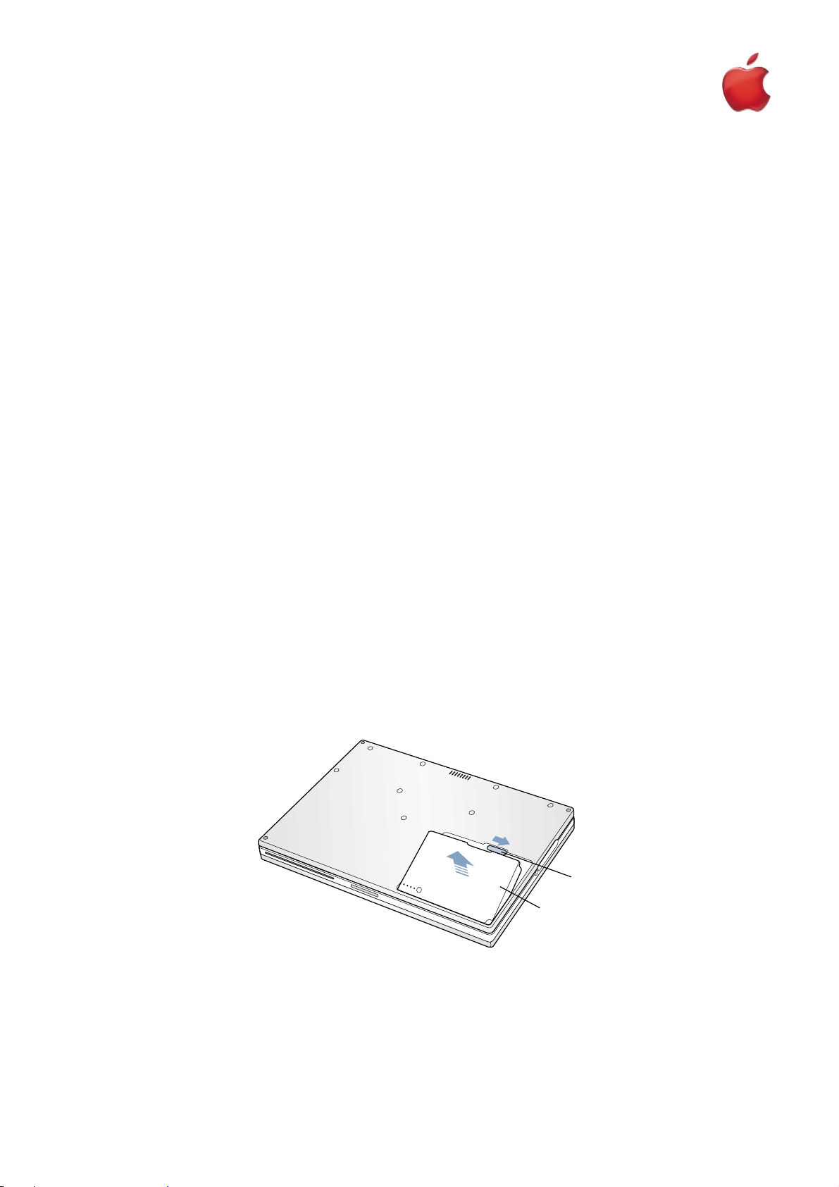
4. Close the computer and turn it over.
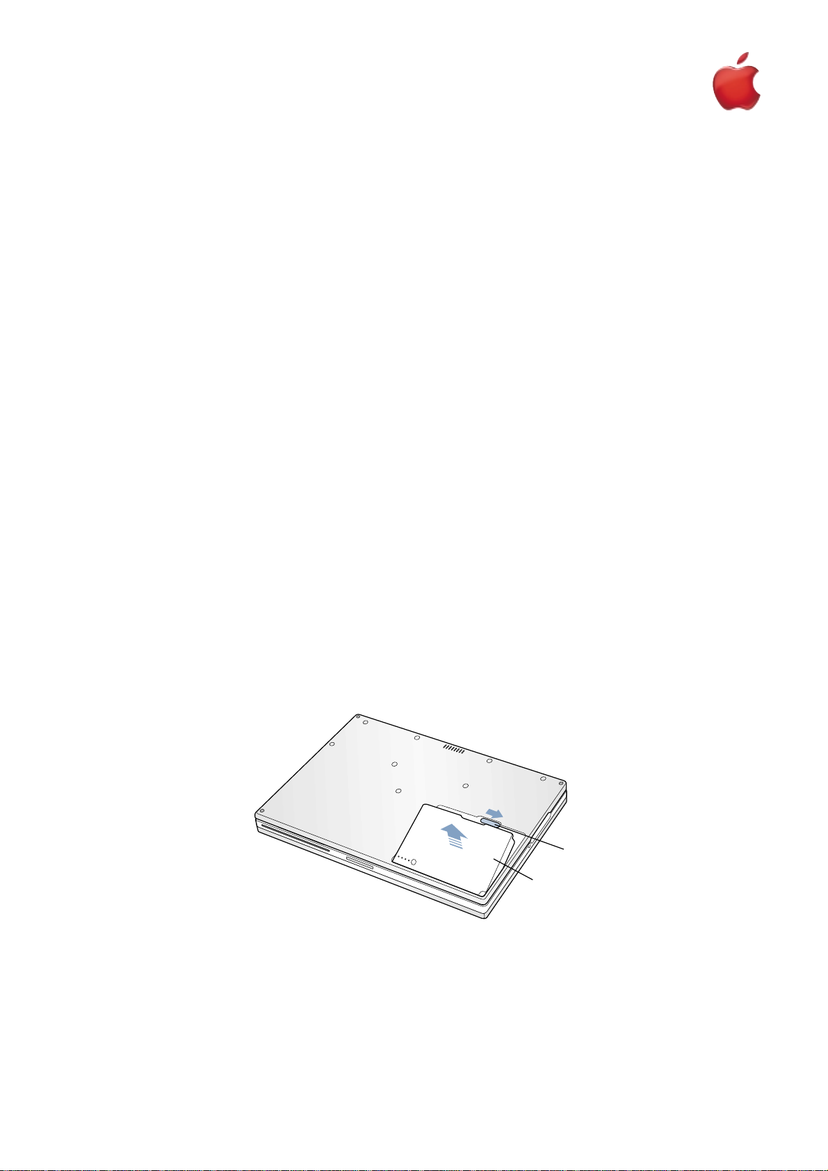
5. Slide the battery latch (Figure 1A) to the right to remove the batter y (Figure 1B).
Removing the battery will prevent you from accidentally tur ning on the computer.
War ning : Removing the battery before shutting down your computer may result in data loss.
6. Turn over the computer.
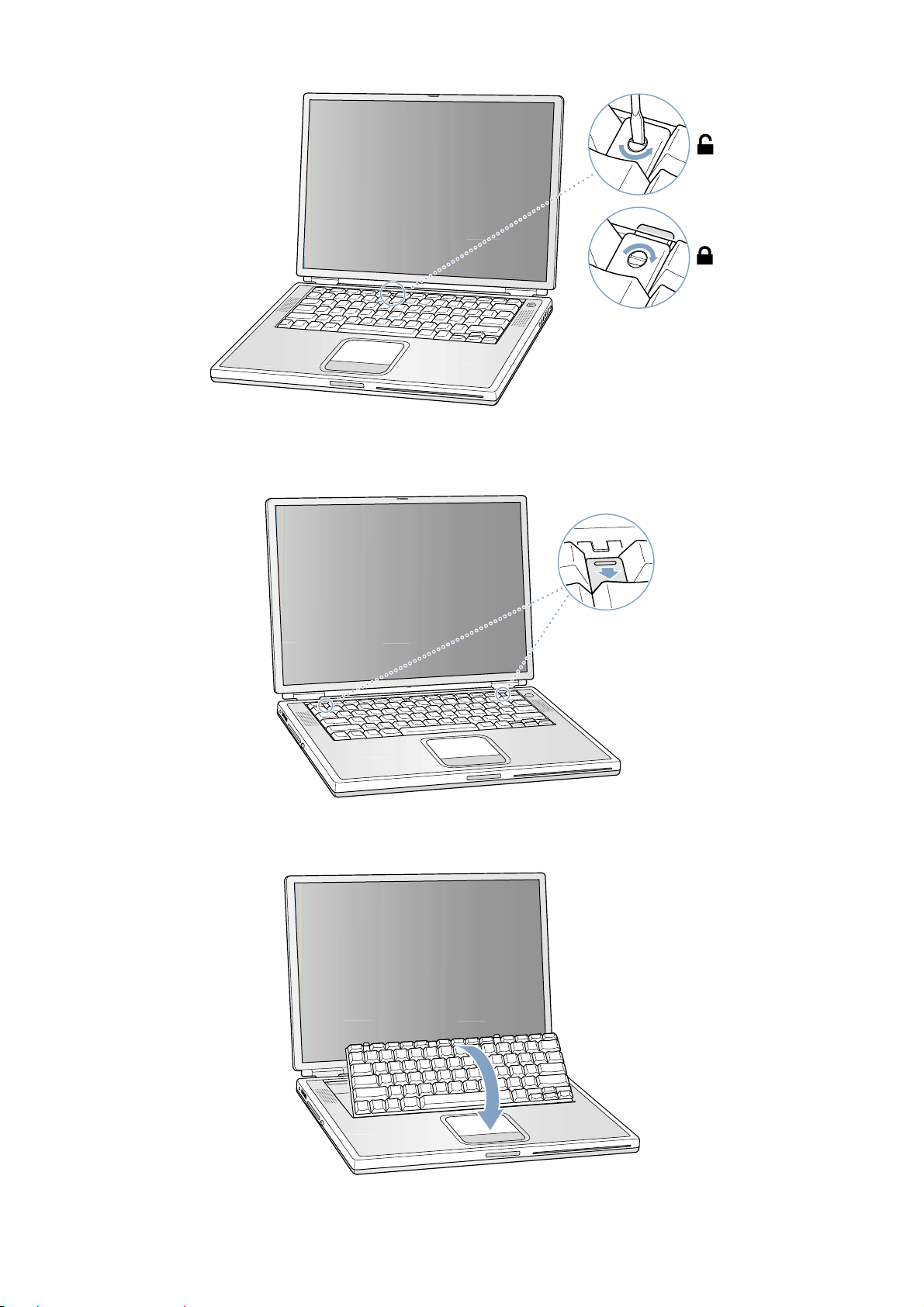
7. Raise the display so you can access the keyboard.
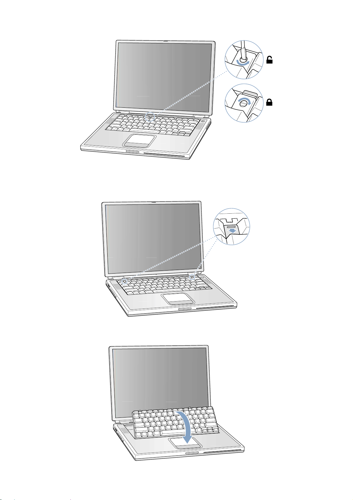
8. Make sure the keyboard locking screw, located in the small plastic tab to the left of the Num L ock key (Figure 2), is not in
the locked position. Your PowerBook comes with the keyboard unlocked, so unless you or someone else locked the keyboard, you can skip this step.
1B073-0635 Rev. A PowerBook G4 (Gigabit Ethernet) - Keyboard
English
English
Keyboard
AppleCare
Figure 1
A
B
Page 13
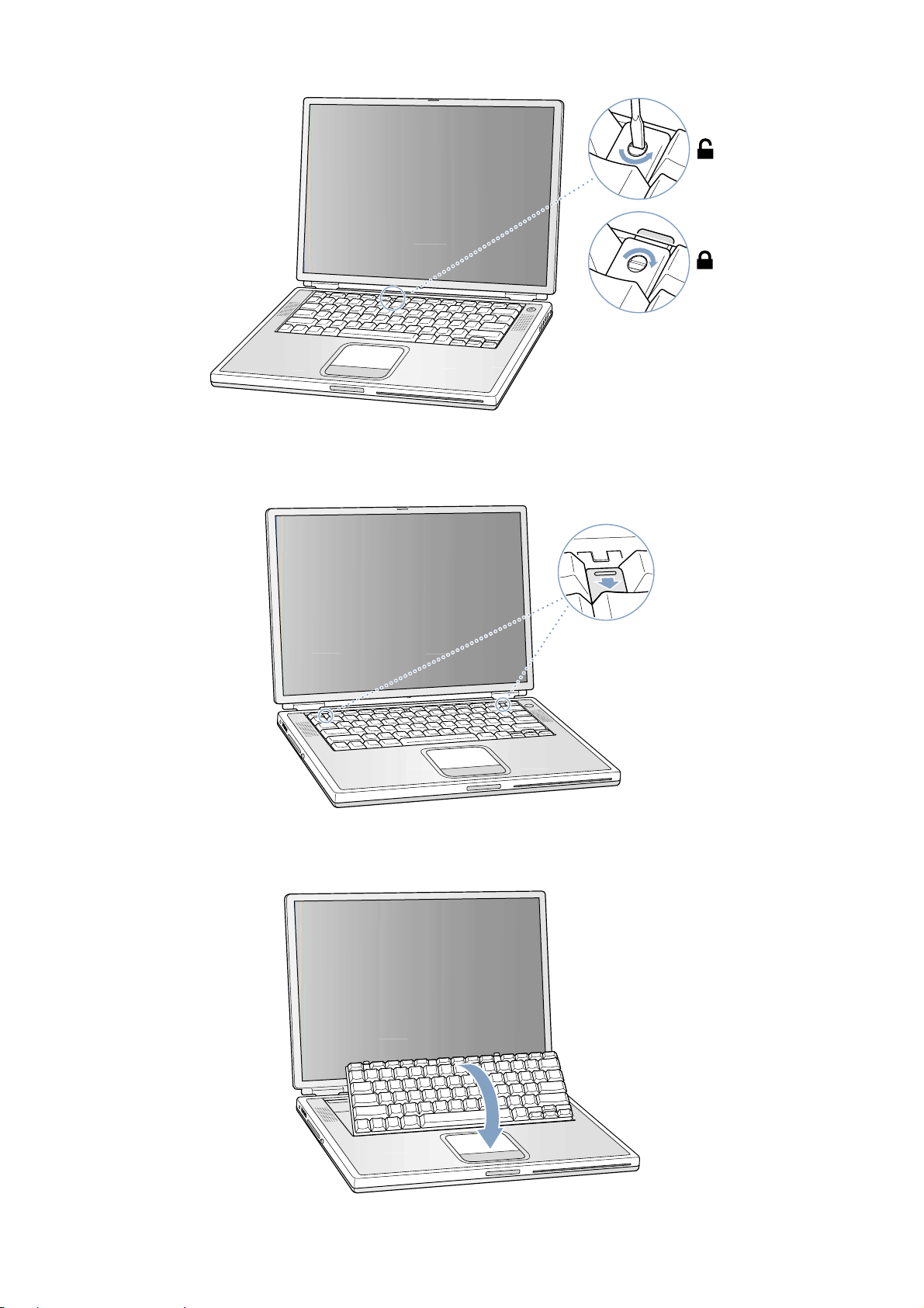
To unlock the keyboard, turn the screw 1/2 turn.
9. Release the keyboard by pulling down on the keyboard release tabs (located to the left of the F1 and F12 keys) (Figure 3),
then lift the top portion of the keyboard up slightly, and toward the display.
10. Flip the keyboard over and lay it on the palm rests and trackpad (Figure 4).
2 B073-0635 Rev. APowerBook G4 (Gigabit Ethernet) - Keyboard
Figure 2
Figure 3
Figure 4
®
Page 14
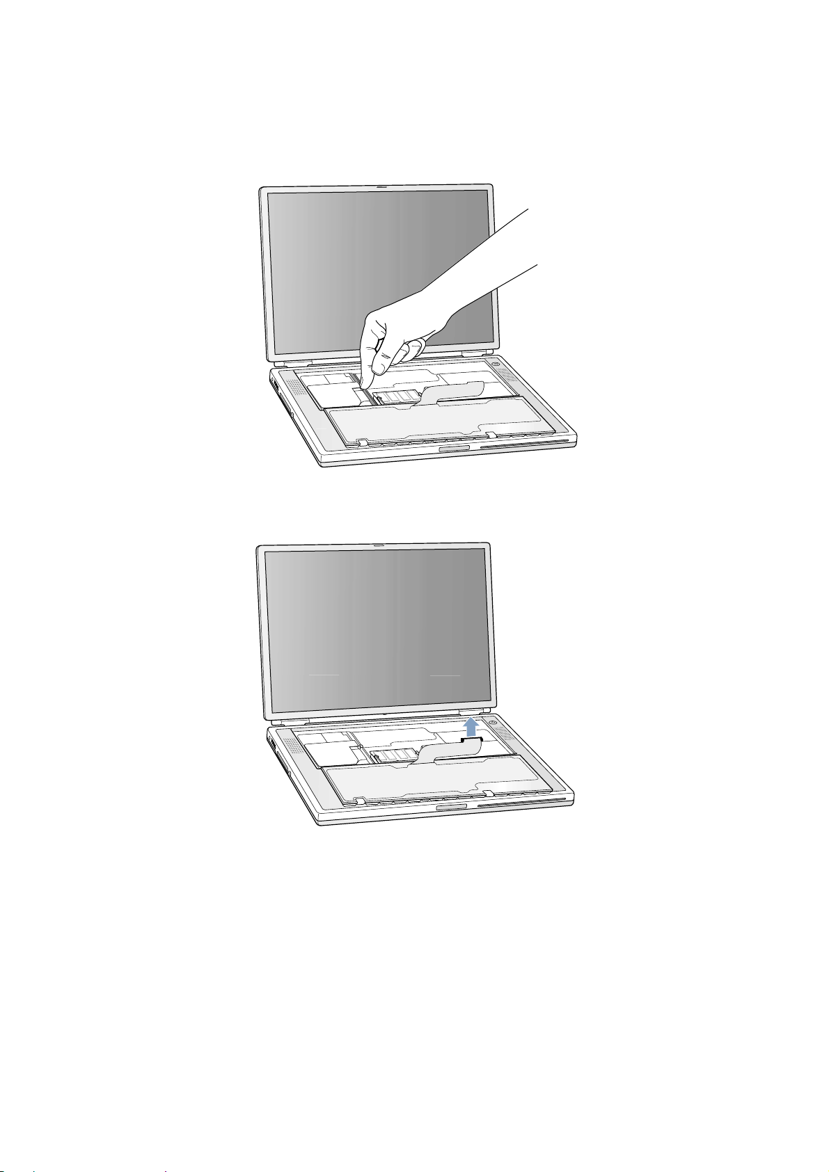
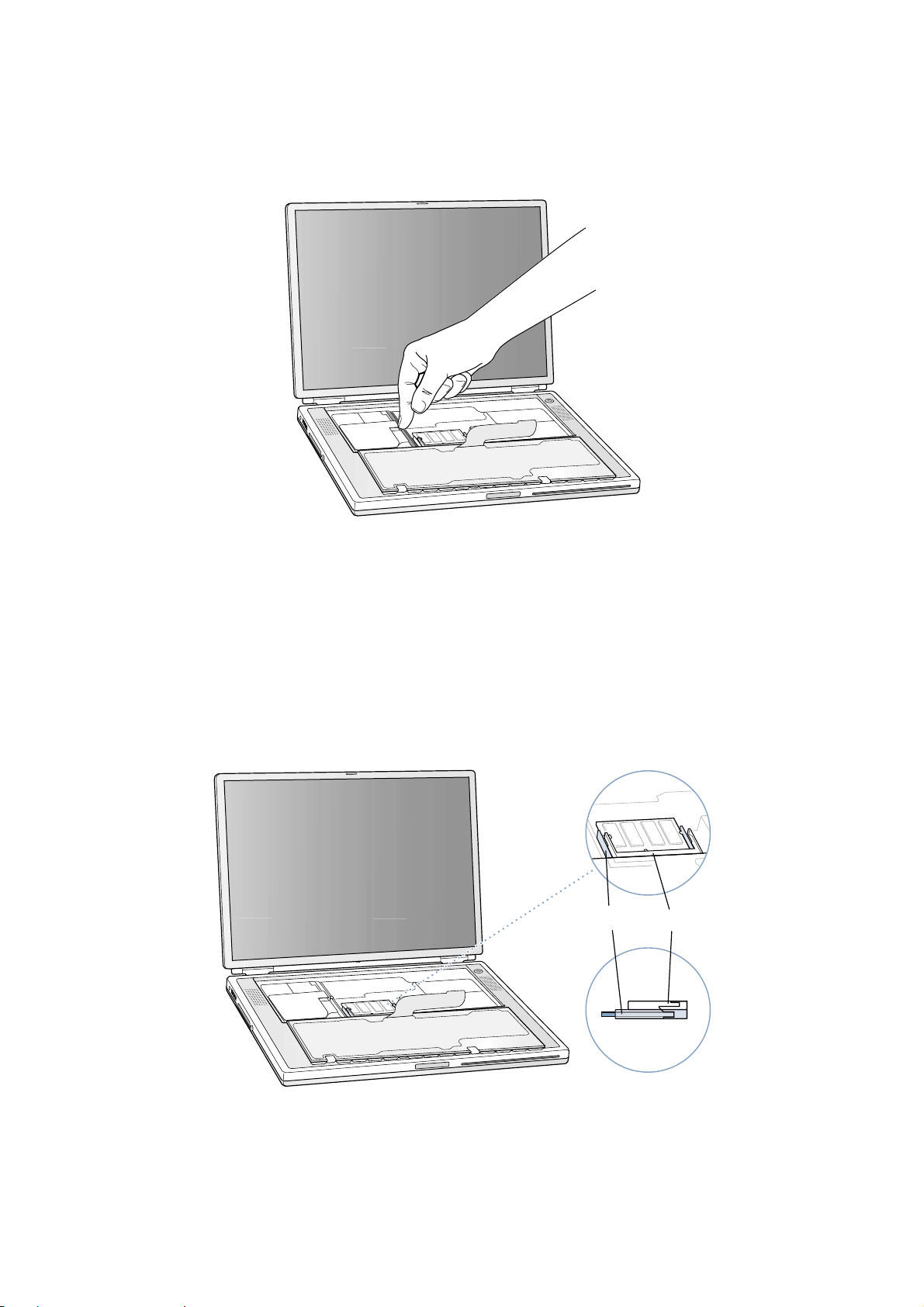
11. Touch the computer’s inside framework (a dull gray conductive composite material) to discharge any static electricity, as
shown (Figure 5).
Important : To avoid electrostatic discharge damage, always ground yourself by touching the computer’s framework before
you touch any parts or install any components inside the computer. To avoid static electricity building back up in your body,
do not walk around the room until you have completed your installation and closed the computer.
12. Locate the keyboard cable connector (Figure 6).
13. Pull up on the connector, from side to side if needed, to disconnect it from the computer.
14. Set the keyboard aside.
3B073-0635 Rev. A PowerBook G4 (Gigabit Ethernet) - Keyboard
Figure 5
Figure 6
Page 15
Installing the Replacement Keyboard
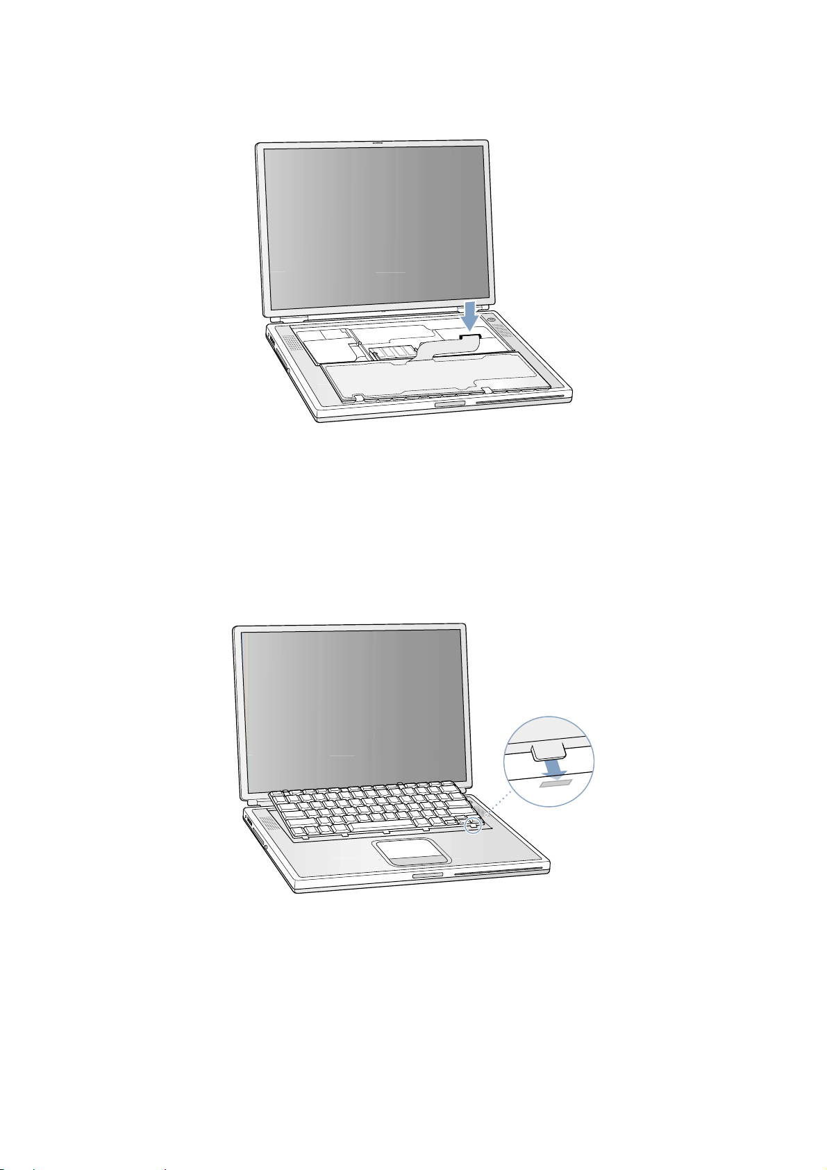
1. Lay the replacement keyboard in the correct orientation over the keyboard opening, then flip it toward you and lay it face
down on the palm rests and trackpad to expose its connector cable (Figure 7).
2. Firmly insert the keyboard cable connector into its connector on the computer.
3. Flip the keyboard back toward the keyboard opening in the case.
4. Hold the keyboard at an angle above the keyboard opening, and insert the tabs on the bottom edge of the keyboard into the
slots below the edge of the opening (Figure 8).
Important : Make sure that all the tabs are seated and that the keyboard rests flush against the edge of the opening.
5. Lay the keyboard flat into the keyboard opening.
4 B073-0635 Rev. APowerBook G4 (Gigabit Ethernet) - Keyboard
Figure 7
Figure 8
Page 16
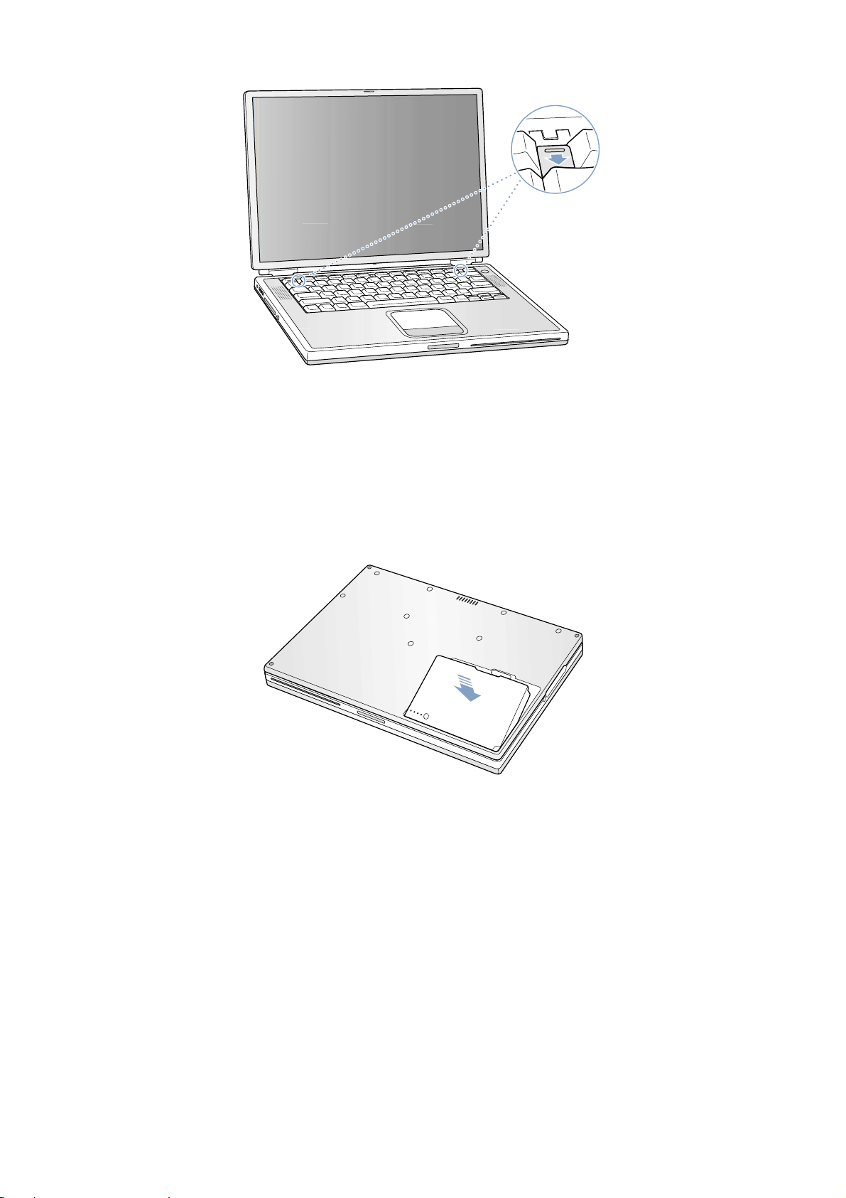
6. Pull down on the keyboard release tabs and then press down on the top portion of the keyboard (Figure 9).
7. Release the tabs to secure the keyboard in place.
8. Close the display and turn the PowerBook over.
9. Replace the battery into the batter y compartment (Figure 10).
Important : Make sure that the battery locks securely into place and that the batter y latch is slid all the way into the locked
position.
10. Reconnect the power cord and any other cables that were connected, and restart your computer.
War ning : Never turn on your computer unless all of its inter nal and exter nal parts are in place and it is
closed. Operating the computer when it is open or missing parts can damage your computer or cause injury.
5B073-0635 Rev. A PowerBook G4 (Gigabit Ethernet) - Keyboard
Figure 9
Figure 10
®
Page 17

Apple Computer, Inc.
© 2001 Apple Computer, Inc. All rights reserved.
Under the copyright laws, this document may not be copied, in whole or in part, without the written consent of Apple.
The Apple logo is a trademark of Apple Computer, Inc., registered in the U.S. and other countries. Use of the “keyboard” Apple logo (Option-Shift-K) for commercial pur-
poses without the prior written consent of Apple may constitute trademark infringement and unfair competition in violation of federal and state laws.
Every effort has been made to ensure that the information in this document is accurate. Apple is not responsible for printing or clerical er rors.
Apple Computer, Inc.
1 Infinite Loop
Cupertino, CA 95014-2084
USA
+ 1 408 996 1010
http://www.apple.com
Apple, the Apple logo, and PowerBook are trademarks of Apple Computer, Inc., registered in the U.S. and other countries.
6 B073-0635 Rev. APowerBook G4 (Gigabit Ethernet) - Keyboard
Page 18

Replacement Instructions
Follow the instructions in this sheet carefully. Failure to follow these instr uctions could damage your equipment and void its
warranty.
Note : Written and video instructions covering customer-installable parts are available at http://www.info.apple.com/installparts/.
War ning : During this procedure, keep small parts away from children.
Tools Required
The only tool required for this procedure is a jeweler’s flat-blade screwdriver (if keyboard is locked).
Opening the Computer
War ning : Always shut down your computer before opening it to avoid damaging its internal components or
causing injury. After you shut down the computer, the internal components can be ver y hot. L et the computer
cool down before continuing.
1. Place your computer on a clean, flat surface.
2. Shut down your computer and wait thirty minutes before continuing.
3. Disconnect the power cord and any other cables connected to the computer.
4. Close the computer and turn it over.
5. Slide the battery latch (Figure 1A) to the right to remove the batter y (Figure 1B).
Removing the battery will prevent you from accidentally tur ning on the computer.
War ning : Removing the battery before shutting down your computer may result in data loss.
6. Turn over the computer.
7. Raise the display so you can access the keyboard.
8. Make sure the keyboard locking screw, located in the small plastic tab to the left of the Num L ock key (Figure 2), is not in
the locked position. Your PowerBook comes with the keyboard unlocked, so unless you or someone else locked the keyboard, you can skip this step.
1PowerBook G4 (Gigabit Ethernet) - Memory
English
English
Memory
AppleCare
Figure 1
A
B
Page 19
To unlock the keyboard, turn the screw 1/2 turn.
9. Release the keyboard by pulling down on the keyboard release tabs (located to the left of the F1 and F12 keys) (Figure 3),
then lift the top portion of the keyboard up slightly, and toward the display.
10. Flip the keyboard over and lay it on the palm rests and trackpad (Figure 4).
2 PowerBook G4 (Gigabit Ethernet) - Memory
Figure 2
Figure 3
Figure 4
®
Page 20
11. Touch the computer’s inside framework (a dull gray conductive composite material) to discharge any static electricity, as
shown (Figure 5).
Important : To avoid electrostatic discharge damage, always ground yourself by touching the computer’s framework before
you touch any parts or install any components inside the computer. To avoid static electricity building back up in your body,
do not walk around the room until you have completed your installation and closed the computer.
Removing the Installed Memory Card
1. To remove a memory card, locate the brackets that secure the card on both sides (Figure 6). Carefully spread the brackets
apart until the card releases on each side. Pull the card up and out.
Note : If there is a memor y card in the upper memory slot (Figure 6A), it must be removed before removing a card in the
lower slot (Figure 6B).
3PowerBook G4 (Gigabit Ethernet) - Memory
Figure 5
Figure 6
B
A
Page 21
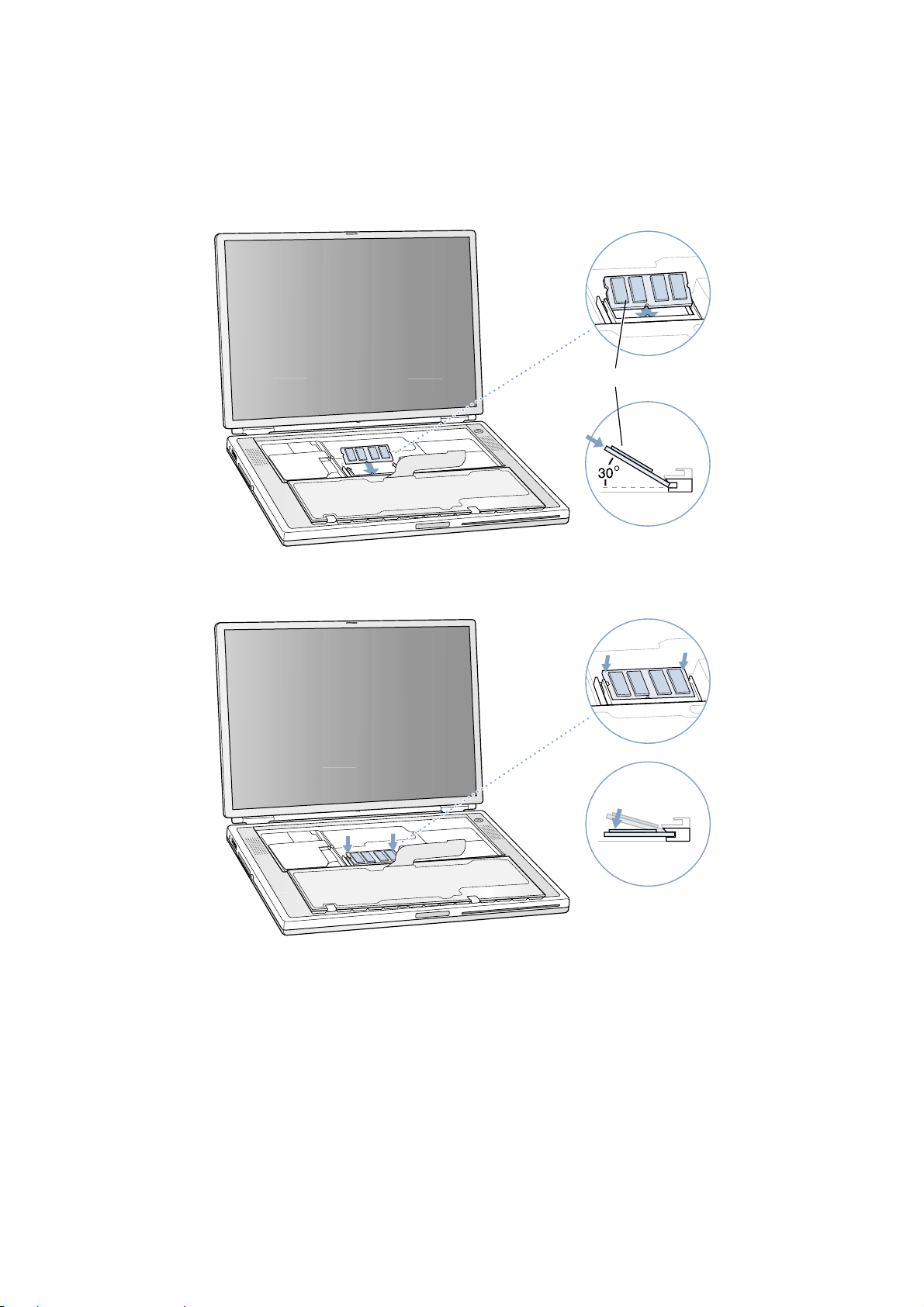
Installing the Replacement Memory Card
War ning : When handling a memory card, do not touch its gold connectors. Handle the card only by the edges.
1. To install the memory card, line up the notch in the card with the small tab in the memor y slot. Hold the card at a 30-degree
angle (Figure 7A), and then push the card into the slot until it is firmly seated.
Note : You may feel some resistance. If you are having trouble inserting the card, try pushing one side at a time.
2. Gently push the card down until the two brackets on either side of the card lock into place (Figure 8).
4 PowerBook G4 (Gigabit Ethernet) - Memory
Figure 7
Figure 8
A
Page 22

Closing the Computer
1. Flip the keyboard back toward the keyboard opening in the case.
2. Hold the keyboard at an angle above the keyboard opening, and insert the tabs on the bottom edge of the keyboard into the
slots below the edge of the opening (Figure 9).
Important : Make sure that all the tabs are seated and that the keyboard rests flush against the edge of the opening.
3. Lay the keyboard flat into the keyboard opening.
4. Pull down on the keyboard release tabs and then press down on the top portion of the keyboard (Figure 10).
5. Release the tabs to secure the keyboard in place.
6. Close the display and turn the PowerBook over.
5PowerBook G4 (Gigabit Ethernet) - Memory
Figure 9
Figure 10
®
Page 23

7. Replace the battery into the batter y compartment (Figure 11).
Important : Make sure that the battery locks securely into place and that the batter y latch is slid all the way into the locked
position.
8. Reconnect the power cord and any other cables that were connected, and restart your computer.
War ning : Never turn on your computer unless all of its inter nal and exter nal parts are in place and it is
closed. Operating the computer when it is open or missing parts can damage your computer or cause injury.
Apple Computer, Inc.
© 2001 Apple Computer, Inc. All rights reserved.
Under the copyright laws, this document may not be copied, in whole or in part, without the written consent of Apple.
The Apple logo is a trademark of Apple Computer, Inc., registered in the U.S. and other countries. Use of the “keyboard” Apple logo (Option-Shift-K) for commercial pur-
poses without the prior written consent of Apple may constitute trademark infringement and unfair competition in violation of federal and state laws.
Every effort has been made to ensure that the information in this document is accurate. Apple is not responsible for printing or clerical er rors.
Apple Computer, Inc.
1 Infinite Loop
Cupertino, CA 95014-2084
USA
+ 1 408 996 1010
http://www.apple.com
Apple, the Apple logo, and PowerBook are trademarks of Apple Computer, Inc., registered in the U.S. and other countries.
6 PowerBook G4 (Gigabit Ethernet) - Memory
Figure 11
Page 24
Replacement Instructions
Follow the instructions in this sheet carefully. Failure to follow these instr uctions could damage your equipment and void its
warranty.
Note : Written and video instructions covering customer-installable parts are available at http://www.info.apple.com/installparts/.
War ning : During this procedure, keep small parts away from children.
Tools Required
• Jeweler’s flat-blade screwdriver (if keyboard is locked)
• 5 mm wrench, 5 mm socket wrench, or needle nose pliers
Opening the Computer
War ning : Always shut down your computer before opening it to avoid damaging its internal components or
causing injury. After you shut down the computer, the internal components can be ver y hot. L et the computer
cool down before continuing.
1. Place your computer on a clean, flat surface.
2. Shut down your computer and wait thirty minutes before continuing.
3. Disconnect the power cord and any other cables connected to the computer.
4. Close the computer and turn it over.
5. Slide the battery latch (Figure 1A) to the right to remove the batter y (Figure 1B).
Removing the battery will prevent you from accidentally tur ning on the computer.
War ning : Removing the battery before shutting down your computer may result in data loss.
6. Turn over the computer.
7. Raise the display so you can access the keyboard.
8. Make sure the keyboard locking screw, located in the small plastic tab to the left of the Num L ock key (Figure 2), is not in
the locked position. Your PowerBook comes with the keyboard unlocked, so unless you or someone else locked the keyboard, you can skip this step.
1B073-0634 Rev. A PowerBook G4 (Gigabit Ethernet) - Modem
English
English
Modem
AppleCare
Figure 1
A
B
Page 25
To unlock the keyboard, turn the screw 1/2 turn.
9. Release the keyboard by pulling down on the keyboard release tabs (located to the left of the F1 and F12 keys) (Figure 3),
then lift the top portion of the keyboard up slightly, and toward the display.
10. Flip the keyboard over and lay it on the palm rests and trackpad (Figure 4).
2 B073-0634 Rev. APowerBook G4 (Gigabit Ethernet) - Modem
Figure 2
Figure 3
Figure 4
®
Page 26
11. Touch the computer’s inside framework (a dull gray conductive composite material) to discharge any static electricity, as
shown (Figure 5).
Important : To avoid electrostatic discharge damage, always ground yourself by touching the computer’s framework before
you touch any parts or install any components inside the computer. To avoid static electricity building back up in your body,
do not walk around the room until you have completed your installation and closed the computer.
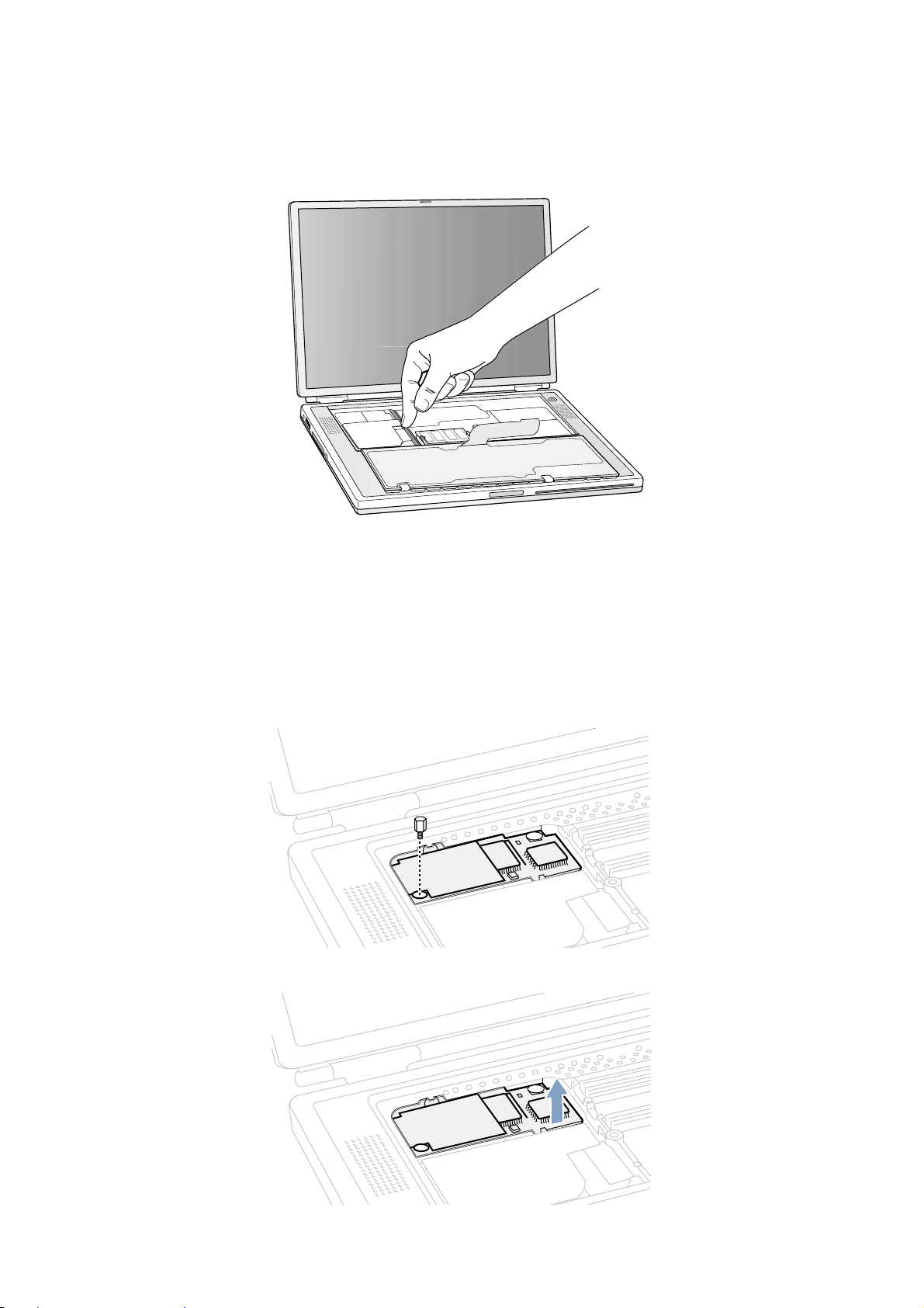
Removing the Installed Modem
War ning : You must remove and install the modem carefully to avoid damaging delicate parts, including the
modem connector and connector cable.
1. Locate the modem and remove the 5 mm hexnut screw (Figure 6).
2. Pull up on the right, front corner of the modem to disconnect it from the logic board (Figure 7).
3B073-0634 Rev. A PowerBook G4 (Gigabit Ethernet) - Modem
Figure 5
Figure 6
Figure 7
Page 27
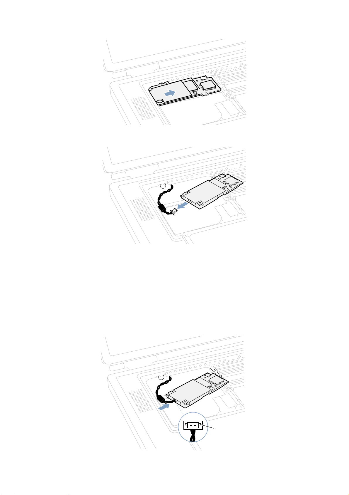
3. Pull the modem up and to the right slightly to reveal the modem connector cable attached to the left end of the modem
(Figure 8).
4. Carefully disconnect the modem cable connector (Figure 9) and remove the modem from the computer.
Installing the Replacement Modem
1. Connect the modem cable connector to the modem (Figure 10).
Note : The connector plugs into the socket located on the top of the modem’s circuit board. The connector and socket are
keyed to fit with the keys up (Figure 10A) .
4 B073-0634 Rev. APowerBook G4 (Gigabit Ethernet) - Modem
Figure 8
Figure 9
Figure 10
A
Page 28
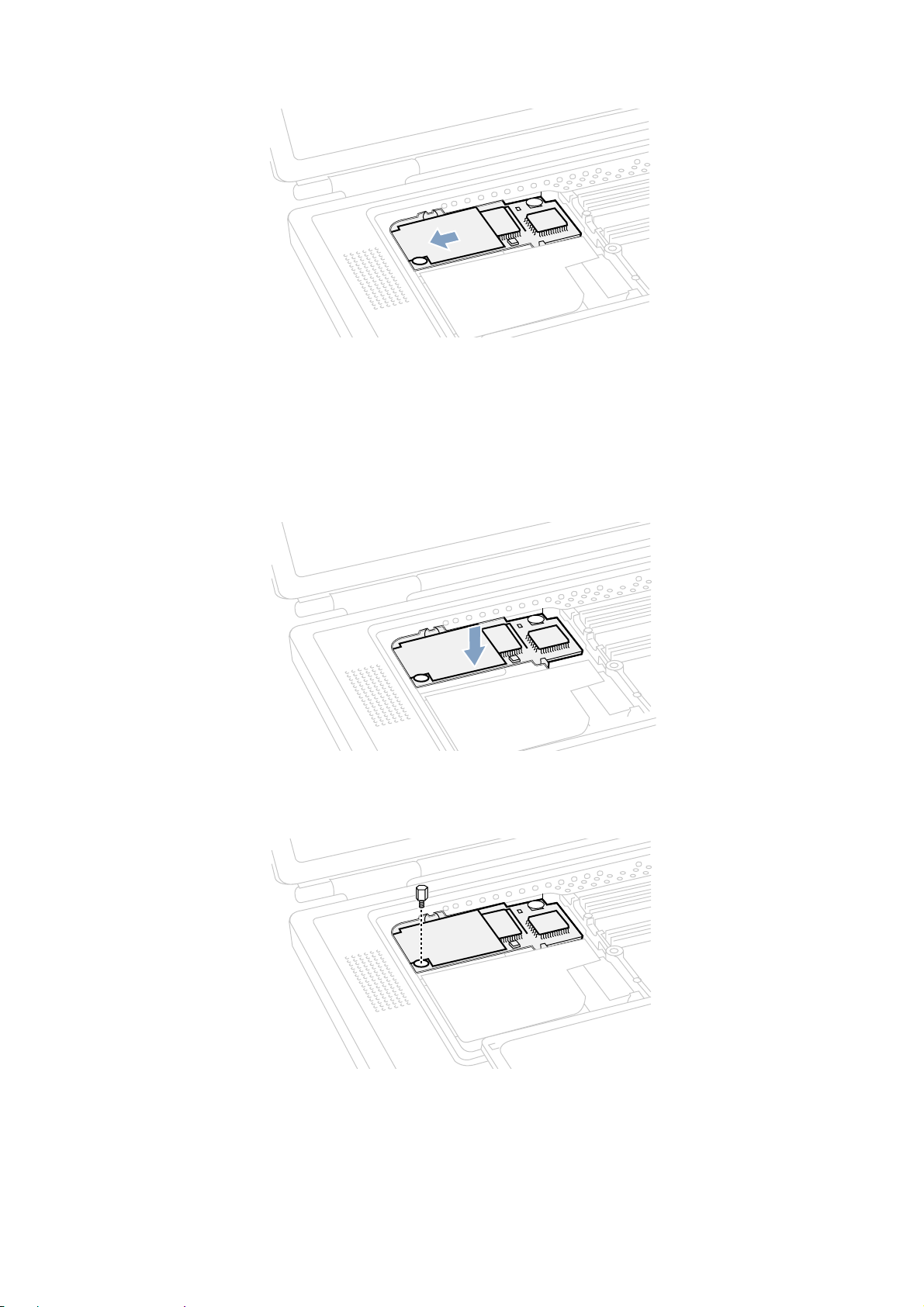
2. Carefully guide the cable into the space under the edge of the keyboard opening and lay the modem into the modem opening (Figure 11).
3. Line up the hexnut screw hole, in the left front corner of the modem, with the hole in the logic board. The modem should
lie flat.
Note : Visually verify that the modem connector cable is still attached.
4. Press down on the front edge of the modem, slightly left of center, to firmly connect it to the logic board (Figure 12).
Note : You may need to maneuver the modem around slightly until you feel the connectors match up.
5. Install the hexnut screw (Figure 13).
Note : It may be helpful to use a finger tip to hold the top of the screw straight and steady while turning the screw.
5B073-0634 Rev. A PowerBook G4 (Gigabit Ethernet) - Modem
Figure 12
Figure 13
Figure 11
Page 29
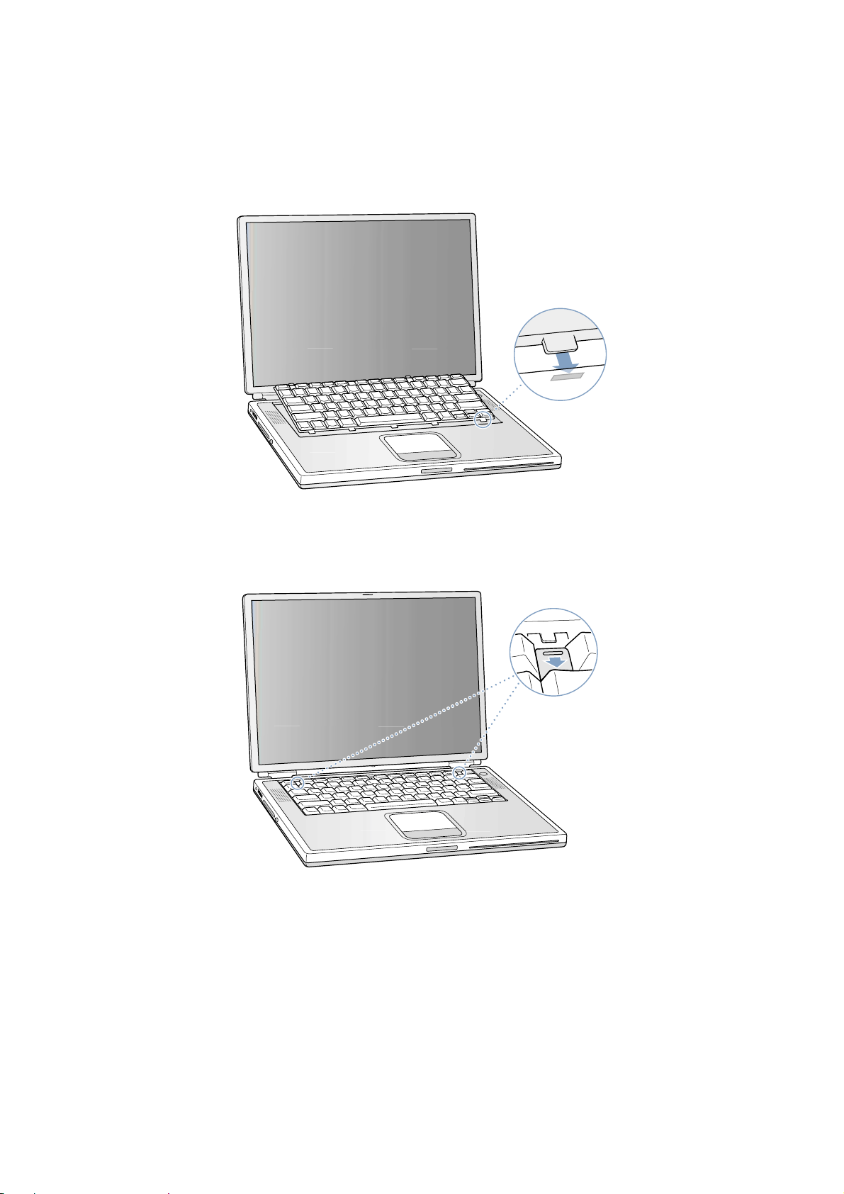
Closing the Computer
1. Flip the keyboard back toward the keyboard opening in the case.
2. Hold the keyboard at an angle above the keyboard opening, and insert the tabs on the bottom edge of the keyboard into the
slots below the edge of the opening (Figure 14).
Important : Make sure that all the tabs are seated and that the keyboard rests flush against the edge of the opening.
3. Lay the keyboard flat into the keyboard opening.
4. Pull down on the keyboard release tabs and then press down on the top portion of the keyboard (Figure 15).
5. Release the tabs to secure the keyboard in place.
6. Close the display and turn the PowerBook over.
6 B073-0634 Rev. APowerBook G4 (Gigabit Ethernet) - Modem
Figure 15
Figure 14
®
Page 30

7. Replace the battery into the batter y compartment (Figure 16).
Important : Make sure that the battery locks securely into place and that the batter y latch is slid all the way into the locked
position.
8. Reconnect the power cord and any other cables that were connected, and restart your computer.
War ning : Never turn on your computer unless all of its inter nal and exter nal parts are in place and it is
closed. Operating the computer when it is open or missing parts can damage your computer or cause injury.
Replacing International Modems
After you have replaced a modem in Europe or Asia, open the software utility Modem Countr y Selector and verif y that the
modem is set to the correct countr y. Modem Country Selector is located in the Apple Extras folder on your hard drive or can
be downloaded as part of the Apple Modem Updater software bundle at http://asu.info.apple.com.
Apple Computer, Inc.
© 2001 Apple Computer, Inc. All rights reserved.
Under the copyright laws, this document may not be copied, in whole or in part, without the written consent of Apple.
The Apple logo is a trademark of Apple Computer, Inc., registered in the U.S. and other countries. Use of the “keyboard” Apple logo (Option-Shift-K) for commercial pur-
poses without the prior written consent of Apple may constitute trademark infringement and unfair competition in violation of federal and state laws.
Every effort has been made to ensure that the information in this document is accurate. Apple is not responsible for printing or clerical er rors.
Apple Computer, Inc.
1 Infinite Loop
Cupertino, CA 95014-2084
USA
+ 1 408 996 1010
http://www.apple.com
Apple, the Apple logo, and PowerBook are trademarks of Apple Computer, Inc., registered in the U.S. and other countries.
7B073-0634 Rev. A PowerBook G4 (Gigabit Ethernet) - Modem
Figure 16
Page 31

Replacement Instructions
Follow the instructions in this sheet carefully. Failure to follow these instr uctions could damage your equipment and void its
warranty.
Note : Written and video instructions covering customer-installable parts are available at http://www.info.apple.com/installparts/.
War ning : Sharp edges can exist inside your computer and on any parts being removed or installed. Use caution
to avoid injury. Keep small parts away from children.
Tools Required
• Soft towel or cloth, larger than the PowerBook
• Torx T8 screwdriver
Removing the Bottom Case
War ning : Always shut down your computer before opening it to avoid damaging its internal components or
causing injury. After you shut down the computer, the internal components can be ver y hot. L et the computer
cool down before continuing.
1. Place your computer on a clean, flat surface.
2. Shut down your computer and wait thirty minutes before continuing.
3. Disconnect the power cord and any other cables connected to the computer.
4. Place a towel or soft cloth on a table in front of you (Figure 1A).
The towel or cloth will protect the keyboard and display area of the PowerBook when you flip it over to remove the battery
and bottom case. Make sure it covers an area large enough for your PowerBook and that it hangs over the edge of the table.
5. With the display open at an angle greater than 90 degrees, carefully flip the PowerBook over and lay it flat, fully on the table.
Make sure the display hangs over the edge of the table and rests lightly on your lap (Figure 1B).
Important : Do not open the display farther than the angle shown.
1B073-0600 Rev. D PowerBook G4 (Gigabit Ethernet) - Bottom Case
English
English
Bottom Case
AppleCare
Figure 1
A
B
Page 32

6. Remove the battery by sliding the batter y latch to the lef t. Make sure to return the latch fully to the right (Figure 2).
Removing the battery will prevent you from accidentally tur ning on the computer.
War ning : Removing the battery before shutting down your computer may result in data loss.
7. Using a Torx T8 screwdriver, remove the eight bottom case screws in the order shown in the illustration (Figure 3).
Important : To avoid damaging the case, be careful that the screwdriver tip does not slip out of the screw head during
removal.
Note : The following three steps explain how to remove the bottom case by disengaging it at the left and right sides and
then carefully pivoting it forward.
Important : During this procedure, do not push on the rubber feet of the bottom case.
2 B073-0600 Rev. DPowerBook G4 (Gigabit Ethernet) - Bottom Case
Figure 2
Figure 3
1
3
2
8
7
6
4
5
Page 33

8. Place your hands on the bottom case as shown (Figure 4) and push away from you until the left side releases.
9. Place your hands on the bottom case as shown (Figure 5) and push away from you until the right side releases.
10. When both sides have released, lift up on the edge of the bottom case that is closest to you ; carefully and evenly pivot it
over the front edge of the computer until it releases (Figure 6).
Important : Do not twist the bottom case from side to side. Slide the case forward completely before lifting it up. If you
feel any resistance when lifting the bottom case, double-check to make sure the case is slid all the way forward and releases
from the front edge.
3B073-0600 Rev. D PowerBook G4 (Gigabit Ethernet) - Bottom Case
Figure 6
Figure 4
Figure 5
Page 34

Installing the Replacement Bottom Case
1. To install the new bottom case, place it over the bottom of the computer in the same orientation as the original bottom case.
2. Align the notches on the right and left sides of the case (some of these can be viewed through the batter y opening). Then
press down and toward you slightly to secure the case.
Important : Make sure that the seams between the bottom case and the frame are closed. Verify that the case lies flat and
fits properly around the battery latch and that the alignment tab that protr udes on the underside of the bottom case, shown
in the illustration (Figure 7A), is seated properly.
Note : To help with alignment, apply pressure to the bottom case at the back of the battery compartment opening, near the
latch, and on the front and back outside edges of the case.
3. Check that the eight screw holes on the case align with the holes on the computer.
4. Replace the eight screws in the order shown in the illustration (Figure 7). Do not overtighten the screws or damage could
result.
Note : The screws must go in straight and easily ; if they do not, readjust the bottom case for proper alignment.
Important : To avoid damaging the case, be careful that the screwdriver tip does not slip out of the screw head during
tightening.
5. Replace the battery (Figure 8).
Important : Make sure that the battery locks securely into place and that the batter y latch is slid all the way into the locked
position.
4 B073-0600 Rev. DPowerBook G4 (Gigabit Ethernet) - Bottom Case
Figure 7
Figure 8
8
A
7
1
3
6
2
5
4
Page 35

6. Turn the computer over so that the optical drive slot faces you. Verify that the bottom case is flush with the front edge of the
slot. If the case is slightly bowed and there is a gap near the center of the slot, carefully pull the bottom edge of the slot until
it clicks into place and becomes flush with the bottom case (Figure 9).
7. Reconnect the power cord and any other cables that were connected, and restart your computer.
War ning : Never turn on your computer unless all of its inter nal and exter nal parts are in place and it is
closed. Operating the computer when it is open or missing parts can damage your computer or cause injury.
Apple Computer, Inc.
© 2001 Apple Computer, Inc. All rights reserved.
Under the copyright laws, this document may not be copied, in whole or in part, without the written consent of Apple.
The Apple logo is a trademark of Apple Computer, Inc., registered in the U.S. and other countries. Use of the “keyboard” Apple logo (Option-Shift-K) for commercial pur-
poses without the prior written consent of Apple may constitute trademark infringement and unfair competition in violation of federal and state laws.
Every effort has been made to ensure that the information in this document is accurate. Apple is not responsible for printing or clerical er rors.
Apple Computer, Inc.
1 Infinite Loop
Cupertino, CA 95014-2084
USA
+ 1 408 996 1010
http://www.apple.com
Apple, the Apple logo, and PowerBook are trademarks of Apple Computer, Inc., registered in the U.S. and other countries.
5B073-0600 Rev. D PowerBook G4 (Gigabit Ethernet) - Bottom Case
Figure 9
®
Page 36

Replacement Instructions
Follow the instructions in this sheet carefully. Failure to follow these instr uctions could damage your equipment and void its
warranty.
Note : Written and video instructions covering customer-installable parts are available at http://www.info.apple.com/installparts/.
War ning : Sharp edges can exist inside your computer and on any parts being removed or installed. Use caution
to avoid injury. Keep small parts away from children.
Tools Required
• Soft towel or cloth, larger than the PowerBook
• Torx T8 screwdriver
Opening the Computer
War ning : Always shut down your computer before opening it to avoid damaging its internal components or
causing injury. After you shut down the computer, the internal components can be ver y hot. L et the computer
cool down before continuing.
To access the AirPort Card, you must first remove the battery and bottom case.
1. Place your computer on a clean, flat surface.
2. Shut down your computer and wait thirty minutes before continuing.
3. Disconnect the power cord and any other cables connected to the computer.
4. Place a towel or soft cloth on a table in front of you (Figure 1A).
The towel or cloth will protect the keyboard and display area of the PowerBook when you flip it over to remove the battery
and bottom case. Make sure it covers an area large enough for your PowerBook and that it hangs over the edge of the table.
5. With the display open at an angle greater than 90 degrees, carefully flip the PowerBook over and lay it flat, fully on the table.
Make sure the display hangs over the edge of the table and rests lightly on your lap (Figure 1B).
Important : Do not open the display farther than the angle shown.
1PowerBook G4 (Gigabit Ethernet) - AirPort Card
English
English
AirPort Card
AppleCare
Figure 1
A
B
Page 37

6. Remove the battery by sliding the batter y latch to the lef t. Make sure to return the latch fully to the right (Figure 2).
Removing the battery will prevent you from accidentally tur ning on the computer.
War ning : Removing the battery before shutting down your computer may result in data loss.
7. Using a Torx T8 screwdriver, remove the eight bottom case screws in the order shown in the illustration (Figure 3).
Important : To avoid damaging the case, be careful that the screwdriver tip does not slip out of the screw head during
removal.
Note : The following three steps explain how to remove the bottom case by disengaging it at the left and right sides and
then carefully pivoting it forward.
Important : During this procedure, do not push on the rubber feet of the bottom case.
8. Place your hands on the bottom case as shown (Figure 4) and push away from you until the left side releases.
2 PowerBook G4 (Gigabit Ethernet) - AirPort Card
Figure 2
Figure 3
Figure 4
1
3
2
8
7
6
4
5
Page 38

9. Place your hands on the bottom case as shown (Figure 5) and push away from you until the right side releases.
10. When both sides have released, lift up on the edge of the bottom case that is closest to you; carefully and evenly pivot it
over the front edge of the computer until it releases (Figure 6).
Important : Do not twist the bottom case from side to side. Slide the case forward completely before lifting it up. If you
feel any resistance when lifting the bottom case, double-check to make sure the case is slid all the way forward and releases
from the front edge.
11. Touch the computer’s inside framework (a dull gray conductive composite material) to discharge any static electricity, as
shown (Figure 7).
Important : To avoid electrostatic discharge damage, always ground yourself by touching the computer’s framework before
you touch any parts or install any components inside the computer. To avoid static electricity building back up in your body,
do not walk around the room until you have completed your installation and closed the computer.
3PowerBook G4 (Gigabit Ethernet) - AirPort Card
Figure 5
Figure 6
Figure 7
Page 39

Removing the Installed AirPort Card
1. Pull back on the antenna clip (Figure 8A) to release the antenna cable connector (Figure 8B) and allow the card to rise up
slightly.
2. Pull the card from the AirPort connector (Figure 8D).
3. Hold the AirPort Card with one hand and grasp the antenna cable connector with the other. While being careful not to strain
the antenna cable (Figure 8C), firmly pull the connector straight out of the AirPort Card.
Important : If the AirPort Card is not being replaced right away, replace the antenna cable connector into its holder
(Figure 10B) and pull the loop of the antenna cable up slightly and away from the edge of the computer case. This prevents the cable from interfering with the PC card slot, below, or getting pinched during reassembly.
Also, if the insertion end of the AirPort Card connector is rotated up, push it down into the level position. This allows the
bottom case to install properly.
4 PowerBook G4 (Gigabit Ethernet) - AirPort Card
Figure 8
D
C
A
B
Page 40

Installing the Replacement AirPort Card
1. If the AirPort Card to be installed came with the AirPort adapter (Figure 9A), remove the metal clip (Figure 9B) and pull
the AirPort Card (Figure 9C) from the adapter. (The adapter and metal clip are not used with your PowerBook.)
2. If necessary, pull the AirPort antenna cable connector (Figure 10A) from its holder (Figure 10B).
3. Pull up the insertion end of the AirPort Card connector (Figure 11A) to raise it up slightly, if it is not already up.
4. Position the AirPort Card (Figure 11B) with the AirPort ID numbers and bar code facing up and slide the card into the con-
nector. Make sure to slide the card all the way in until the card is securely attached to the connector.
5PowerBook G4 (Gigabit Ethernet) - AirPort Card
Figure 10
Figure 11
Figure 9
A
C
B
B
A
B
A
Page 41

5. Lug the antenna cable connector (Figure 12A) into the port, which is located just below the plastic tab (Figure 12B), on
the end of the AirPort Card. Make sure the connector is straight before inserting it into the card.
6. Push the AirPort Card down into its space until the antenna cable connector is secured by the small antenna clip (Figure
12C).
Important : Route the antenna cable (Figure 12D) between the edge of the computer and the AirPort Card. Verify that the
cable is away from the edge of the computer so that it will not be pinched during reassembly and that it does not sag down
into the PC card slot area (below the AirPort Card). Take up any extra cable by tucking it in where shown (Figure 12E).
7. Fold the plastic tab (Figure 12B) on the AirPort Card over the top of the card.
Note : The plastic tab must be folded over the card during the installation of the bottom case ; otherwise you will not be
able to securely attach the bottom case to the computer.
6 PowerBook G4 (Gigabit Ethernet) - AirPort Card
Figure 12
E
B
D
C
A
Page 42

Closing the Computer
1. To replace the bottom case, place it over the bottom of the computer in the same orientation as the original bottom case.
2. Align the notches on the right and left sides of the case (some of these can be viewed through the batter y opening). Then
press down and toward you slightly to secure the case.
Important : Make sure that the seams between the bottom case and the frame are closed. Verify that the case lies flat and
fits properly around the battery latch and that the alignment tab that protr udes on the underside of the bottom case, shown
in the illustration (Figure 13A), is seated properly.
Note : To help with alignment, apply pressure to the bottom case at the back of the battery compartment opening, near the
latch, and on the front and back outside edges of the case.
3. Check that the eight screw holes on the case align with the holes on the computer.
4. Replace the eight screws in the order shown in the illustration (Figure 13). Do not overtighten the screws or damage could
result.
Note : The screws must go in straight and easily; if they do not, readjust the bottom case for proper alignment.
Important : To avoid damaging the case, be careful that the screwdriver tip does not slip out of the screw head during
tightening.
5. Replace the battery (Figure 14).
Important : Make sure that the battery locks securely into place and that the batter y latch is slid all the way into the locked
position.
7PowerBook G4 (Gigabit Ethernet) - AirPort Card
Figure 14
Figure 13
8
A
7
1
3
6
2
5
4
Page 43

6. Turn the computer over so that the optical drive slot faces you. Verify that the bottom case is flush with the front edge of the
slot. If the case is slightly bowed and there is a gap near the center of the slot, carefully pull the bottom edge of the slot until
it clicks into place and becomes flush with the bottom case (Figure 15).
7. Reconnect the power cord and any other cables that were connected, and restart your computer.
War ning : Never turn on your computer unless all of its inter nal and exter nal parts are in place and it is
closed. Operating the computer when it is open or missing parts can damage your computer or cause injury.
Apple Computer, Inc.
© 2001 Apple Computer, Inc. All rights reserved.
Under the copyright laws, this document may not be copied, in whole or in part, without the written consent of Apple.
The Apple logo is a trademark of Apple Computer, Inc., registered in the U.S. and other countries. Use of the “keyboard” Apple logo (Option-Shift-K) for commercial pur-
poses without the prior written consent of Apple may constitute trademark infringement and unfair competition in violation of federal and state laws.
Every effort has been made to ensure that the information in this document is accurate. Apple is not responsible for printing or clerical er rors.
Apple Computer, Inc.
1 Infinite Loop
Cupertino, CA 95014-2084
USA
+ 1 408 996 1010
http://www.apple.com
Apple, the Apple logo, and PowerBook are trademarks of Apple Computer, Inc., registered in the U.S. and other countries.
AirPort is a trademark of Apple Computer, Inc.
8 PowerBook G4 (Gigabit Ethernet) - AirPort Card
Figure 15
®
Page 44

Replacement Instructions
Follow the instructions in this sheet carefully. Failure to follow these instr uctions could damage your equipment and void its
warranty.
Note : Written and video instructions covering customer-installable parts are available at http://www.info.apple.com/installparts/.
War ning : Sharp edges can exist inside your computer and on any parts being removed or installed. Use caution
to avoid injury. Keep small parts away from children.
Tools Required
• Soft towel or cloth, larger than the PowerBook
• Torx T8 screwdriver
Backing Up Your Data
War ning : Before replacing your hard drive, make sure you back up all data on the drive.
Opening the Computer
War ning : Always shut down your computer before opening it to avoid damaging its internal components or
causing injury. After you shut down the computer, the internal components can be ver y hot. L et the computer
cool down before continuing.
To access the hard drive, you must first remove the battery and bottom case.
1. Place your computer on a clean, flat surface.
2. Shut down your computer and wait thirty minutes before continuing.
3. Disconnect the power cord and any other cables connected to the computer.
4. Place a towel or soft cloth on a table in front of you (Figure 1A).
The towel or cloth will protect the keyboard and display area of the PowerBook when you flip it over to remove the battery
and bottom case. Make sure it covers an area large enough for your PowerBook and that it hangs over the edge of the table.
5. With the display open at an angle greater than 90 degrees, carefully flip the PowerBook over and lay it flat, fully on the table.
Make sure the display hangs over the edge of the table and rests lightly on your lap (Figure 1B).
Important : Do not open the display farther than the angle shown.
1B073-0633 Rev. A PowerBook G4 (Gigabit Ethernet) - Hard Drive
English
English
Hard Drive
AppleCare
Figure 1
A
B
Page 45

6. Remove the battery by sliding the batter y latch to the lef t. Make sure to return the latch fully to the right (Figure 2).
Removing the battery will prevent you from accidentally tur ning on the computer.
War ning : Removing the battery before shutting down your computer may result in data loss.
7. Using a Torx T8 screwdriver, remove the eight bottom case screws in the order shown in the illustration (Figure 3).
Important : To avoid damaging the case, be careful that the screwdriver tip does not slip out of the screw head during
removal.
Note : The following three steps explain how to remove the bottom case by disengaging it at the left and right sides and
then carefully pivoting it forward.
Important : During this procedure, do not push on the rubber feet of the bottom case.
8. Place your hands on the bottom case as shown (Figure 4) and push away from you until the left side releases.
2 B073-0633 Rev. APowerBook G4 (Gigabit Ethernet) - Hard Drive
Figure 2
Figure 3
Figure 4
1
3
2
8
7
6
4
5
Page 46

9. Place your hands on the bottom case as shown (Figure 5) and push away from you until the right side releases.
10. When both sides have released, lift up on the edge of the bottom case that is closest to you; carefully and evenly pivot it
over the front edge of the computer until it releases (Figure 6).
Important : Do not twist the bottom case from side to side. Slide the case forward completely before lifting it up. If you
feel any resistance when lifting the bottom case, double-check to make sure the case is slid all the way forward and releases
from the front edge.
11. Touch the computer’s inside framework (a dull gray conductive composite material) to discharge any static electricity, as
shown (Figure 7).
Important : To avoid electrostatic discharge damage, always ground yourself by touching the computer’s framework before
you touch any parts or install any components inside the computer. To avoid static electricity building back up in your body,
do not walk around the room until you have completed your installation and closed the computer.
3B073-0633 Rev. A PowerBook G4 (Gigabit Ethernet) - Hard Drive
Figure 5
Figure 6
Figure 7
Page 47

Removing the Installed Hard Drive
1. With your fingers, carefully pry up the hard drive cable connector (Figure 8) at its sides to disconnect it from the logic
board. You may need to pry one side, then the other, in a rocking motion.
2. With a Torx T8 screwdriver, remove the two screws (Figure 9) that secure the hard drive to the mounting bracket and then
gently remove the hard drive.
Important : Do not pull on the connector cable or use the cable as a handle.
Note : There are four rubber stoppers on the hard drive that fit over screws (two on each side). Remove any that may have
fallen off or that remain in the holes in the mounting bracket inside the computer.
3. Replace the screws and rubber stoppers back onto the removed hard drive.
4 B073-0633 Rev. APowerBook G4 (Gigabit Ethernet) - Hard Drive
Figure 8
Figure 9
Page 48

Installing the Replacement Hard Drive
War ning : To avoid potential injury, avoid touching or brushing against the thin strip of metal that extends up
from the hard drive mounting bracket (Figure 10A).
Important : Avoid touching the optical drive as you perform this procedure.
1. With a Torx T8 screwdriver, remove the screw from the top of the hard drive mounting bracket (Figure 10B).
2. Carefully lift the mounting bracket up (Figure 10C) and gently bend it around the first battery bay tab (Figure 10D). The
tab holds the bracket out of the way.
War ning : Lif t the bracket just high enough to clear the batter y bay tab. If you lift the bracket higher than the
tab you risk damaging the bracket, and such damage is not covered by the limited warranty on your computer.
3. Verif y that the replacement hard drive has four screws (Figure 11A), two on each side, with four rubber stoppers (Figure
11B) attached.
Important : If any screws or stoppers have come off, screw the screws back onto the hard drive and then slide the rubber
stoppers over them until they are against the drive. Make sure that the Mylar sheath (Figure 11C) wraps around the bottom and left and right sides of the drive, and that the rubber stoppers protr ude through the holes in the sheath along the
sides.
5B073-0633 Rev. A PowerBook G4 (Gigabit Ethernet) - Hard Drive
Figure 10
Figure 11
B
D
A
C
C
B
A
Page 49

4. Insert the right side of the drive first, until the rubber stoppers fit securely into the holes in the bracket, and then insert the
left side of the drive (Figure 12).
5. Lift the mounting bracket (Figure 13A) over the battery bay tab and lower it to its original position. Line up the rubber
stoppers on the hard drive until they fully seat into the holes in the bracket.
Note : To help with alignment, the Torx T8 screwdriver can be inserted into the screws on the hard drive through the holes
in the mounting bracket.
Important : Verif y that the bottom of the mounting bracket clears and seats behind a thin metal ridge located along the
bottom of the battery compartment (Figure 13B).
6. Replace the screw (Figure 13C) in the top of the mounting bracket, being careful not to overtighten it.
7. Connect the hard drive cable connector (Figure 14) to the logic board.
6 B073-0633 Rev. APowerBook G4 (Gigabit Ethernet) - Hard Drive
Figure 13
Figure 12
Figure 14
C
B
A
Page 50

Closing the Computer
1. To replace the bottom case, place it over the bottom of the computer in the same orientation as the original bottom case.
2. Align the notches on the right and left sides of the case (some of these can be viewed through the batter y opening). Then
press down and toward you slightly to secure the case.
Important : Make sure that the seams between the bottom case and the frame are closed. Verify that the case lies flat and
fits properly around the battery latch and that the alignment tab that protr udes on the underside of the bottom case, shown
in the illustration (Figure 15A), is seated properly.
Note : To help with alignment, apply pressure to the bottom case at the back of the battery compartment opening, near the
latch, and on the front and back outside edges of the case.
3. Check that the eight screw holes on the case align with the holes on the computer.
4. Replace the eight screws in the order shown in the illustration (Figure 15). Do not overtighten the screws or damage could
result.
Note : The screws must go in straight and easily; if they do not, readjust the bottom case for proper alignment.
Important : To avoid damaging the case, be careful that the screwdriver tip does not slip out of the screw head during
tightening.
5. Replace the battery (Figure 16).
Important : Make sure that the battery locks securely into place and that the batter y latch is slid all the way into the locked
position.
7B073-0633 Rev. A PowerBook G4 (Gigabit Ethernet) - Hard Drive
Figure 15
Figure 16
8
A
7
1
3
6
2
5
4
Page 51

6. Turn the computer over so that the optical drive slot faces you. Verify that the bottom case is flush with the front edge of the
slot. If the case is slightly bowed and there is a gap near the center of the slot, carefully pull the bottom edge of the slot until
it clicks into place and becomes flush with the bottom case (Figure 17).
7. Reconnect the power cord and any other cables that were connected, and restart your computer.
War ning : Never turn on your computer unless all of its inter nal and exter nal parts are in place and it is
closed. Operating the computer when it is open or missing parts can damage your computer or cause injury.
8. Restore the data from your backup to the new drive.
9. Check the operation of the optical drive. If the hard drive is installed incorrectly, the optical drive mechanism might not spin
correctly and will result in mechanical noise when playing a disc.
Apple Computer, Inc.
© 2001 Apple Computer, Inc. All rights reserved.
Under the copyright laws, this document may not be copied, in whole or in part, without the written consent of Apple.
The Apple logo is a trademark of Apple Computer, Inc., registered in the U.S. and other countries. Use of the “keyboard” Apple logo (Option-Shift-K) for commercial pur-
poses without the prior written consent of Apple may constitute trademark infringement and unfair competition in violation of federal and state laws.
Every effort has been made to ensure that the information in this document is accurate. Apple is not responsible for printing or clerical er rors.
Apple Computer, Inc.
1 Infinite Loop
Cupertino, CA 95014-2084
USA
+ 1 408 996 1010
http://www.apple.com
Apple, the Apple logo, and PowerBook are trademarks of Apple Computer, Inc., registered in the U.S. and other countries.
8 B073-0633 Rev. APowerBook G4 (Gigabit Ethernet) - Hard Drive
Figure 17
®
Page 52

PowerBook G4 (Gigabit Ethernet)
DVD-ROM Optical Drive
Replacement Instructions
The following instructions explain how to replace the DVD-ROM optical drive in the
PowerBook G4 (Gigabit Ethernet) computer. The computer supports either a DVD-ROM
drive or a CD-RW drive.
Tools
• Soft towel or cloth, larger than the PowerBook
• Black stick (or other nonconductive nylon or plastic tool)
Preliminary Steps
Before you begin, remove the following:
• Battery
• Keyboard
• Bottom case
©
2001 Apple Computer, Inc. All rights reserved.
Updated: 2001-10-29
Page 53

Procedure
1. With the computer open and sitting upright, use a black stick to pry up the EMI clip
from the rib frame as shown. Reserve the clip for installation of the replacement drive.
2.
Important:
computer. Some components could become loose and fall out.
With the bottom case removed, be careful when turning over the
Turn over the computer and carefully pry up the DVD-ROM drive cable connector to
disconnect it from the logic board.
Note:
If tape is covering the cable connector, carefully peel the tape back to expose
the connector. Reserve the tape for application on the replacement drive connector.
PowerBook G4 (Gigabit Ethernet) DVD-ROM Optical Drive -
2
Page 54

3. Locate the metal spacer that fits between the drive and the front bezel.
4. Remove the spacer by flexing the front bezel out while pulling up on the hinged metal
spacer.
Note:
When installing the replacement drive, insert the hooks on the metal
spacer into the drive chassis, as shown.
PowerBook G4 (Gigabit Ethernet) DVD-ROM Optical Drive -
3
Page 55

5.
Important:
corners of the drive as shown by the highlighted safe areas.
6. Gently pull up on the outer side of the drive to remove it.
To prevent damage to the optical drive, handle the drive only by the
Note:
There are four rubber stoppers (two on each side) on the DVD-ROM drive that
fit over screws. Remove any that may have fallen off inside the computer.
PowerBook G4 (Gigabit Ethernet) DVD-ROM Optical Drive -
4
Page 56

7.
Important:
are in the correct locations. There are three types of rubber stoppers on the drive. The
outer side of the drive has two identical rubber caps that completely hide the screws
beneath them. The inner side of the drive has two different stoppers:
• Flat rubber ring over the screw closest to the hard drive
• Raised rubber ring over the screw closest to the logic board
Before installing the replacement drive, ensure that the rubber stoppers
When installing the replacement drive, first insert the stoppers on the inner side of the
drive into the openings on the rib frame. Then while holding the inner side of the drive
in place, carefully guide the rubber stoppers on the outer side of the drive past the
edge of the rib frame.
PowerBook G4 (Gigabit Ethernet) DVD-ROM Optical Drive -
5
Page 57

Important: Verify that the DVD-ROM drive cable does not get caught on the rib
frame as the drive is lowered into place. When the rubber stoppers are inserted, push
down on the side. Press at all four corners of the drive to verify that it rests flat and is
secure.
8. Reassemble and test the computer.
Important: Check the operation of the optical drive. If the drive is installed
incorrectly, the optical drive mechanism might not spin correctly and will result in
mechanical noise when playing a disc.
PowerBook G4 (Gigabit Ethernet) DVD-ROM Optical Drive -
6
Page 58

PowerBook G4 (Gigabit Ethernet)
CD-RW Optical Drive
Replacement Instructions
The following instructions explain how to replace the CD-RW optical drive in the
Pow erBook G4 (Gigabit Ethernet) computer. The computer supports either a CD-RW drive
or a DVD-ROM drive.
Tools
• Soft towel or cloth, larger than the PowerBook
• Black stick (or other nonconductive nylon or plastic tool)
Preliminary Steps
Before you begin, remove the following:
• Battery
• Keyboard
• Bottom case
©
2001 Apple Computer, Inc. All rights reserved.
Updated: 2001-10-29
Page 59

Procedure
1. With the computer open, slide the EMI clip off the rib frame as shown. Reserve the clip
for installation of the replacement drive.
2.
Important:
computer. Some components could become loose and fall out.
With the bottom case removed, be careful when turning over the
Turn over the computer and carefully pry up the CD-RW drive cable connector to
disconnect it from the logic board.
Note:
If tape is covering the cable connector, carefully peel the tape back to expose
the connector. Reserve the tape for application on the replacement drive connector.
PowerBook G4 (Gigabit Ethernet) CD-RW Optical Drive -
2
Page 60

3.
Warning: To prevent damage to the optical drive, handle the drive only by the
corners. Do not press on the body of the drive.
Gently pull up on the outer corners of the drive to remove it.
Note:
There are four rubber stoppers (two on each side) on the DVD-ROM drive that
fit over metal posts at the corners of the drive. Remove any that may have fallen off
inside the computer.
PowerBook G4 (Gigabit Ethernet) CD-RW Optical Drive -
3
Page 61

4.
Important:
are in the correct locations. There are three types of rubber stoppers on the drive. The
inner side of the drive has two different stoppers:
• Flat rubber ring fits over the post closest to the hard drive
• Raised rubber ring fits over the post closest to the logic board
The outer side of the drive has two identical rubber caps that completely hide the
posts beneath them.
Before installing the replacement drive, ensure that the rubber stoppers
PowerBook G4 (Gigabit Ethernet) CD-RW Optical Drive -
4
Page 62

5.
Warning: To prevent damage to the optical drive, handle the drive only by the
corners. Do not press on the body of the drive.
When installing the replacement drive, first insert the stoppers on the inner side of the
drive into the openings on the rib frame. Then while holding the inner side of the drive
in place, carefully guide the rubber stoppers on the outer side of the drive past the
edge of the rib frame.
Important: When the rubber stoppers are inserted, push down on all four corners of
the drive to verify that the drive is level and secure.
6. Reassemble and test the computer.
7.
Important:
the optical drive mechanism might not spin correctly and will result in mechanical
noise when playing a disc.
Check the operation of the optical drive. If the drive is installed incorrectly,
PowerBook G4 (Gigabit Ethernet) CD-RW Optical Drive -
5
Page 63

PowerBook G4 (Gigabit Ethernet)
Combination CD-RW/DVD-ROM
Optical Drive
Replacement Instructions
The following instructions explain how to replace the combination CD-RW/DVD-ROM
optical drive in the PowerBook G4 (Gigabit Ethernet) computer.
Note:
Depending on the configuration of a customer’s computer, the optical drive can be
a CD-RW drive, a DVD-ROM drive, or a combination CD-RW/DVD-ROM drive.
Tools
• Soft towel or cloth, larger than the PowerBook
• Black stick (or other nonconductive nylon or plastic tool)
Preliminary Steps
Before you begin, remove the following:
• Battery
• Keyboard
• Bottom case
©
2001 Apple Computer, Inc. All rights reserved.
Updated: 2001-12-17
Page 64

Procedure
1. With the computer open, slide the EMI clip off the rib frame as shown. Reserve the clip
for installation of the replacement drive.
2. When installing the replacement drive, ensure that the flex cable folds over the rib
frame before you install the EMI clip.
PowerBook G4 (Gigabit Ethernet) Combination CD-RW/DVD-ROM Optical Drive -
2
Page 65

3.
Important:
computer. Some components could become loose and fall out.
Turn over the computer and carefully pry up the optical drive cable connector to
disconnect it from the logic board.
Note:
the connector. Reserve the tape for application on the replacement drive connector.
With the bottom case removed, be careful when turning over the
If tape is covering the cable connector, carefully peel the tape back to expose
PowerBook G4 (Gigabit Ethernet) Combination CD-RW/DVD-ROM Optical Drive -
3
Page 66

4.
Warning: To prevent damage to the optical drive, handle the drive only by the
corners. Do not press on the body of the drive.
Gently pull up on the outer corners of the drive to remove it.
Note:
There are four rubber stoppers (two on each side) on the drive that fit over
metal posts at the corners of the drive. Remove any that may have fallen off inside
the computer.
PowerBook G4 (Gigabit Ethernet) Combination CD-RW/DVD-ROM Optical Drive -
4
Page 67

5.
Important:
replace the felt strip with a new one before replacing the optical drive. Follow the
instructions below to replace the felt strip:
Locate the felt strip that came with the replacement drive. Before you remove the old
felt strip, note the alignment of the felt strip over the slot-load area in the inner top
case.
Peel off the felt strip from the inner top case. If there is any residual adhesive on the
top case, rub it away.
If you notice that the felt strip for the slot-load area is torn or damaged,
Apply the new felt strip to the slot-load area. Make sure the new felt strip lies flat. Use
a black stick to run the length of the slot to make sure that the felt strip does not block
any of the slot.
Note: Following are the differences among the felt strips for the optical drives:
• For the DVD-ROM drive, the strip is rounded at both ends and has an eject hole.
• For the CD-RW drive and the combination drive, the felt strip is squared off at one
end and has no eject hole.
PowerBook G4 (Gigabit Ethernet) Combination CD-RW/DVD-ROM Optical Drive -
5
Page 68

6.
Important:
are in the correct locations. There are three types of rubber stoppers on the drive. The
inner side of the drive has two different stoppers:
• Flat rubber ring fits over the post closest to the hard drive
• Raised rubber ring fits over the post closest to the logic board
The outer side of the drive has two identical rubber caps that completely hide the
posts beneath them.
Before installing the replacement drive, ensure that the rubber stoppers
PowerBook G4 (Gigabit Ethernet) Combination CD-RW/DVD-ROM Optical Drive -
6
Page 69

7.
Warning: To prevent damage to the optical drive, handle the drive only by the
corners. Do not press on the body of the drive.
When installing the replacement drive, first insert the stoppers on the inner side of the
drive into the openings on the rib frame. Then while holding the inner side of the drive
in place, carefully guide the rubber stoppers on the outer side of the drive past the
edge of the rib frame.
Important: When the rubber stoppers are inserted, push down on all four corners of
the drive to verify that the drive is level and secure.
8. Reassemble and test the computer.
9.
Important:
the optical drive mechanism might not spin correctly and will result in mechanical
noise when playing a disc.
Check the operation of the optical drive. If the drive is installed incorrectly,
PowerBook G4 (Gigabit Ethernet) Combination CD-RW/DVD-ROM Optical Drive -
7
Page 70

PowerBook G4 (Gigabit Ethernet)
Backup Battery
Replacement Instructions
The following instructions explain ho w to replace the bac kup battery in the PowerBook G4
(Gigabit Ethernet) computer.
Tools
• Soft towel or cloth, larger than the PowerBook
• Black stick (or other nonconductive nylon or plastic tool)
Preliminary Steps
Before you begin, remove the following:
• Battery
• Keyboard
• Bottom case
• Optical drive
©
2001 Apple Computer, Inc. All rights reserved.
Updated: 2001-10-29
Page 71

Procedure
1. Disconnect the backup battery cable from the backup battery.
Note:
If the cable connector gets caught on the ridged area of the top case, use
a black stick to raise up the backup battery and then disconnect the cable.
2.
Note:
The backup battery is compressed between two thin plastic sheets. The battery
is held in place with adhesive on the lower plastic sheet.
Slide a black stick under and along the edge of the backup battery. Pry up the
backup battery so that the entire battery—including the lower plastic sheet—is
removed from the inner top case.
PowerBook G4 (Gigabit Ethernet) Backup Battery -
2
Page 72

3.
Warning: The ridged area of the top case is sharp.
If there is any adhesive left on the surface of the inner top case, use a black
stick to rub it away. Do not use solvents.
Note: When installing the replacement backup battery, make sure the inner top case
is clean and free of debris.
4. Peel off the cover sheet from the bottom surface of the replacement backup battery to
expose the adhesive.
5. When positioning the replacement backup battery on the inner top case, make sure
the battery fits within the ridged battery area of the inner top case.
6. Install the replacement backup battery, and reassemble and test the computer.
PowerBook G4 (Gigabit Ethernet) Backup Battery -
3
Page 73

PowerBook G4 (Gigabit Ethernet)
Logic Board
Replacement Instructions
The following instructions explain how to replace the logic board in the PowerBook G4
(Gigabit Ethernet) computer.
Tools
• Soft towel or cloth, larger than the PowerBook
• Torx T8 screwdriver
• Black stick (or other nonconductive plastic or nylon tool)
• Razor blade
• Needlenose pliers (optional)
Note:
To organize the screws you remove from the computer, use a tray with divided
compartments (such as a plastic ice cube tray).
Preliminary Steps
Before you begin, remove the following:
• Battery
• Keyboard
• Modem
• Bottom case
• AirPort Card (if installed)
©
2001 Apple Computer, Inc. All rights reserved.
Updated: 2001-10-29
Page 74

Procedure
1. With the computer open, remove the three identical Torx T8 screws that border the
memory area of the logic board.
2. Remove the smaller Torx T8 screw near the heat pipe.
3. Disconnect the PC card flex cable connector and the keyed battery connector.
Important:
connector may be tight. If necessary, use a black stick or needlenose pliers to loosen
one side of the connector and then the other side. Then insert the black stick under
the cables to pry up and disconnect the connector.
Note: When reassembling the computer, tuck down the battery cables so they do
not get in the way when the keyboard is installed.
If the battery connector has not been disconnected before, the keyed
PowerBook G4 (Gigabit Ethernet) Logic Board -
2
Page 75

4. Disconnect the shielded, 3-pin backup battery connector from the logic board.
PowerBook G4 (Gigabit Ethernet) Logic Board -
3
Page 76

5.
Important:
computer. Some components could become loose and fall out.
Warning: The thin cables connected to the LVDS (low voltage data signal)
connector are extremely delicate. Do not pull or pinch the LVDS cables. Be
especially careful when working near cables that attach to the display. If any of
these cables are damaged, the entire display module must be replaced.
Turn over the computer so the display rests lightly in your lap. At the left side of the
logic board, disconnect the two-pin sleep LED cable connector, the LVDS connector,
and the six-pin audio connector.
With the bottom case removed, be careful when turning over the
PowerBook G4 (Gigabit Ethernet) Logic Board -
4
Page 77

6. Disconnect the AirPort Card cage connector.
7. Remove the Torx T8 screw at the corner of the logic board.
Important: When installing the replacement logic board, install this screw first. This
screw helps the logic board align properly to the rib frame.
8. Disconnect the trackpad connector and the hard drive connector.
Note: If tape is covering the trackpad connector, reserve the tape for installation of
the replacement logic board.
9. Remove the two identical T orx T8 screws and their washers, located near the center of
the board.
Note: When reassembling the computer, do not overtighten the screws.
PowerBook G4 (Gigabit Ethernet) Logic Board -
5
Page 78

10.At the right side of the board, as shown, remove the Kapton tape (reserve it for
reassembly) and disconnect
• optical drive connector
• inverter board connector
11.Remove the Kapton tape from the two-pin power switch connector at the right corner
of the logic board. Disconnect the two-pin connector.
PowerBook G4 (Gigabit Ethernet) Logic Board -
7
Page 79

12.Grasp the logic board near the AirPort Card carrier. Gently tilt up the board, being
careful where it catches on the back panel ports, integral mesh liner, and the
disconnected cables.
If necessary, open the panel door and press on the ports to free the logic board from
the back panel.
PowerBook G4 (Gigabit Ethernet) Logic Board -
8
Page 80

Note: When reassembling the computer, make sure the replacement logic board
ports align completely with the openings in the back panel.
Note: When positioning the replacement logic board into the computer, check that
cables and connectors do not get caught under the board. Tilt the logic board toward
the back panel, and place the following cables into the notches in the board:
• Power switch cable (reapply tape over the cable, if applicable)
• Backlight cable
• LVDS cable
• Audio cable
13.Remove existing memory cards from the logic board for installation on the
replacement logic board.
PowerBook G4 (Gigabit Ethernet) Logic Board -
9
Page 81

14.Remove the single Torx T6 screw from the metal bracket holding the infrared
communications board.
15.Remove the infrared communications board for installation on the replacement logic
board.
PowerBook G4 (Gigabit Ethernet) Logic Board -
10
Page 82

16.Make sure the top of the replacement logic board includes the following items. If not,
transfer these items from the original logic board to the replacement board:
• U-shaped shim between FireWire and Ethernet ports
• Rectangular plastic shim near keyboard connector
• Spongy mesh pads adhered to two USB ports, FireWire port, TV out port, and
headphone port
PowerBook G4 (Gigabit Ethernet) Logic Board -
11
Page 83

17.Make sure the underside of the replacement logic board includes the following items:
• Left and right plastic panels at ports
• AirPort Card carrier
• Adhesive foam strips
PowerBook G4 (Gigabit Ethernet) Logic Board -
12
Page 84

18.Check that the heat exchanger has two square thermal interface pads in place. If the
pads are missing or damaged, replace them.
19.
Important:
be placing the original logic board back in the computer, use a razor blade to gently
scrape away any residual thermal transfer material from the heat exchanger and the
microprocessor chip.
Warning: When scraping away the thermal transfer material from the
microprocessor chip, be careful not to nick the microprocessor chip.
Apply new thermal transfer material to the microprocessor chip as described in the
next step.
If you have removed the logic board to access another part, and you will
PowerBook G4 (Gigabit Ethernet) Logic Board -
13
Page 85

20.On the replacement logic board, center new thermal transfer material over the epoxy
cap on the microprocessor chip. Press it into place.
21.Install the replacement logic board, and reassemble and test the computer.
PowerBook G4 (Gigabit Ethernet) Logic Board -
14
Page 86

PowerBook G4 (Gigabit Ethernet)
Fan
Replacement Instructions
The following instructions explain how to replace the fan in the PowerBook G4 (Gigabit
Ethernet) computer.
Tools
• Soft towel or cloth, larger than the PowerBook
• Black stick (or other nonconductive nylon or plastic tool)
• Razor blade
• Needlenose pliers
Preliminary Steps
Before you begin, remove the following:
• Battery
• Keyboard
• Modem
• Bottom case
• AirPort Card (if installed)
• Logic Board
©
2001 Apple Computer, Inc. All rights reserved.
Updated: 2001-10-29
Page 87

Procedure
1. With the logic board removed from the computer, disconnect the fan connector from
the logic board.
2. Turn over the logic board, and locate the cone-shaped pin at the right corner of the
fan. Pull the rubber pin tight. Use a razor blade to cut through the rubber pin.
PowerBook G4 (Gigabit Ethernet) Fan -
2
Page 88

3. Turn over the logic board, and tilt up the fan to remove it completely from the logic
board.
Note: The fan is secured to the logic board by a spongy, rubber adhesive lining on
three sides of the bottom of the fan. If there is any adhesive stuck to the surface of
the logic board, remove it by rubbing it away. Do not use solvents.
4. When installing the replacement fan, first use a black stick to push the cone-shaped
rubber pin into the hole on the logic board. (If necessary , use needlenose pliers to pull
the rubber pin through to the other side of the logic board.) Then, peel away the
protective cover from the adhesive that lines the three sides of the fan. Align the fan
over the logic board opening and press the fan into place.
Note: If the cone-shaped rubber pin is too long, use a razor blade to cut the extra
length.
5. With the replacement fan installed securely and the fan connector connected to the
logic board, reassemble and test the computer.
PowerBook G4 (Gigabit Ethernet) Fan -
3
Page 89

PowerBook G4 (Gigabit Ethernet)
PC Card Cage
Replacement Instructions
The following instructions explain how to replace the PC card cage in the PowerBook G4
(Gigabit Ethernet) computer.
Tools
• Soft towel or cloth larger than the PowerBook
• Torx T8 screwdriver
Note:
To organize the screws you remove from the computer, use a tray with divided
compartments (such as a plastic ice cube tray).
Preliminary Steps
Before you begin, remove the following:
• Battery
• Keyboard
• Modem
• Bottom case
• AirPort Card (if installed)
• Logic board
©
2001 Apple Computer, Inc. All rights reserved.
Updated: 2001-10-29
Page 90

Procedure
1. With the computer on a soft cloth, remove the two screws that attach the PC card
cage to the rib frame. (The longer screw is next to the battery connector.)
2. Lift out the PC card cage, being careful where it can catch on the PC card eject button.
3. Check that the replacement PC card cage includes a clear plastic shim on the outer
frame near the PC card eject button. If the shim is not there , transf er the shim from the
old PC card cage to the replacement PC card cage.
PowerBook G4 (Gigabit Ethernet) PC Card Cage -
2
Page 91

4. When installing the replacement PC card cage, ensure that the metal flange that is
closest to the PC card eject button goes underneath the rib frame and metal liner at
the battery latch.
5. Install the replacement PC card cage, and reassemble and test the computer.
PowerBook G4 (Gigabit Ethernet) PC Card Cage -
3
Page 92

PowerBook G4 (Gigabit Ethernet)
Rib Frame and Heat Exchanger
Replacement Instructions
The following instructions explain how to replace the rib frame and the heat exchanger in
the PowerBook G4 (Gigabit Ethernet) computer.
Warning: Make sure you carefully follow these instructions, especially when
working near cables that attach to the display module. If any of the cables are
damaged, the entire display module must be replaced.
Tools
• Soft towel or cloth larger than the PowerBook
• Black stick (or other nonconductive nylon or plastic tool)
• Torx T8 screwdriver
• #1 Phillips screwdriver
• Torx T6 screwdriver
Note:
To organize the screws you remove from the computer, use a tray with divided
compartments (such as a plastic ice cube tray).
Preliminary Steps
Before you begin, remove the following:
• Battery
• Keyboard
• Modem
• Bottom case
• AirPort Card (if installed)
• Hard drive
• Optical drive
• Logic board
• PC card cage
©
2001 Apple Computer, Inc. All rights reserved.
Updated: 2001-10-29
Page 93

Procedure
1. With the computer on a soft cloth, remove the two identical screws from the top case.
2. Close the computer to an approximate 45-degree angle, and stand it on a soft cloth
with the clutch covers facing up.
3. Remove the four identical Torx T8 screws from the clutch covers (two screws on each
clutch cover).
4. Use a black stick to pry off the two clutch covers.
PowerBook G4 (Gigabit Ethernet) Rib Frame and Heat Exchanger -
2
Page 94

5. Open the computer so that the display rests in your lap and is protected by a soft
cloth.
6.
Warning: Be especially careful when working near cables that attach to the
display. If any of these cables are damaged, the entire display module must be
replaced.
Warning: At the left clutch, the wrapped cable connected to the LVDS (low
voltage data signal) connector is extremely delicate. Do not pull or pinch the
LVDS cable. Do not allow the screwdriver to touch the LVDS cable.
Locate the two large silver-colored screws. Gently move aside the LVDS cable so
you can access the screws.
Remove the two silver-colored Phillips screws from the left clutch. Notice that the
screw closest to the LVDS cable has a sloped screw head.
Important: When installing the replacement display, make sure the screw closest to
the LVDS cable is the screw with the sloped head.
PowerBook G4 (Gigabit Ethernet) Rib Frame and Heat Exchanger -
3
Page 95

7. At the right clutch, note the routing of the inverter cable. Without straining the inverter
cable, gently move it aside so you can access the two large silver-colored screws.
8. Support the display as you remove the two identical, large, silver-colored Phillips
screws from the right clutch. (Do not remove the smaller screws.)
9.
Important:
face-down on a soft cloth in front of the computer chassis.
With the display hinge disconnected, support the display as you place it
Warning: Do not separate the display cables from the computer chassis. Do
not strain the cables.
PowerBook G4 (Gigabit Ethernet) Rib Frame and Heat Exchanger -
4
Page 96

10. Open the I/O door, and remove the four identical Torx T6 screws.
11. Lift out the two back panel mounts from the notches in the rib frame.
PowerBook G4 (Gigabit Ethernet) Rib Frame and Heat Exchanger -
5
Page 97

12. Remove the four identical black screws from the rib frame. (You might need to move
aside the AirPort antenna cable to reach one of the screws.)
13. Lift the rib frame off of the heat exchanger. If the heat exchanger sticks to the rib
frame, press gently on the heat exchanger near the two connection points shown.
.
PowerBook G4 (Gigabit Ethernet) Rib Frame and Heat Exchanger -
6
Page 98

14. Disconnect the audio cable at each end of the heat exchanger.
PowerBook G4 (Gigabit Ethernet) Rib Frame and Heat Exchanger -
7
Page 99

15. Pivot the heat exchanger out of the top case assembly. Be careful where it might catch
at the LVDS cable.
Warning: At the left clutch, the wrapped cable connected to the LVDS
connector is extremely delicate. Do not pull or pinch the LVDS cable.
Warning: Do not bend the heat pipe.
PowerBook G4 (Gigabit Ethernet) Rib Frame and Heat Exchanger -
8
Page 100

16. If replacing the rib frame but reusing the heat exchanger, scrape off the thermal
transfer material residue from the area shown. Apply new thermal transfer material to
the logic board chip.
PowerBook G4 (Gigabit Ethernet) Rib Frame and Heat Exchanger -
9
 Loading...