

Page 1

Service Source
PowerBook G4
Updated 8 July 2003
© 2003 Apple Computer, Inc. All rights reserved.
Page 2

Service Source
Take Apart
PowerBook G4
© 2003 Apple Computer, Inc. All rights reserved.
Page 3

PowerBook G4
Keyboard
Replacement Instructions
Be sure to follow the instructions in this sheet carefully. Failure to follow these instructions
could result in damage to your equipment and may void your warranty.
Note:
Written and video instructions covering customer-installable parts are available at
http://www.info.apple.com/installparts/.
Warning: Sharp edges can exist inside your computer and on any parts being
removed or installed. Use caution to avoid injury.
Tools Required
The only tool required for this procedure is a jeweler’s flat-blade screwdriver.
Removing the Keyboard
1. Place your computer on a clean, flat surface.
2. Shut down your computer. Disconnect the power cord and any other cables connected
to the computer.
Warning: Always turn off your computer before opening its case to avoid
damaging its internal components.
3. Close the computer and turn it over. Slide the battery compartment latch
to the right to remove the battery
Removing the battery will prevent you from accidentally turning on the computer.
Warning: The internal components of your PowerBook may be hot. If you have
been using your PowerBook, wait 30 minutes after shutting down your
computer to let the internal components cool down before continuing.
4. Turn over the computer and raise the display so you can access the keyboard.
(Figure 1B)
.
(Figure 1A)
5. Make sure that the keyboard locking screw is not in the locked position
Your new PowerBook comes with the keyboard unlocked, so unless you or someone
else locked the keyboard, you can skip this step.
© 2003 Apple Computer, Inc. All rights reserved.
(Figure 2)
.
Page 4

6. Release the keyboard by pulling down on the keyboard release tabs located to the left
of the F1 and F9 keys
toward the display to release the tabs that hold the bottom of the keyboard in place.
(Figure 3)
, then lift the top portion of the keyboard up and
7. Flip over the keyboard and lay it on the palm rests and trackpad
8. Touch the computer’s inside framework (a dull gray conductive composite material) to
discharge any static electricity, as shown
Important:
touching the computer’s framework before you touch any parts or install any
components inside the computer. To avoid static electricity building back up in your
body, do not walk around the room until you have completed your installation and
closed the computer.
9. Disconnect the keyboard connector cable from the logic board
location of the logic board connection. Remove the keyboard.
To avoid electrostatic discharge damage, always ground yourself by
(Figure 5)
.
(Figure 4)
(Figure 6)
.
, and note
Installing the Replacement Keyboard
1. Lay the replacement keyboard in the correct orientation over the opening, then flip it
forward and lay it face down on the palm rests and trackpad to expose its connector
cable
(Figure 7)
2. Connect the keyboard connector cable to the logic board.
3. Flip the keyboard back on top of the opening and insert the tabs at the bottom of the
keyboard into the openings in the case
.
(Figure 8)
.
4. Pull down on the keyboard release tabs located to the left of the F1 and F9 keys
(Figure 3)
5. Release the tabs to secure the keyboard in place.
6. Turn over the PowerBook and replace the battery
7. Reconnect the power cord and any other cables that were connected and restart your
computer.
Warning: Never turn on your computer unless all of its internal, external, and
case parts are securely installed. Operating the computer when its case is
open or missing parts can damage your computer or cause injury.
and then press down on the top of the keyboard.
(Figure 9)
.
PowerBook G4 Keyboard -
2
Page 5
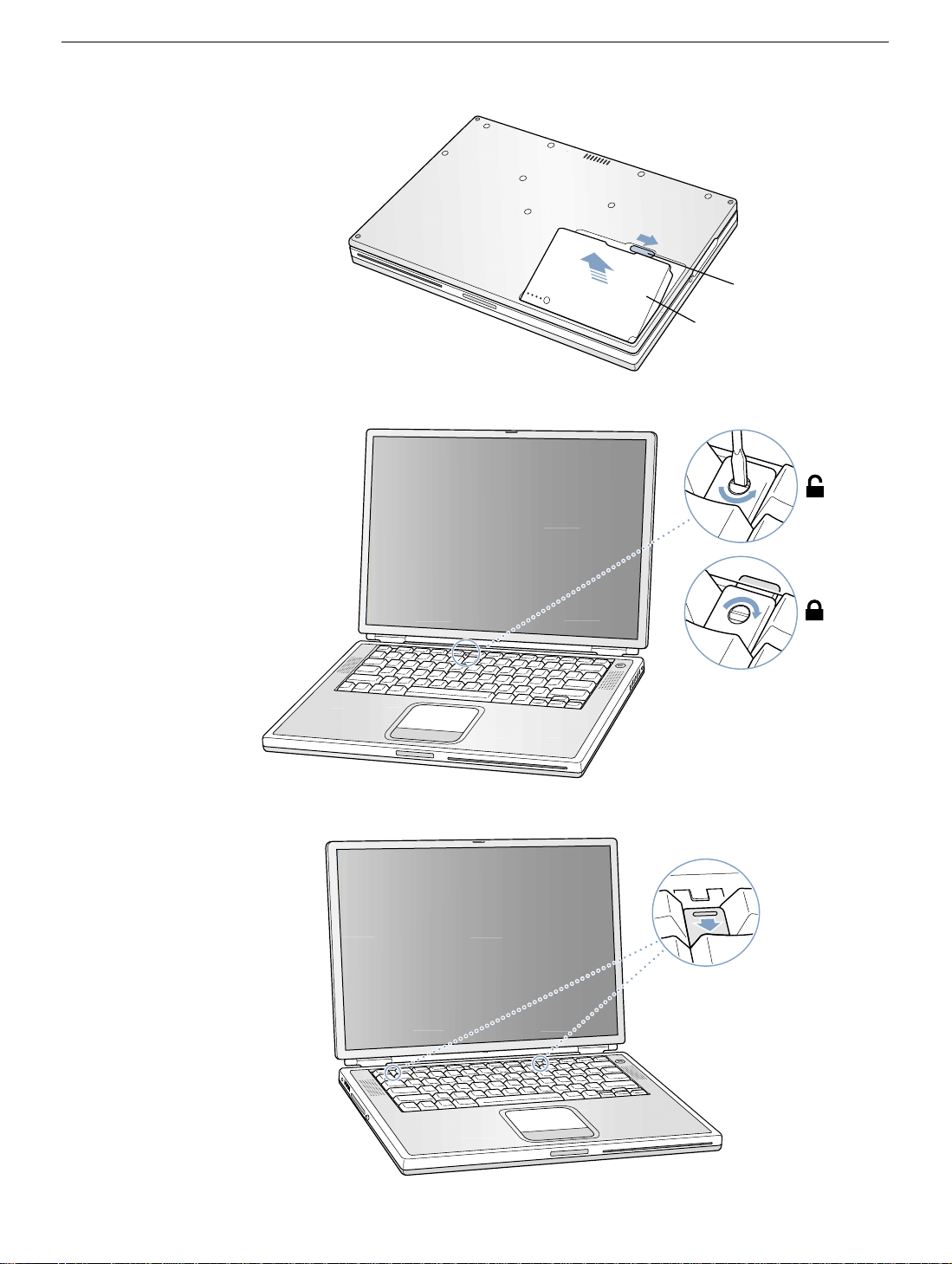
Figure 1
Figure 2
A
B
Figure 3
PowerBook G4 Keyboard -
3
Page 6
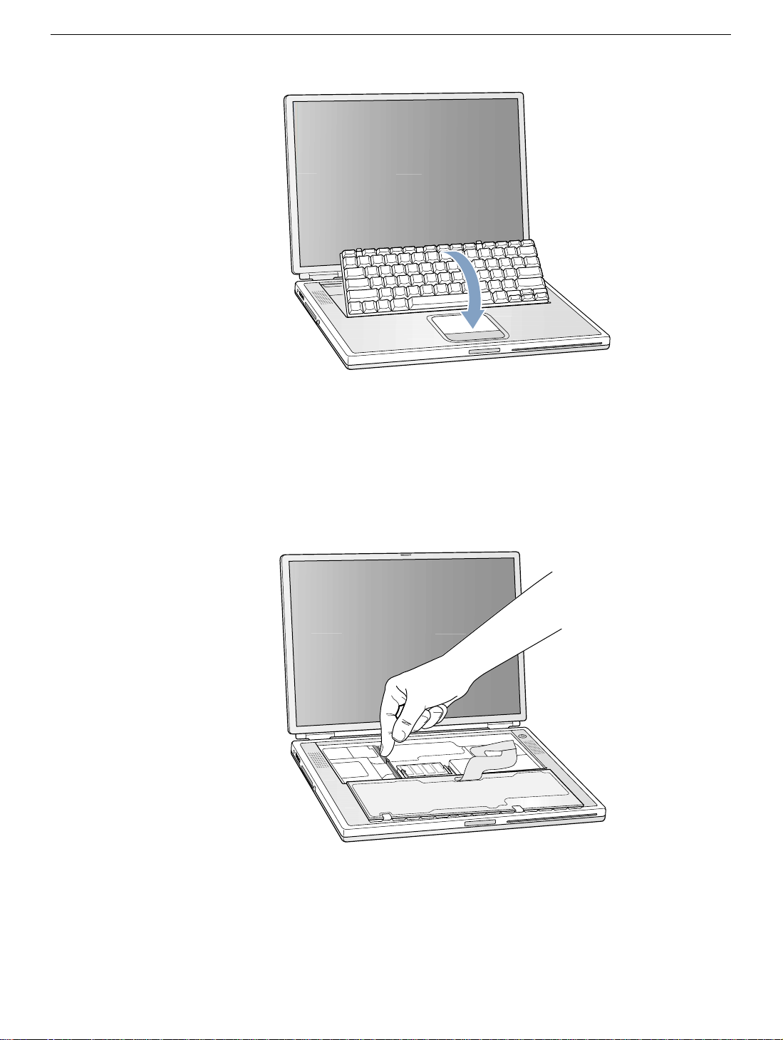
Figure 4
Figure 5
PowerBook G4 Keyboard -
4
Page 7
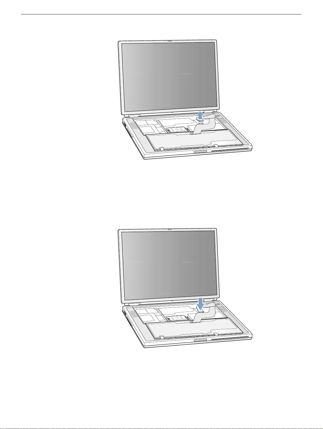
Figure 6
Figure 7
PowerBook G4 Keyboard -
5
Page 8
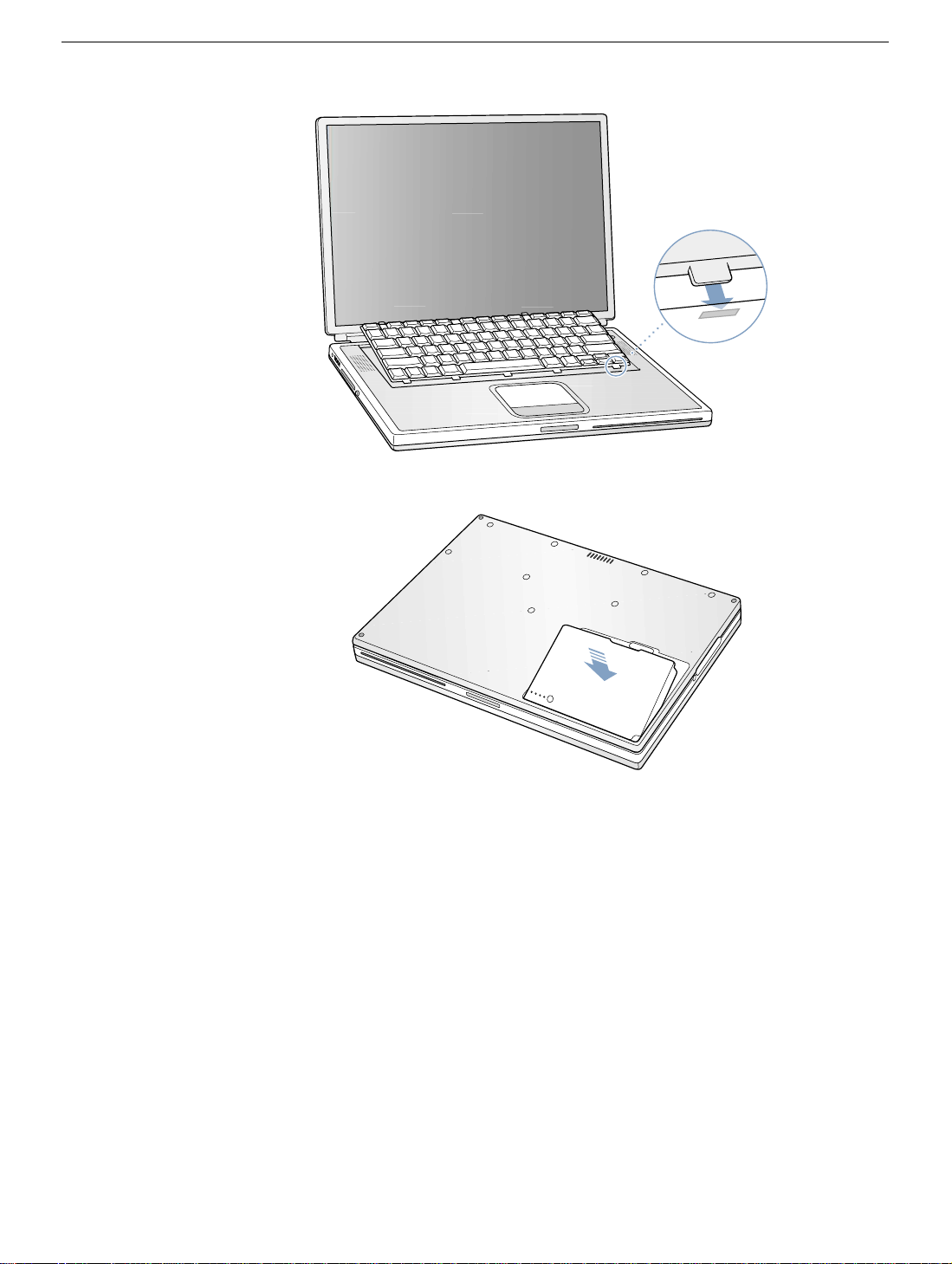
Figure 8
Figure 9
PowerBook G4 Keyboard -
6
Page 9

PowerBook G4
Memory
Replacement Instructions
Be sure to follow the instructions in this sheet carefully. Failure to follow these instructions
could result in damage to your equipment and may void your warranty.
If you are adding memory rather than replacing it, skip the section “Removing Memory
Cards.”
Note:
Written and video instructions covering customer-installable parts are available at
http://www.info.apple.com/installparts/.
Warning: Sharp edges can exist inside your computer and on any parts being
removed or installed. Use caution to avoid injury.
Tools Required
The only tool required for this procedure is a jeweler’s flat-blade screwdriver.
Memory (RAM)
Your computer comes with two memory slots, one above the other. From the factory, your
PowerBook comes with one memory card installed in the lower slot.
Note:
If desired, you can install additional memory in the upper memory slot or replace a
memory card in either slot with one of greater memory capacity, up to a maximum of a
512
megabyte (MB) memory
Warning: Memory cards come in various specifications. Only install memory cards
that are approved for your PowerBook.
card installed in each slot.
Opening the Computer
1. Place your computer on a clean, flat surface.
2. Shut down your computer. Disconnect the power cord and any other cables connected
to the computer.
Warning: Always turn off your computer before opening its case to avoid
damaging its internal components.
© 2003 Apple Computer, Inc. All rights reserved.
Page 10

3. Close the computer and turn it over. Slide the battery compartment latch
to the right to remove the battery
Removing the battery will prevent you from accidentally turning on the computer.
Warning: The internal components of your PowerBook may be hot. If you have
been using your PowerBook, wait 30 minutes after shutting down your
computer to let the internal components cool down before continuing.
4. Turn over the computer and raise the display so you can access the keyboard.
5. Make sure that the keyboard locking screw is not in the locked position
Your new PowerBook comes with the keyboard unlocked, so unless you or someone
else locked the keyboard, you can skip this step.
6. Release the keyboard by pulling down on the keyboard release tabs located to the left
of the F1 and F9 keys
toward the display to release the tabs that hold the bottom of the keyboard in place.
7. Flip over the keyboard and lay it on the palm rests and trackpad
(Figure 3)
(Figure 1B)
, then lift the top portion of the keyboard up and
.
(Figure 4)
(Figure 1A)
(Figure 2)
.
.
Perform Electrostatic Discharge
1. Touch the computer’s inside framework (a dull gray conductive composite material) to
discharge any static electricity, as shown
(Figure 5)
.
Important:
touching the computer’s framework before you touch any parts or install any
components inside the computer. To avoid static electricity building back up in your
body, do not walk around the room until you have completed your installation and
closed the computer.
To avoid electrostatic discharge damage, always ground yourself by
PowerBook G4 Memory -
2
Page 11

Removing Memory Cards
Warning: When removing or installing a memory card, do not touch its gold
connectors. Handle the card only by the edges.
1. To remove a memory card, locate the brackets that secure the card on both sides.
Carefully spread the brackets apart until the card releases on each side
The card can then be pulled up and out.
Note:
If there is a memory card in the upper memory slot
removed before removing a card in the lower slot
(Figure 6A)
(Figure 6B)
.
(Figure 6)
, it must be
Installing Memory Cards
Warning: When removing or installing a memory card, do not touch its gold
connectors. Handle the card only by the edges.
.
1. To install a memory card, hold the card at a 30-degree angle
notch in the card with the small tab in the memory slot. Then push the card into the
slot
(Figure 7)
Note:
You may feel some resistance. If you are having trouble inserting the card, try
pushing one side at a time.
2. Gently push the card down until the brackets snap onto both sides of the memory card
to lock it into place
.
(Figure 8)
.
(Figure 7A)
. Line up the
Closing the Computer
1. Verify that the keyboard connector cable is securely attached to the logic board
(Figure 9)
2. Flip the keyboard back on top of the opening and insert the tabs at the bottom of the
keyboard into the openings in the case
3. Pull down on the keyboard release tabs located to the left of the F1 and F9 keys
(Figure 3)
4. Release the tabs to secure the keyboard in place.
5. Turn over the PowerBook and replace the battery
.
(Figure 10)
and then press down on the top of the keyboard.
.
(Figure 11)
.
6. Reconnect the power cord and any other cables that were connected and restart your
computer.
Warning: Never turn on your computer unless all of its internal, external, and
case parts are securely installed. Operating the computer when its case is
open or missing parts can damage your computer or cause injury.
PowerBook G4 Memory -
3
Page 12

Figure 1
Figure 2
A
B
Figure 3
PowerBook G4 Memory -
4
Page 13
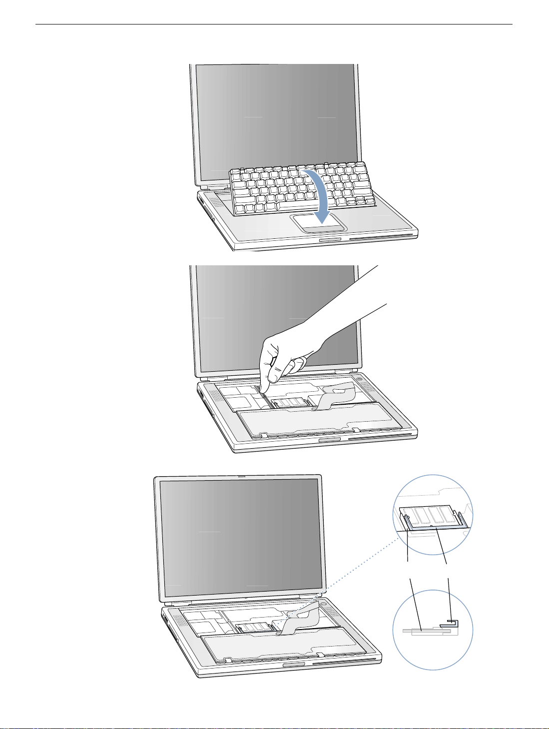
Figure 4
Figure 5
Figure 6
A
PowerBook G4 Memory -
B
5
Page 14
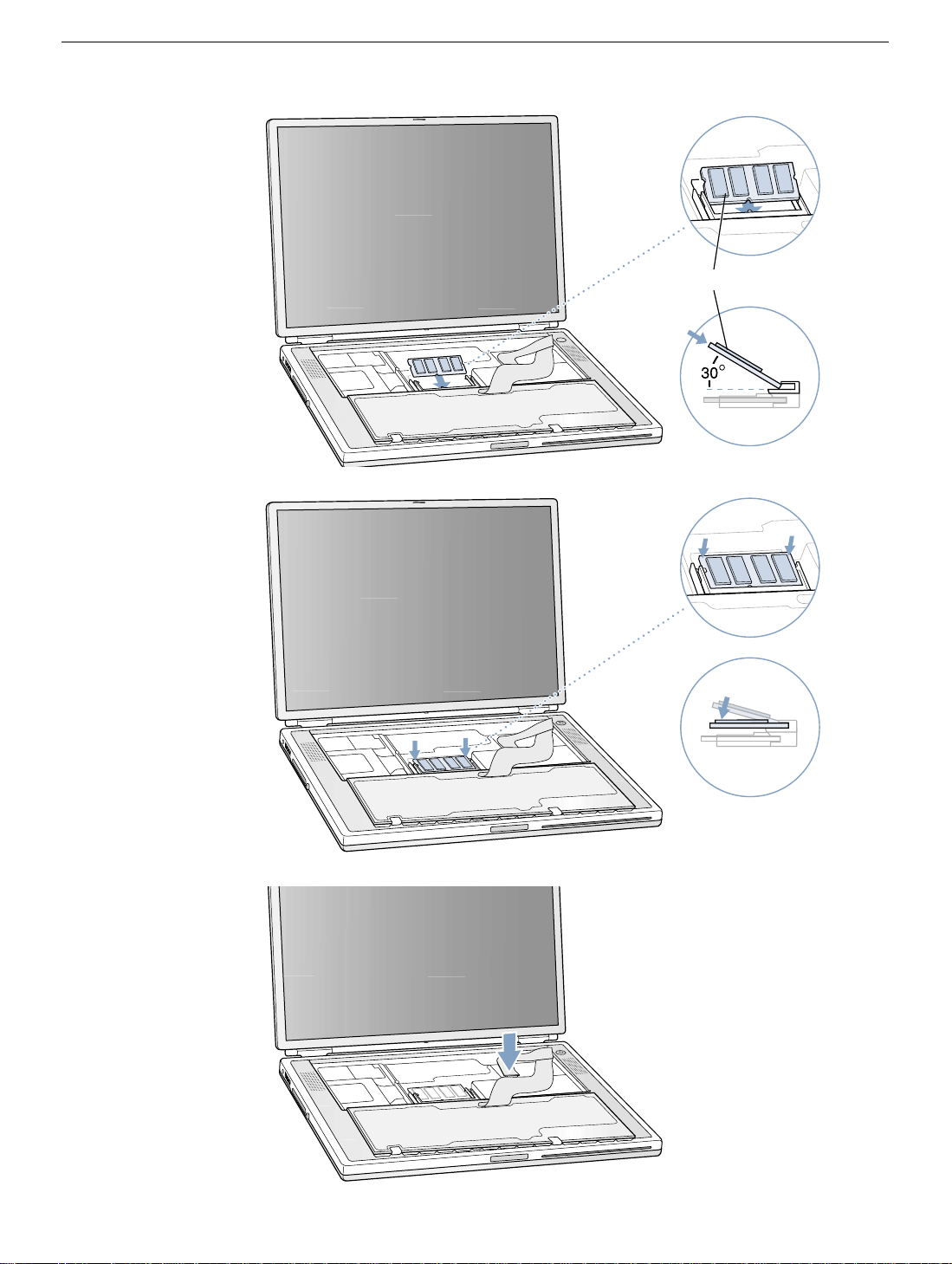
Figure 7
Figure 8
A
Figure 9
PowerBook G4 Memory -
6
Page 15
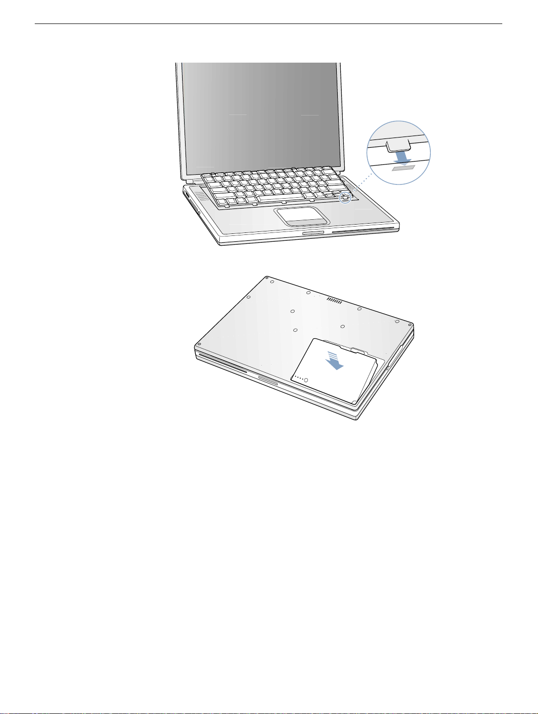
Figure 10
Figure 11
PowerBook G4 Memory -
7
Page 16

PowerBook G4
Modem
Replacement Instructions
Be sure to follow the instructions in this sheet carefully. Failure to follow these instructions
could result in damage to your equipment and may void your warranty.
Note:
Written and video instructions covering customer-installable parts are available at
http://www.info.apple.com/installparts/.
Warning: Sharp edges can exist inside your computer and on any parts being
removed or installed. Use caution to avoid injury.
Tools Required
• jeweler’s flat-blade screwdriver
• either a 5 mm wrench or socket wrench, or needle nose pliers
Opening the Computer
1. Place your computer on a clean, flat surface.
2. Shut down your computer. Disconnect the power cord and any other cables connected
to the computer.
Warning: Always turn off your computer before opening its case to avoid
damaging its internal components.
3. Close the computer and turn it over. Slide the battery compartment latch (Figure 1A)
to the right to remove the battery (Figure 1B).
Removing the battery will prevent you from accidentally turning on the computer.
Warning: The internal components of your PowerBook may be hot. If you have
been using your PowerBook, wait 30 minutes after shutting down your
computer to let the internal components cool down before continuing.
4. Turn over the computer and raise the display so you can access the keyboard.
5. Make sure that the keyboard locking screw is not in the locked position (Figure 2).
Your new PowerBook comes with the keyboard unlocked, so unless you or someone
else locked the keyboard, you can skip this step.
© 2003 Apple Computer, Inc. All rights reserved.
Page 17

6. Release the keyboard by pulling down on the keyboard release tabs located to the left
of the F1 and F9 keys (Figure 3), then lift the top portion of the keyboard up and
toward the display to release the tabs that hold the bottom of the keyboard in place.
7. Flip over the keyboard and lay it on the palm rests and trackpad (Figure 4).
Removing the Modem
1. Touch the computer’s inside framework (a dull gray conductive composite material) to
discharge any static electricity, as shown (Figure 5).
Important: To avoid electrostatic discharge damage, always ground yourself by
touching the computer’s framework before you touch any parts or install any
components inside the computer. To avoid static electricity building back up in your
body, do not walk around the room until you have completed your installation and
closed the computer.
2. Locate the modem and remove the 5 mm hexnut screw (Figure 6A).
3. Pull up on the right, front corner of the modem to disconnect it from the logic board
(Figure 7).
4. The modem must be removed carefully to avoid damaging delicate parts, including the
modem connector cable. While guiding the right front corner of the modem up and out,
carefully rotate the left side in a clockwise motion around the protruding metal tab
where the hexnut screw attached (Figure 8).
Note: The mylar sheathing around the modem may catch on this protruding tab. With
careful manipulation around the tab, the modem will come out.
5. Disconnect the modem connector cable (Figure 9).
Installing the Replacement Modem
1. Connect the modem connector cable to the modem (Figure 10).
2. Begin to insert the left side of the modem into the modem opening, then guide it
around the protruding metal tab in a counterclockwise motion (Figure 11).
The right side should then set into place and lay flat.
Note: Visually verify that the modem connector cable is still attached.
3. Press down on the front edge of the modem in the center to firmly connect it to the
logic board (Figure 12).
Note: You may need to maneuver the modem around slightly until you feel the
connectors match up.
PowerBook G4 Modem - 2
Page 18

4. Install the hexnut screw (Figure 6A). The screw hole on the modem should be aligned
with the screw flange; if not, the modem may not be properly attached to the logic
board (see step 3).
Note: It may be helpful to use a finger tip to hold the top of the screw straight and
steady while turning the screw with a tool.
Closing the Computer
1. Verify that the keyboard connector cable is securely attached to the logic board
(Figure 13).
2. Flip the keyboard back on top of the opening and insert the tabs at the bottom of the
keyboard into the openings in the case (Figure 14).
3. Pull down on the keyboard release tabs located to the left of the F1 and F9 keys
(Figure 3) and then press down on the top of the keyboard.
4. Release the tabs to secure the keyboard in place.
5. Turn over the PowerBook and replace the battery (Figure 15).
6. Reconnect the power cord and any other cables that were connected and restart your
computer.
Warning: Never turn on your computer unless all of its internal, external, and
case parts are securely installed. Operating the computer when its case is
open or missing parts can damage your computer or cause injury.
Replacing International Modems
After you have replaced a modem in Europe or Asia, open the software utility Modem
Country Selector and verify that the modem is set to the correct country. Modem Country
Selector is located in the Apple Extras folder on your hard drive or can be downloaded as
part of the Apple Modem Updater software bundle at http://asu.info.apple.com.
PowerBook G4 Modem - 3
Page 19
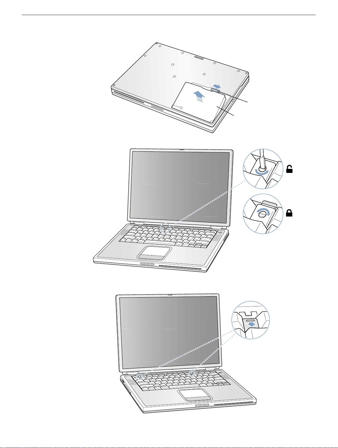
Figure 1
Figure 2
A
B
Figure 3
PowerBook G4 Modem - 4
Page 20
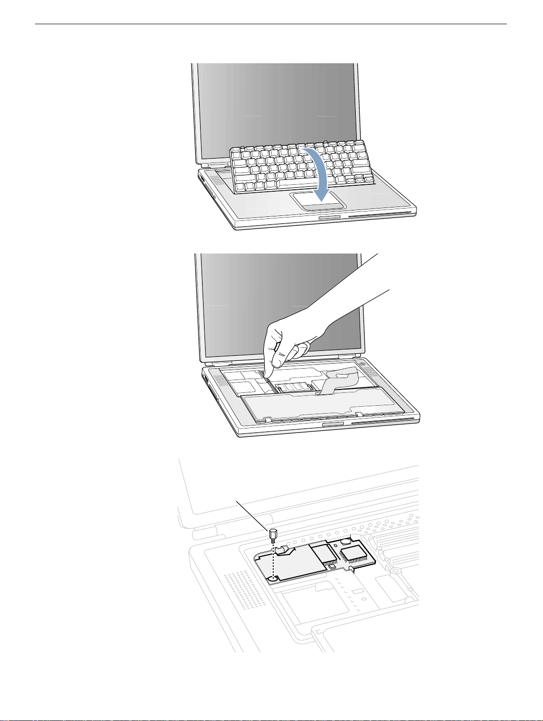
Figure 4
Figure 5
Figure 6
A
PowerBook G4 Modem - 5
Page 21
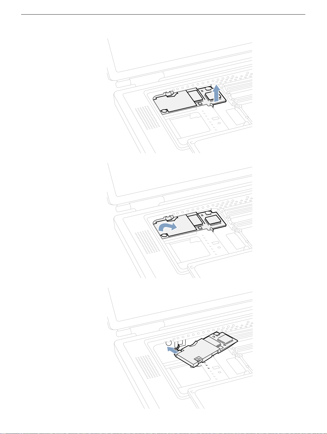
Figure 7
Figure 8
Figure 9
PowerBook G4 Modem - 6
Page 22
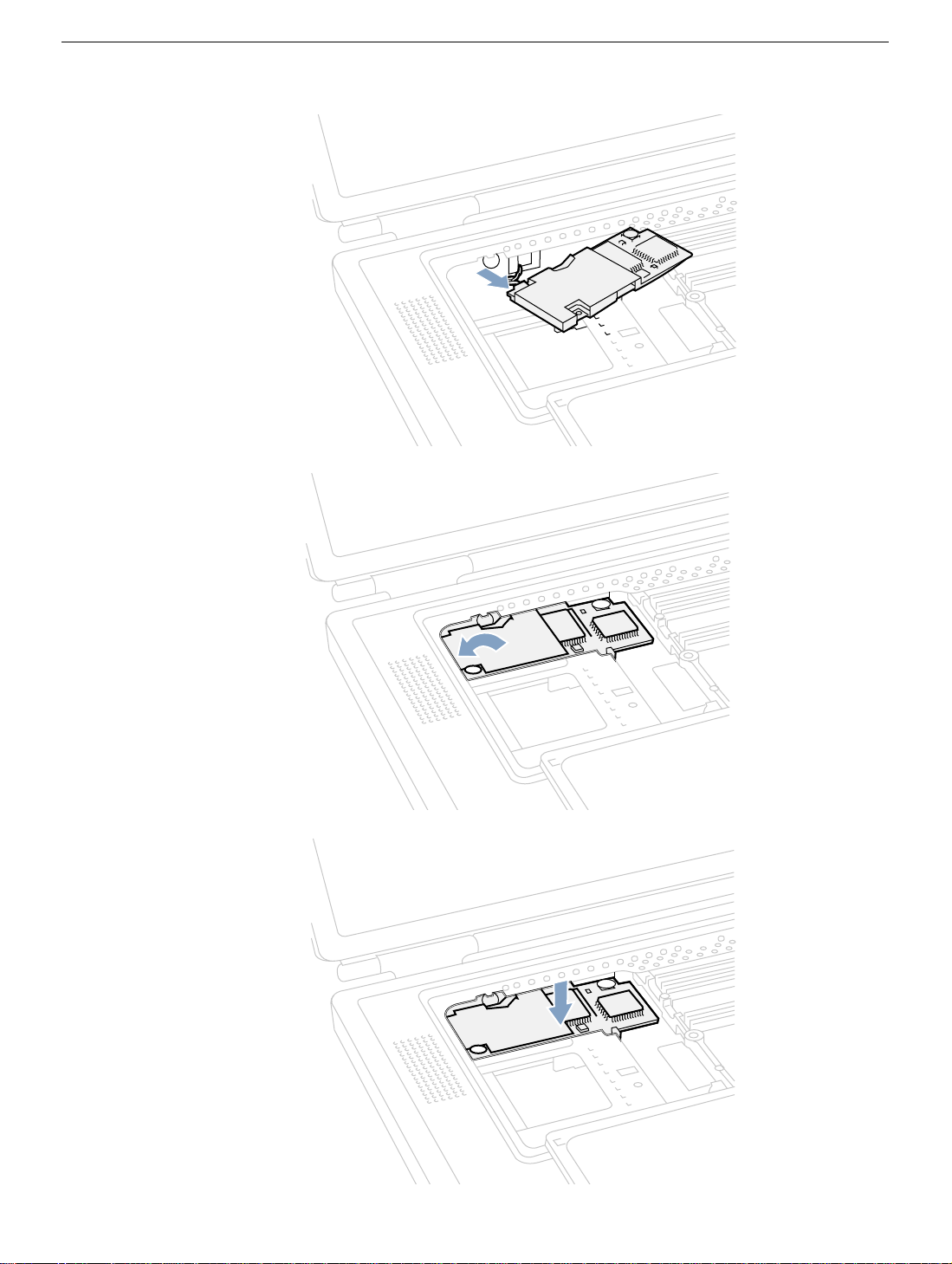
Figure 10
Figure 11
Figure 12
PowerBook G4 Modem - 7
Page 23
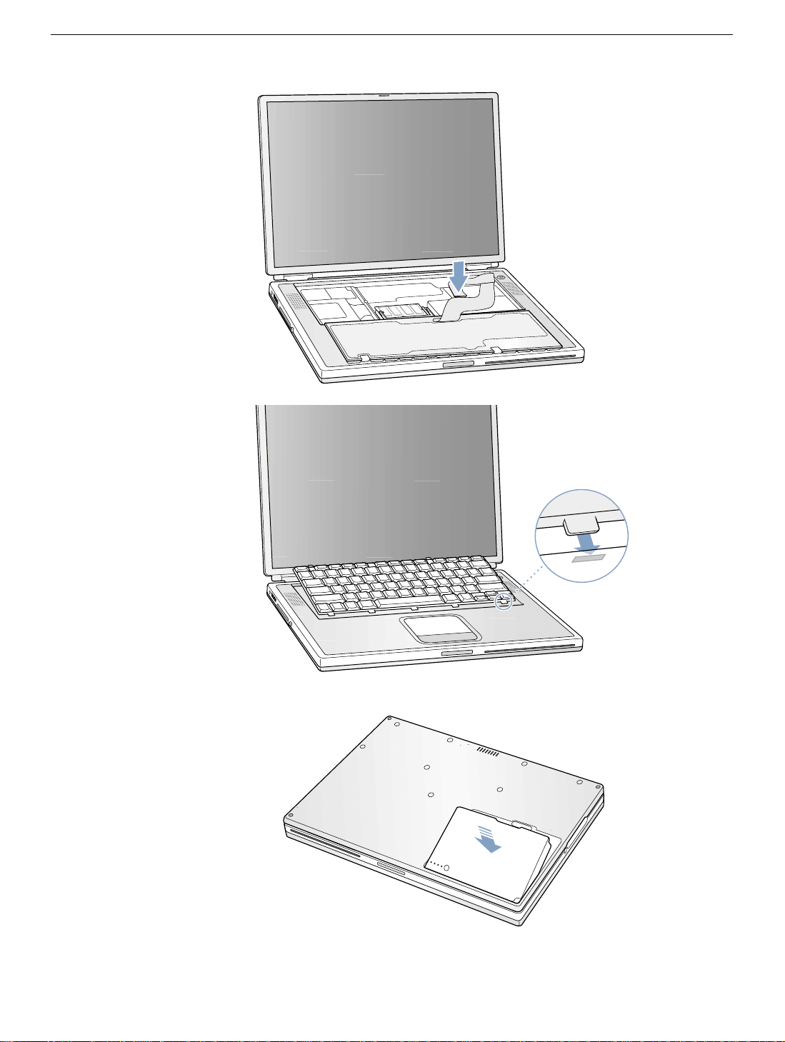
Figure 13
Figure 14
Figure 15
PowerBook G4 Modem - 8
Page 24

PowerBook G4
Bottom Case
Replacement Instructions
Be sure to follow the instructions in this sheet carefully. Failure to follow these instructions
could result in damage to your equipment and may void your warranty.
Note: Written and video instructions covering customer-installable parts are available at
http://www.info.apple.com/installparts/.
Warning: Sharp edges can exist inside your computer and on any parts being
removed or installed. Use caution to avoid injury.
Tools Required
• Phillips screwdriver
• soft towel or cloth, larger than the PowerBook
Removing the Bottom Case
1. Place your computer on a clean, flat surface.
2. Shut down your computer. Disconnect the power cord and any other cables connected
to the computer.
Warning: Always turn off your computer before opening its case to avoid
damaging its internal components.
Warning: The internal components of your PowerBook may be hot. If you have
been using your PowerBook, wait 30 minutes after shutting it down to let the
internal components cool before continuing.
3. Place a towel or soft cloth on a table in front of you (Figure 1A). The towel or cloth will
protect the keyboard and display area of the PowerBook when you flip it over to
remove the bottom case. Make sure it covers an area large enough for your
PowerBook and that it hangs over the edge of the table.
4. With the display open at an angle greater than 90 degrees, carefully flip the
PowerBook over and lay it flat, fully on the table. Make sure the display hangs over the
edge of the table and rests lightly on your lap (Figure 1B).
© 2003 Apple Computer, Inc. All rights reserved.
Page 25

5. Slide the battery compartment latch (Figure 2A) to remove the battery (Figure 2B).
Make sure to return the battery latch fully to the right.
Removing the battery will help you remove the bottom case and prevent you from
accidentally turning on the computer.
6. Using a Phillips screwdriver, remove the eight screws that secure the bottom case to
the PowerBook, in the order shown (Figure 3).
Important: To avoid damaging the case, be careful that the screwdriver tip does not
slip out of the screw head during removal.
7. To remove the bottom case you will need to disengage it at the left and right sides,
then carefully pivot it forward to release a retaining clip near the DVD drive slot, as
follows.
Important: Do not push on the rubber feet of the bottom case.
At the left side, carefully slide the bottom case slightly up and away from you by
pushing on it just above the hinge of the display (Figure 4), and at the same time
from within the battery compartment, pushing away from you on the edge of the
bottom case, until the left side releases.
At the right side, again carefully slide the bottom case slightly up and away from you
by pushing it just above the hinge of the display (Figure 5), and at the same time
from within the battery compartment, pushing away from you at the right-most edge
of the bottom case, until the right side releases.
8. When both the left and right sides have released, carefully pull up on the bottom case
at the edge that is closest to you and rotate it away from you, pivoting evenly over the
front edge to release a retaining clip that is located near the DVD drive slot (Figure 6).
Important: Do not force, twist or pry the bottom case if it binds or resists. The case
should remove easily. If not, follow step 7 again, until the case releases.
PowerBook G4 Bottom Case - 2
Page 26

Installing the Bottom Case
1. To attach the bottom case, align the notches on the right and left sides of the case
(some of these can be viewed through the battery opening). Then press down and
toward you slightly to secure the case (Figure 7).
Verify that the case lies flat and fits properly around the battery latch and that the
alignment tab that protrudes on the underside of the bottom case (Figure 7A), has
seated properly.
The case edges should line up smoothly.
Note: Applying pressure to the bottom case at the back of the battery compartment
opening, near the latch, and on the front and back outside edges of the case can help
with alignment.
2. Check that the eight screw holes on the case align with the holes on the computer.
Verify that the display rests on your lap as shown (Figure 1B).
3. Replace the eight screws in the order shown (Figure 7). Do not overtighten or
damage could result.
Note: The screws must go in straight and easily; if not, readjust the bottom case for
proper alignment.
Important: To avoid damaging the case, be careful that the screwdriver tip does not
slip out of the screw head during tightening.
4. Replace the battery.
5. Turn the computer over so that the DVD slot (Figure 8A) faces you. Just below the
center of the DVD slot, verify that the bottom case is flush with the front edge of the
slot. If the case is slightly bowed and there is a gap (Figure 8B), carefully pull the
bottom edge of the DVD slot until it clicks into place and becomes flush with the
bottom case.
6. Reconnect the power cord and any other cables that were connected and restart your
computer.
Warning: Never turn on your computer unless all of its internal, external, and
case parts are securely installed. Operating the computer when its case is
open or missing parts can damage your computer or cause injury.
PowerBook G4 Bottom Case - 3
Page 27
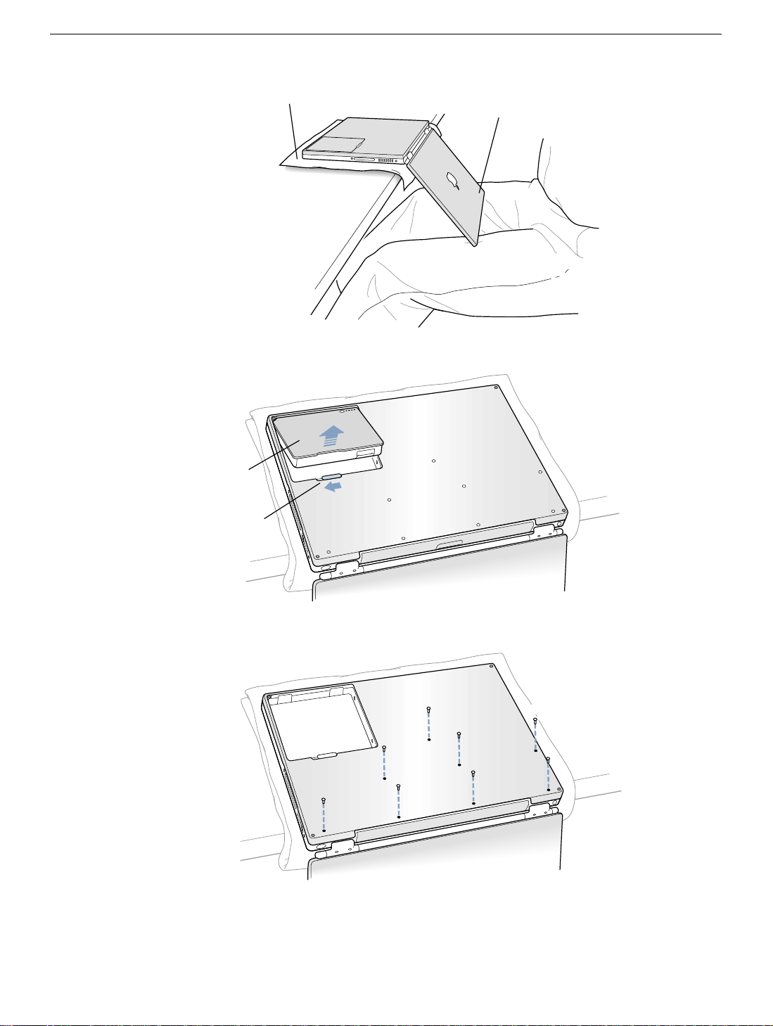
Figure 1
Figure 2
A
B
B
Figure 3
A
1
3
2
8
7
6
4
5
PowerBook G4 Bottom Case - 4
Page 28
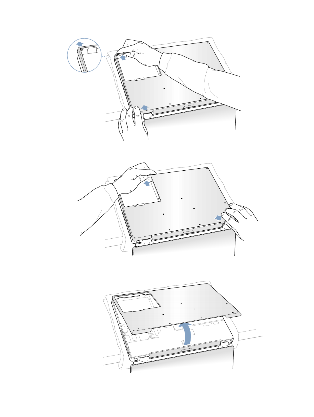
Figure 4
Figure 5
Figure 6
PowerBook G4 Bottom Case - 5
Page 29
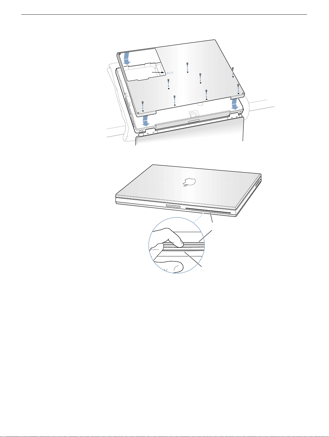
Figure 7
Figure 8
8
A
7
1
3
6
2
A
5
4
B
PowerBook G4 Bottom Case - 6
Page 30

PowerBook G4
AirPort Card
Replacement Instructions
Be sure to follow the instructions in this sheet carefully. Failure to follow these instructions
could result in damage to your equipment and may void your warranty.
If you are adding an AirPort Card rather than replacing one, skip the section “Removing
the AirPort Card.”
Note: Written and video instructions covering customer-installable parts are available at
http://www.info.apple.com/installparts/.
Warning: Sharp edges can exist inside your computer and on any parts being
removed or installed. Use caution to avoid injury.
Tools Required
• Phillips screwdriver
• soft towel or cloth, larger than the PowerBook
Opening the Computer
1. Place your computer on a clean, flat surface.
2. Shut down your computer. Disconnect the power cord and any other cables connected
to the computer.
Warning: Always turn off your computer before opening its case to avoid
damaging its internal components.
Warning: The internal components of your PowerBook may be hot. If you have
been using your PowerBook, wait 30 minutes after shutting it down to let the
internal components cool before continuing.
3. Place a towel or soft cloth on a table in front of you (Figure 1A). The towel or cloth will
protect the keyboard and display area of the PowerBook when you flip it over to
remove the bottom case. Make sure it covers an area large enough for your
PowerBook and that it hangs over the edge of the table.
© 2003 Apple Computer, Inc. All rights reserved.
Page 31

4. With the display open at an angle greater than 90 degrees, carefully flip the
PowerBook over and lay it flat, fully on the table. Make sure the display hangs over the
edge of the table and rests lightly on your lap (Figure 1B).
5. Slide the battery compartment latch (Figure 2A) to remove the battery (Figure 2B).
Make sure to return the battery latch fully to the right.
Removing the battery will help you remove the bottom case and prevent you from
accidentally turning on the computer.
6. Using a Phillips screwdriver, remove the eight screws that secure the bottom case to
the PowerBook, in the order shown (Figure 3).
Important: To avoid damaging the case, be careful that the screwdriver tip does not
slip out of the screw head during removal.
7. To remove the bottom case you will need to disengage it at the left and right sides,
then carefully pivot it forward to release a retaining clip near the DVD drive slot, as
follows.
Important: Do not push on the rubber feet of the bottom case.
At the left side, carefully slide the bottom case slightly up and away from you by
pushing on it just above the hinge of the display (Figure 4), and at the same time
from within the battery compartment, pushing away from you on the edge of the
bottom case, until the left side releases.
At the right side, again carefully slide the bottom case slightly up and away from you
by pushing it just above the hinge of the display (Figure 5), and at the same time
from within the battery compartment, pushing away from you at the right-most edge
of the bottom case, until the right side releases.
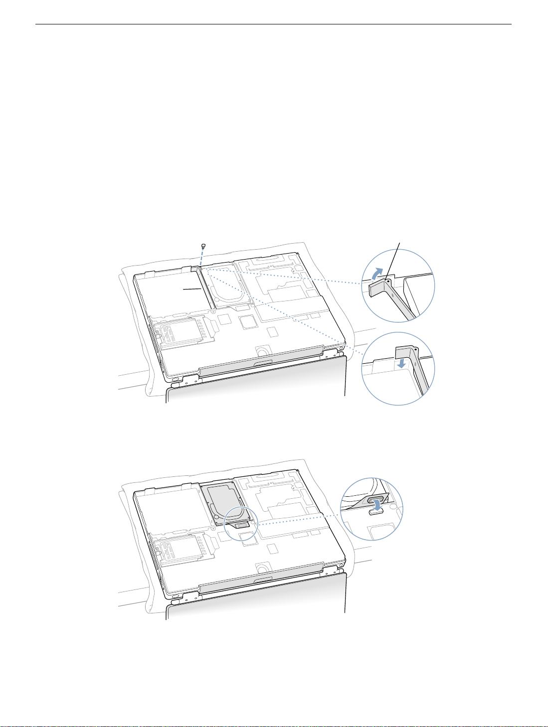
8. When both the left and right sides have released, carefully pull up on the bottom case
at the edge that is closest to you and rotate it away from you, pivoting evenly over the
front edge to release a retaining clip that is located near the DVD drive slot (Figure 6).
Important: Do not force, twist or pry the bottom case if it binds or resists. The case
should remove easily. If not, follow step 7 again, until the case releases.
9. Touch the computer’s inside framework (a dull gray conductive composite material) to
discharge any static electricity, as shown (Figure 7).
Important: To avoid electrostatic discharge damage, always ground yourself by
touching the computer’s framework before you touch any parts or install any
components inside the computer. To avoid static electricity building back up in your
body, do not walk around the room until you have completed the installation and
closed the computer.
PowerBook G4 AirPort Card - 2
Page 32

Removing the AirPort Card
1. Pull back on the antenna clip (Figure 8A) to release the antenna cable connector
(Figure 8B) and allow the card to rise up slightly, then pull the card from the AirPort
connector (Figure 8D).
Hold the AirPort Card with one hand and grasp the antenna cable connector with the
other. While being careful not to strain the antenna cable (Figure 8C), firmly pull the
connector straight out of the AirPort Card.
Important: If an AirPort Card is not being reinstalled right away, the antenna cable
connector must be replaced into its holder (Figure 10B) and the loop of the antenna
cable pulled up slightly and away from the edge of the computer case. This prevents
the cable from interfering with the PC card slot, below, or getting pinched during
reassembly.
Also, if the insertion end of the AirPort Card connector is rotated up, push it down into
the level position. This allows the bottom case to install properly.
Installing the AirPort Card
1. If the AirPort Card to be installed came with the AirPort adapter (Figure 9A), remove
the metal clip (Figure 9B) and pull the AirPort Card (Figure 9C) from the adapter.
(The adapter and metal clip are not used with your PowerBook.)
2. If this is a new installation, pull out the AirPort antenna cable connector (Figure 10A)
from its holder (Figure 10B).
3. Pull up on the top part of the AirPort Card connector (Figure 11B) at the insertion end
to raise it up slightly, if it is not already up.
4. Position the AirPort Card (Figure 11A) with the AirPort ID numbers and bar code
facing up and slide the card into the connector. Make sure to slide the card all the way
in until the card is securely attached to the connector.
5. Plug the antenna cable connector (Figure 12A) into the port, which is located just
below the plastic tab (Figure 12F), on the end of the AirPort Card. Make sure the
connector is straight before inserting it into the card.
6. Push the AirPort Card down into its space until the antenna cable connector is
secured by the small antenna clip (Figure 12B).
Important: Route the antenna cable (Figure 12C) between the edge of the computer
(Figure 12D) and the AirPort Card. Verify that the cable is away from the edge of the
computer so that it will not be pinched during reassembly and that it does not sag
down into the PC card slot area (below the AirPort Card). Take up any extra cable by
tucking it in where shown (Figure 12E).
PowerBook G4 AirPort Card - 3
Page 33

7. Fold the plastic tab (Figure 12F) on the AirPort Card over the top of the card.
Note: The plastic tab must be folded over the card during the installation of the
bottom case, otherwise you will not be able to securely attach the bottom case to the
computer.
Closing the Computer
1. To attach the bottom case, align the notches on the right and left sides of the case
(some of these can be viewed through the battery opening). Then press down and
toward you slightly to secure the case (Figure 13).
Verify that the case lies flat and fits properly around the battery latch and that the
alignment tab that protrudes on the underside of the bottom case (Figure 13A), has
seated properly.
The case edges should line up smoothly.
Note: Applying pressure to the bottom case at the back of the battery compartment
opening, near the latch, and on the front and back outside edges of the case can help
with alignment.
2. Check that the eight screw holes on the case align with the holes on the computer.
Verify that the display rests on your lap as shown (Figure 1B).
3. Replace the eight screws in the order shown (Figure 13). Do not overtighten or
damage could result.
Note: The screws must go in straight and easily; if not, readjust the bottom case for
proper alignment.
Important: To avoid damaging the case, be careful that the screwdriver tip does not
slip out of the screw head during tightening.
4. Replace the battery.
5. Turn the computer over so that the DVD slot (Figure 14A) faces you. Just below the
center of the DVD slot, verify that the bottom case is flush with the front edge of the
slot. If the case is slightly bowed and there is a gap (Figure 14B), carefully pull the
bottom edge of the DVD slot until it clicks into place and becomes flush with the
bottom case.
6. Reconnect the power cord and any other cables that were connected and restart your
computer.
Warning: Never turn on your computer unless all of its internal, external, and
case parts are securely installed. Operating the computer when its case is
open or missing parts can damage your computer or cause injury.
PowerBook G4 AirPort Card - 4
Page 34

Figure 1
Figure 2
A
B
B
Figure 3
A
1
3
2
8
7
6
4
5
PowerBook G4 AirPort Card - 5
Page 35

Figure 4
Figure 5
Figure 6
PowerBook G4 AirPort Card - 6
Page 36

Figure 7
Figure 8
D
C
Figure 9
A
B
A
C
B
PowerBook G4 AirPort Card - 7
Page 37

Figure 10
B
A
Figure 11
A
B
Figure 12
E
D
C
B
A
F
PowerBook G4 AirPort Card - 8
Page 38

Figure 13
Figure 14
8
A
7
1
3
6
2
A
5
4
B
PowerBook G4 AirPort Card - 9
Page 39

PowerBook G4
Hard Drive
Replacement Instructions
Follow the instructions in this sheet carefully. Failure to follow these instructions could
damage your equipment and void its warranty.
Note: Written and video instructions covering customer-installable parts are available at
http://www.info.apple.com/installparts/.
Warning: Sharp edges can exist inside your computer and on any parts being
removed or installed. Use caution to avoid injury.
During this procedure, keep small parts away from children.
Tools Required
• Soft towel or cloth, larger than the PowerBook
• Phillips screwdriver, size 1
• Torx T8 screwdriver (provided with hard drive)
Backing Up Your Data
Warning: Before replacing your hard drive, make sure you back up all data on the
drive.
Opening the Computer
Warning: Always shut down your computer before opening it to avoid damaging its
internal components or causing injury. After you shut down the computer, the
internal components can be very hot. Let the computer cool down before
continuing.
To access the hard drive, you must first remove the battery and bottom case.
1. Place your computer on a clean, flat surface.
2. Shut down your computer and wait thirty minutes before continuing.
3. Disconnect the power cord and any other cables connected to the computer.
© 2003 Apple Computer, Inc. All rights reserved.
Page 40

4. Place a towel or soft cloth on a table in front of you. (Figure 1A)
The towel or cloth will protect the keyboard and display area of the PowerBook when
you flip it over to remove the battery and bottom case. Make sure it covers an area
large enough for your PowerBook and that it hangs over the edge of the table.
5. With the display open at an angle greater than 90 degrees, carefully flip the
PowerBook over and lay it flat, fully on the table. Make sure the display hangs over the
edge of the table and rests lightly on your lap. (Figure 1B)
Important: Do not open the display farther than the angle shown.
Figure 1
A
B
6. Remove the battery by sliding the battery latch to the left. Make sure to return the latch
fully to the right. (Figure 2)
Removing the battery will prevent you from accidentally turning on the computer.
Warning: Removing the battery before shutting down your computer may
result in data loss.
Figure 2
PowerBook G4 Hard Drive - 2
Page 41

7. Use a Phillips screwdriver to remove the eight bottom case screws in the order shown.
(Figure 3)
Important: To avoid damaging the case, be careful that the screwdriver tip does not
slip out of the screw head during removal.
Figure 3
1
3
2
8
7
6
4
5
Note: In the following two steps you will disengage the left and right sides of the bottom
case and then pivot it forward to remove.
8. Carefully slide the bottom case away from you. (Figure 4)
Important: Do not push on the rubber feet of the bottom case.
Figure 4
PowerBook G4 Hard Drive - 3
Page 42

9. Pivot the bottom case up as shown. (Figure 5)
Figure 5
10. Touch the computer’s inside framework (a dull gray conductive composite material) to
discharge any static electricity, as shown. (Figure 6)
Important: To avoid electrostatic discharge damage, always ground yourself by
touching the computer’s framework before you touch any parts or install any
components inside the computer. To avoid static electricity building back up in your
body, do not walk around the room until you have completed your installation and
closed the computer.
Figure 6
PowerBook G4 Hard Drive - 4
Page 43
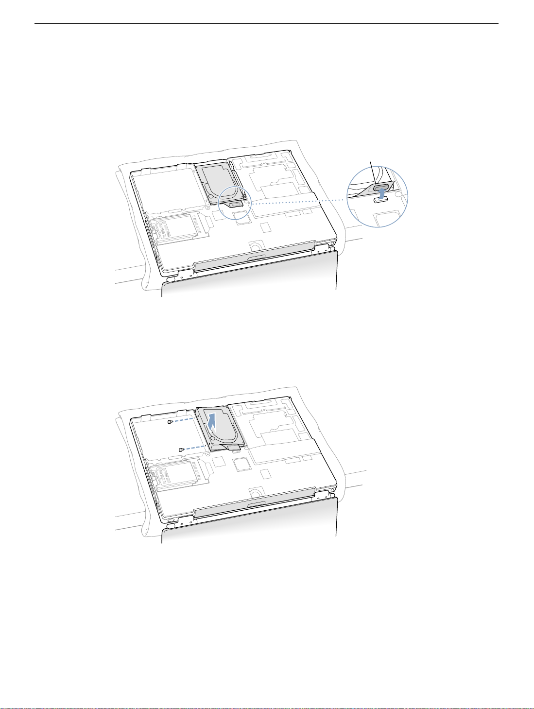
Removing the Installed Hard Drive
1. With your fingers, carefully pry up the hard drive flex cable connector (Figure 7A) at
its sides to disconnect it from the logic board. You may need to pry one side, then the
other, in a rocking motion.
Figure 7
A
2. With a Torx T8 screwdriver, remove the two screws (Figure 8) that secure the hard
drive to the mounting bracket and then gently remove the hard drive.
Important: Do not pull on the flex cable or use the cable as a handle.
Figure 8
Note: There are four rubber stoppers on the hard drive that fit over screws (two on
each side). Remove any that may have fallen off or that remain in the holes in the
mounting bracket inside the computer.
3. If not included with the replacement drive, remove the Mylar sheath and the flex cable
to transfer to the replacement drive.
Important: The connector pins on the hard drive are fragile and bend easily. Use
care to keep the pins straight when removing or installing the flex cable.
PowerBook G4 Hard Drive - 5
Page 44

Installing the Replacement Hard Drive
Warning: To avoid potential injury, avoid touching or brushing against the thin strip
of metal that extends up from the hard drive mounting bracket (Figure 9A).
Important: Avoid touching the optical drive as you perform this procedure.
1. With a Torx T8 screwdriver, remove the screw from the top of the hard drive mounting
bracket. (Figure 9B)
2. Carefully lift the mounting bracket up (Figure 9C) and gently bend it around the first
battery bay tab (Figure 9D). The tab holds the bracket out of the way.
Warning: Lift the bracket just high enough to clear the battery bay tab. If you
lift the bracket higher than the tab you risk damaging the bracket, and such
damage is not covered by the limited warranty on your computer.
Figure 9
B
D
A
C
PowerBook G4 Hard Drive - 6
Page 45

3. Make sure that the screws (Figure 10A) and rubber stoppers (Figure 10B) are in
place on the sides of the replacement drive.
4. Install the Mylar sheath (Figure 10C) so that it covers the bottom and left and right
sides of the drive. The sheath is directional and must be installed in the direction that
does not extend beyond the front of the drive.
5. Carefully install the flex cable to the hard drive, if needed, (Figure 10D). The
connector is keyed to fit only one way.
Figure 10
B
C
D
A
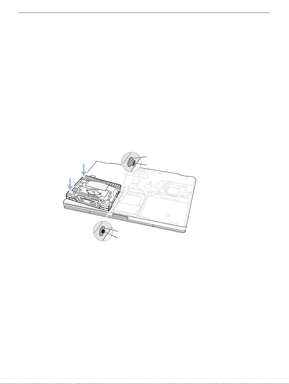
6. Insert the right side of the drive first, until the rubber stoppers fit securely into the
holes in the bracket, and then insert the left side of the drive. (Figure 11)
Note: Make sure that the rubber stoppers do not fall off during installation.
Important: Make sure that the flex cable does not get pinched behind the drive
during installation.
Figure 11
PowerBook G4 Hard Drive - 7
Page 46
7. Lift the mounting bracket (Figure 12A) over the battery bay tab and lower it to its
original position. Line up the rubber stoppers on the hard drive until they fully seat into
the holes in the bracket.
Note: To help with alignment, the Torx T8 screwdriver can be inserted into the screws
on the hard drive through the holes in the mounting bracket.
Important: Verify that the bottom of the mounting bracket clears and seats behind a
thin metal ridge located along the bottom of the battery compartment. (Figure 12B)
8. Replace the screw (Figure 12C) in the top of the mounting bracket, being careful not
to overtighten it.
Figure 12
C
B
A
9. Connect the hard drive’s flex cable connector (Figure 13) to the logic board.
Figure 13
PowerBook G4 Hard Drive - 8
Page 47

Closing the Computer
1. To attach the bottom case, align the notches on the right and left sides of the case,
then press down slightly to secure the case. Check the alignment of the eight screw
holes to make sure the bottom case is properly positioned.
Important: Make sure that the seams between the bottom case and the frame are
closed. Check the outside edges and around the battery well. Verify that the
alignment tab on the underside of the bottom case (Figure 14A) has seated, and the
case lies flat.
2. Replace the eight screws in the order shown. (Figure 14)
Note: The screws must go in straight and easily; if they do not, readjust the bottom
case for proper alignment. Do not overtighten the screws or damage could result.
Important: To avoid damaging the case, be careful that the screwdriver tip does not
slip out of the screw head during tightening.
Figure 14
8
A
7
1
3
6
2
5
4
PowerBook G4 Hard Drive - 9
Page 48

3. Replace the battery. (Figure 15)
Important: Make sure that the battery locks securely into place and that the battery
latch is slid all the way into the locked position.
Figure 15
4. Turn the computer over. Look at the optical drive slot to make sure that the case is
properly secured. If a gap exists below the slot, gently pull the bottom of the optical
drive slot toward you until it clicks into place and the gap is removed. (Figure 16)
Figure 16
®
PowerBook G4 Hard Drive - 10
Page 49

5. Reconnect the power cord and any other cables that were connected, and restart your
computer.
Warning: Never turn on your computer unless all of its internal and external
parts are in place and it is closed. Operating the computer when it is open or
missing parts can damage your computer or cause injury.
6. Restore the data from your backup to the new drive.
7. Check the operation of the optical drive. If the hard drive is installed incorrectly, the
optical drive mechanism might not spin correctly and will result in mechanical noise
when playing a disc.
PowerBook G4 Hard Drive - 11
Page 50

PowerBook G4
DVD-ROM Drive
Replacement Instructions
The following instructions explain how to replace the DVD-ROM drive in the PowerBook
G4 computer.
Tools
• Soft towel or cloth, larger than the PowerBook
• Black stick (or other nonconductive nylon or plastic tool)
Preliminary Steps
Before you begin, remove the following:
• Battery
• Keyboard
• Bottom case
© 2003 Apple Computer, Inc. All rights reserved.
Page 51

Procedure
1. With the computer on a soft cloth, locate the adhesive dust cover, a black plastic sheet
that holds the PMU and DVD ribbon cables in place.
Warning: The adhesive dust cover adheres to the thin, plastic DVD drive
sleeve. Removing the dust cover too quickly might cause the sleeve to tear,
exposing the DVD drive mechanism.
2. Starting at one corner, slowly and carefully peel off the adhesive dust cover. If the dust
cover sticks too firmly to the drive sleeve, use a black stick or other nonconductive tool
to gently separate the dust cover from the sleeve. Discard the adhesive dust cover
when you have removed it.
Important: When reassembling the computer, apply a new dust cover after
the replacement DVD-ROM drive is installed.
®
Adhesive Dust Cover
3. To protect the display, lay a soft cloth between the display and the top case. Then
close the computer and turn it over.
PowerBook G4 DVD-ROM Drive - 2
Page 52

4. Warning: The drive is a sensitive device and should be handled carefully to
avoid damage. Handle the drive only by the corners or the back end of the drive,
as indicated by the safe areas shown below. Do not place anything on top of the
drive nor press on the body of the drive. If mishandled, the alignment of the
drive frame could be altered, resulting in issues with disk mounting, disk
insertion, or disk ejection.
5. With your fingers or a black stick, carefully pry up the DVD drive connector at its sides
to disconnect it from the logic board. You may need to pry one side then the other in a
rocking motion.
Note: If tape is covering the connector, carefully pull it out of the way just enough to
remove the connector. Reuse the tape when installing the replacement drive.
Important: Do not pull on the connector cable or use as a handle.
DVD Drive Connector
DVD Drive Connector Cable
PowerBook G4 DVD-ROM Drive - 3
Page 53

6. Holding the corners on the left side of the drive, pull up on the DVD drive until it
releases from the computer.
Note: There are four rubber mounts (two on each side) on the DVD drive that are
held by friction on the screws. Remove any that may have fallen off inside the
computer.
7. Before installing the replacement drive, verify that the small, metal EMI clip,
normally located between the PMU cable and the DVD cable, is securely attached to
the frame rib. If the EMI clip is loose, bend it down to secure it to the rib. Check both
ends of the clip to ensure it is held in place.
PowerBook G4 DVD-ROM Drive - 4
Page 54
8. Install the replacement DVD-ROM drive (noting the additional instructions below), and
reassemble and test the computer.
When reassembling the computer, verify that there are two screws with rubber
mounts on both the right and left side of the drive.
Note: The rubber mount at the front right corner of the drive is shorter than the other
three rubber mounts.
Starting with the side of the carrier closest to the hard drive, carefully guide the
rubber mounts on the side of the DVD drive into the two holes on the frame rib next
to the hard drive. Push down on the DVD drive corners to secure the drive.
Note: Make sure that the rubber mounts do not fall off during installation.
Important: Make sure that the connector cable does not get pinched behind the drive
during installation.
Rubber Mount
Screw
Rubber Mount
Screw
PowerBook G4 DVD-ROM Drive - 5
Page 55

PowerBook G4
PMU Card
Replacement Instructions
The following instructions explain how to replace the PMU (Power Management Unit) card
in the PowerBook G4 computer.
Tools
• Soft towel or cloth, larger than the PowerBook
• Black stick (or other nonconductive nylon or plastic tool)
Preliminary Steps
Before you begin, remove the following:
• Battery
• Keyboard
• Bottom case
• DVD-ROM drive
© 2003 Apple Computer, Inc. All rights reserved.
Page 56

Procedure
Important: Some of the internal cables are held in place by transparent orange Kapton
tape. Note the orientation of the tape before removing it, and reserve the tape to use again
for the replacement PMU card connections.
1. Carefully peel away the tape so you can disconnect the backup battery connector
from the PMU card.
Important: When reassembling the computer, make sure the connected backup
battery cable is routed at an approximate 90-degree angle, as shown.
Note: When reassembling the computer, apply the tape to both the battery cable
and the single, black, wireless antenna cable.
PowerBook G4 PMU Card - 2
Page 57

2. Disconnect the ribbon cable at J1.
3. Disconnect the ribbon cable at J5.
4. From the left corner of the card, raise the metal clip out of the hole in the PMU card.
Pivot the card clockwise slightly to free the PMU card from the metal clip and the metal
tab at the side of the card.
5. Install the replacement PMU card, and reassemble and test the computer.
PowerBook G4 PMU Card - 3
Page 58

PowerBook G4
Backup Battery
Replacement Instructions
The following instructions explain how to replace the backup battery in the PowerBook G4
computer.
Tools
• Soft towel or cloth, larger than the PowerBook
• Black stick (on other nonconductive nylon or plastic tool)
Preliminary Steps
Before you begin, remove the following:
• Battery
• Keyboard
• Bottom case
• DVD-ROM drive
© 2003 Apple Computer, Inc. All rights reserved.
Page 59

Procedure
1. Notice that the backup battery cable and the single, black wireless antenna cable are
held in place by transparent orange Kapton tape.
Important: When reassembling the computer, make sure the connected backup
battery cable is routed at an approximate 90-degree angle, as shown.
Note: When reassembling the computer, reuse the tape to secure the
replacement backup battery cable and the wireless antenna cable.
2. Carefully peel away the tape so you can disconnect the backup battery connector from
the PMU card.
3. Note: The backup battery has four ceramic discs that are compressed between two
thin plastic sheets. The battery is held in place with adhesive on the lower plastic
sheet.
Pry up the battery so that the entire battery—including the lower plastic sheet—is
removed from the inner top case.
4. If there is any residual adhesive left on the surface of the inner top case, remove it by
rubbing it away. Do not use solvents.
Note: When installing the replacement backup battery, make sure the inner top case
is clean and free of debris.
5. Peel off the cover sheet from the bottom surface of the replacement battery to expose
the adhesive.
PowerBook G4 Backup Battery - 2
Page 60

6. When positioning the replacement backup battery on the inner top case, make sure
the battery fits within the ridged battery area of the inner top case, and the backup
battery cable faces the PMU card, as shown below.
7. Install the replacement backup battery, and reassemble and test the computer.
PowerBook G4 Backup Battery - 3
Page 61

PowerBook G4
Logic Board
Replacement Instructions
The following instructions explain how to replace the logic board in the PowerBook G4
computer.
Tools
• Soft towel or cloth, larger than the PowerBook
• Torx T8 screwdriver
• Black stick (or other nonconductive plastic or nylon tool)
• Razor blade
Note: To organize the screws you remove from the computer, use a tray with divided
compartments (such as a plastic ice cube tray).
Preliminary Steps
Before you begin, remove the following:
• Battery
• Keyboard
• Modem
• Bottom case
• AirPort Card (if installed)
© 2003 Apple Computer, Inc. All rights reserved.
Page 62

Procedure
1. From the keyboard opening, disconnect the three-pin fan connector.
Fan Connector
®
2. Remove the Torx T8 screw that is closest to the PC card carrier.
3. Disconnect the PC Card ribbon cable connector and the six-pin keyed battery
connector.
Important: If the battery connector has not been disconnected before, the keyed
connector may be tight. If necessary, use a black stick to loosen one side of the
connector and then the other side. Then insert the black stick under the wires to pry
up and disconnect the connector.
Screw
PC Card
Connector
Battery
Connector
®
Note: When reassembling the computer, tuck down the battery and fan cables so
they do not get in the way when the keyboard is installed.
PowerBook G4 Logic Board - 2
Page 63

4. Locate the small metal EMI clip that folds over the plastic rib by the DVD drive. Fold up
and straighten the EMI clip.
Note: When reassembling the computer, hold the EMI clip in place over the
frame rib while carefully tilting up the computer so you can access the other
end of the EMI clip. Through the keyboard opening, bend the clip down over
the rib of the frame. Check both sides of the clip to ensure that it is held in
place and is not interfering with the DVD drive connector or the PMU
connector.
PowerBook G4 Logic Board - 3
Page 64

5. Important: With the bottom case removed, be careful when turning over the
computer. Some components could become loose and fall out.
Warning: The cables connected to the LVDS (low voltage data signal)
connector are extremely delicate. Do not pull or pinch the LVDS cables.
Warning: Be especially careful when working near cables that attach to the
display. If any of these cables are damaged, the entire display module must be
replaced.
Turn over the computer so the display rests lightly in your lap. At the left
side of the logic board, disconnect the two-pin backlight connector, the LVDS
connector, and the six-pin audio connector.
LVDS
Connector
Audio
Connector
Backlight
Connector
PowerBook G4 Logic Board - 4
Page 65

6. Near the center of the logic board, disconnect the AirPort connector and the hard drive
connector.
7. Remove the two identical Torx T8 screws, located near the center of the board.
Note: When reassembling the computer, do not overtighten the screws.
AirPort Connector
Hard Drive
Connector
Screws
PowerBook G4 Logic Board - 5
Page 66

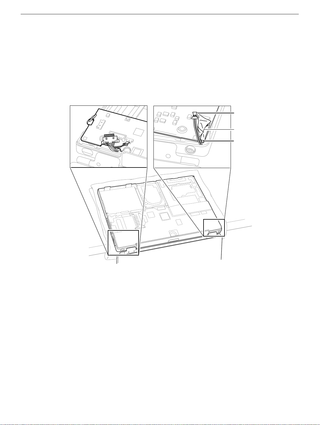
8. At the right side of the board, as shown, disconnect
• PMU connector
• DVD drive connector
• Two-pin power connector
Note: If tape is covering the power connector and cable, carefully pull it out of the
way. Place the tape aside for reuse on the replacement logic board.
9. Verify that the EMI clip—located between the DVD drive connector and the PMU
connector— is loose and does not catch on the logic board.
EMI Clip
PMU Connector
DVD Drive Connector
Power Connector
PowerBook G4 Logic Board - 6
Page 67

10. Grasp the logic board near the AirPort Card carrier. Gently tilt up the board, being
careful where it catches on the back panel ports, integral mesh liner, and the
disconnected cables.
If necessary, open the panel door and press on the ports to free the logic board from
the back panel.
Note: When reassembling the computer, make sure the replacement logic
board ports align completely with the openings in the back panel.
PowerBook G4 Logic Board - 7
Page 68
Note: When positioning the replacement logic board into the computer, check
that cables and connectors do not get caught under the board. Tilt the logic
board toward the back panel, and place the following cables into the notches in
the board:
• Power cable (reapply tape over the power cable, if applicable)
• Backlight cable
• LVDS cable
• Audio cable
Power
Connector
Tape
Notch
11. Remove existing memory cards from the logic board for installation on the
replacement logic board.
12. Disconnect the small infrared communications board at J1 for installation on the
replacement logic board.
13. Make sure the replacement logic board includes the following items. If not, transfer
these items from the original logic board to the replacement board:
• AirPort Card carrier
• Spongy mesh “pillows” adhered to USB ports and headphones port
• Kapton tape at underside of LVDS connector and on top of power connector
• Rubber adhesive squares at components L7 and L8, and on the monitor port and
the modem port
• Two adhesive rubber squares on underside of board at left side
• RJ-11 port. Note: If the replacement logic board has a metallic EMI cage around
the RJ-11 slot but does not include the port, transfer the RJ-11 port from the bad
board only if it does not have a ferrite bead around the wires. If it does, you must
order the RJ-11 port that does not have a ferrite bead (part number 922-5245).
PowerBook G4 Logic Board - 8
Page 69

14. Check that the heat exchanger has two square thermal interface pads in place. If the
pads are missing or damaged, replace them.
15. Important: If you have removed the logic board to access another part, and you will
be placing the original logic board back in the computer, use a razor blade to gently
scrape away any residual thermal transfer material from the heat exchanger and the
microprocessor chip.
Warning: When scraping away the thermal transfer material from the
microprocessor chip, be careful not to nick the microprocessor chip.
Apply new thermal transfer material to the microprocessor chip as described in the
next step.
Thermal
Transfer
Material
Razor
Blade
PowerBook G4 Logic Board - 9
Page 70

16. On the replacement logic board, center new thermal transfer material over the epoxy
cap on the microprocessor chip. Press it into place.
Thermal Transfer Material
17. Install the replacement logic board, and reassemble and test the computer.
PowerBook G4 Logic Board - 10
Page 71

PowerBook G4
Display Module
Replacement Instructions
The following instructions explain how to replace the display module on the PowerBook G4
computer.
Warning: Make sure you carefully follow these instructions, especially when
working near cables that attach to the replacement display module. If any of the
cables are damaged, the entire display module must be replaced.
Tools
• Soft cloth
• Torx T8 screwdriver
• #1 Phillips screwdriver
• Black stick (or other nonconductive nylon or plastic tool)
Note: To organize the screws you remove from the computer, use a tray with divided
compartments (such as a plastic ice cube tray).
Preliminary Steps
Before you begin, remove the following:
• Battery
• Keyboard
• Modem
• Bottom case
• AirPort Card (if installed)
• Logic board
© 2003 Apple Computer, Inc. All rights reserved.
Page 72

Procedure
Important: With the bottom case removed, be careful when turning over the computer.
Some components could become loose and fall out.
1. Open the computer to an approximate 45-degree angle, and stand it on a soft cloth
with the clutch covers facing up.
2. Remove the four identical Torx T8 screws from the clutch covers (two screws on each
clutch cover).
PowerBook G4 Display Module - 2
Page 73

3. Close the computer, and use a black stick to pry off the two clutch covers.
Important: When reassembling the computer, note that each clutch cover has a
molded number centered inside it. When the computer is positioned upside down, as
shown below, the left clutch cover is labeled "1"; the right clutch cover is labeled "2".
Make sure the left and right clutch covers are placed correctly on the clutches.
PowerBook G4 Display Module - 3
Page 74

4. Warning: Be especially careful when working near cables that attach to the
display. If any of these cables are damaged, the entire display module must be
replaced.
Warning: At the left clutch, the wrapped cable connected to the LVDS (low
voltage data signal) connector is extremely delicate. Do not pull or pinch the
LVDS cable. Do not allow the screwdriver to touch the LVDS cable.
Use a black stick to gently move aside the LVDS cable so you can access the two
silver-colored screws. (Do not remove the black screws beneath them.)
Remove the two silver-colored Phillips screws from the left clutch. Notice that the
screw closest to the LVDS cable has a sloped screw head.
Important: When installing a replacement display, make sure the screw closest to
the LVDS cable is the screw with the sloped head.
PowerBook G4 Display Module - 4
Page 75

5. At the right clutch, note the routing of the inverter cable (the black and pink wires).
Without straining the inverter cable, gently move it aside so you can access the two
silver-colored screws.
6. Remove the two identical silver-colored Phillips screws from the right clutch. (Do not
remove the black screws.)
7. Remove the Kapton tape, and reserve it for the replacement display module.
8. Disconnect the inverter cable, and lift the inner clutch mount out of the way.
9. Lift the top case up slightly from the display, and carefully slide the inverter cable out
through the hole in the top case.
PowerBook G4 Display Module - 5
Page 76

10. Warning: The LVDS cable and connector are extremely delicate. Do not pull or
pinch the LVDS cable or connector.
On the left side, move the inner clutch mount out of the way, and thread the blueand-white power switch cable through the opening in the top case.
11. Warning: The LVDS cable and connector are extremely delicate. Do not pull or
pinch the LVDS cable or connector.
Carefully guide the LVDS cable through the hole by turning the LVDS connector
sideways, as shown, to fit through the opening.
PowerBook G4 Display Module - 6
Page 77

12. If necessary, press the computer latch on the front of the computer to release
the display module from the top case.
13 . The display module includes all three cables.
14. Install the replacement display module, and reassemble and test the computer.
Important: When the replacement display module is installed, and before the
clutch covers are installed, test that the display is seated properly. With the
computer upright and closed, press the computer latch. The display module
should pop up slightly if the module is properly seated.
PowerBook G4 Display Module - 7
Page 78

PowerBook G4
PC Card Cage
Replacement Instructions
The following instructions explain how to replace the PC card cage in the PowerBook G4
computer.
Tools
• Soft towel or cloth larger than the PowerBook
• Torx T8 screwdriver
Note: To organize the screws you remove from the computer, use a tray with divided
compartments (such as a plastic ice cube tray).
Preliminary Steps
Before you begin, remove the following:
• Battery
• Keyboard
• Modem
• Bottom case
• AirPort Card (if installed)
• Logic board
© 2003 Apple Computer, Inc. All rights reserved.
Page 79

Procedure
1. To protect the display from scratches, place a sheet of paper between the display face
and the top case. (Make sure the paper does not block the computer latch.) With the
computer on a soft cloth, remove the two screws that attach the PC card cage to the
rib frame. (The longer screw is next to the battery connector.)
2. Lift out the PC card cage, being careful where it can catch on the PC card eject button.
3. Install the replacement PC card cage, and reassemble and test the computer.
PowerBook G4 PC Card Carrier - 2
Page 80

PowerBook G4
Rib Frame and Heat Exchanger
Replacement Instructions
The following instructions explain how to replace the rib frame and the heat exchanger in
the PowerBook G4 computer.
Tools
• Soft towel or cloth larger than the PowerBook
• Torx T8 screwdriver
• Torx T6 screwdriver
Note: To organize the screws you remove from the computer, use a tray with divided
compartments (such as a plastic ice cube tray).
Preliminary Steps
Before you begin, remove the following:
• Battery
• Keyboard
• Modem
• Bottom case
• AirPort Card (if installed)
• Hard drive
• DVD-ROM drive
• Logic board
• PC card cage
© 2003 Apple Computer, Inc. All rights reserved.
Page 81

Procedure
1. With the computer on a soft cloth, remove the four identical screws from the top case.
2. To protect the display from scratches, place a sheet of paper between the display face
and the top case. (Make sure the paper does not block the computer latch.) Close the
computer
3. Open the I/O door, and remove the four identical Torx T6 screws.
4. Turn over the computer, and remove the four identical black screws.
Note: You might need to move aside the AirPort antenna cable to reach one of the
screws.
PowerBook G4 Rib Frame and Heat Exchanger - 2
Page 82

5. Warning: When removing the rib frame and heat exchanger, make sure the heat
exchanger does not fall onto the display. Support both the rib frame and the heat
exchanger as you lift them out.
Note: The heat exchanger is loosely attached to the rib frame at two slots. Notice
that the heat exchanger fits under the rib frame on the left, and over the rib frame on
the right, as shown below.
.
PowerBook G4 Rib Frame and Heat Exchanger - 3
Page 83

6. Install the replacement rib frame and/or heat exchanger, and reassemble and test the
computer.
Note: The replacement rib frame includes the following:
• Back panel mounts (two)
• EMI clip
• Battery latch mechanism
• Battery connector
• EMI strip (serrated edge)
PowerBook G4 Rib Frame and Heat Exchanger - 4
Page 84

PowerBook G4
Inverter Board
Replacement Instructions
The following instructions explain how to replace the inverter board in the PowerBook G4
computer.
Tools
• Soft towel or cloth larger than the PowerBook
• Torx T8 screwdriver
• #1 Phillips screwdriver
• Black stick (or other nonconductive plastic or nylon tool)
Note: To organize the screws you remove from the computer, use a tray with divided
compartments (such as a plastic ice cube tray).
Preliminary Steps
Before you begin, remove the following:
• Battery
• Keyboard
• Modem
• Bottom case
• AirPort Card (if installed)
• Hard drive
• DVD-ROM drive
• Logic board
• Rib frame
© 2003 Apple Computer, Inc. All rights reserved.
Page 85

Procedure
1. With the computer on a soft cloth, remove the two identical screws from the clutch
cover that is next to the power adapter port, as shown.
2. Use a black stick to remove the clutch cover.
3. At the clutch, note the routing of the inverter cable (the black and pink wires). Without
straining the inverter cable, gently remove the Kapton tape from the inverter cable.
Disconnect the inverter cable from the inverter board.
4. Remove the two identical silver-colored Phillips screws from the right clutch. (Do not
remove the black screws.)
PowerBook G4 Inverter Board - 2
Page 86

5. Lift the inner clutch mount out of the way.
6. Tilt up the inverter board, and disconnect the PMU cable. Lift out the inverter board.
7. Install the replacement inverter board, and reassemble and test the computer.
PowerBook G4 Inverter Board - 3
Page 87

PowerBook G4
Top Case
Replacement Instructions
The following instructions explain how to replace the top case in the PowerBook G4
computer.
Tools
• Soft towel or cloth larger than the PowerBook
• Black stick (or other nonconductive plastic or nylon tool)
Preliminary Steps
Before you begin, remove the following:
• Battery
• Keyboard
• Modem
• AirPort Card (if installed)
• Bottom case
• Hard drive
• DVD-ROM drive
• PMU card
• Backup battery
• Logic board
• Rib frame and heat exchanger
• Inverter board
• Display module
© 2003 Apple Computer, Inc. All rights reserved.
Page 88

Procedure
1. With the top case on a soft cloth, notice the placement of the transparent, orange
Kapton tape and the routing of the PMU ribbon cable.
PMU Ribbon Cable
2. Use a black stick to peel off the Kapton tape from the PMU ribbon cable. Reserve the
ribbon cable for the replacement top case.
Kapton Tape
PowerBook G4 Top Case - 2
Page 89

3. Before installing the replacement top case, make sure it includes the following:
• Fan (heatstaked to top case)
• Speaker set and cables
• Door at back panel
• Mesh liner at ports
• Inner clutch mounts (two)
• Power button and board (heatstaked to top case)
• AirPort antenna cable
• Trackpad assembly with board and cable
4. Important: Make sure you transfer the original serial number label from the old top
case to the serial number panel on the replacement top case. You can use a black
stick to carefully peel up a corner of the label. Then peel off the label completely and
apply it to the serial number panel. Make sure that the label lies completely flat so it
does not interfere with the battery compartment.
Power Button
AirPort
Antenna Cable
Fan
Trackpad
Clutch Mount
DoorLiner
Speaker
Serial Number Panel
5. Install the replacement top case, and reassemble and test the computer.
PowerBook G4 Top Case - 3
Page 90

PowerBook G4 Screw Reference Sheet
This sheet shows the types of screws used in the PowerBook G4
computer. To see where the screws are located in the computer,
refer to "PowerBook G4 Screw Locator."
Modem, magnetic 1 @ 7 mm
Bottom Case 8 @ 8 mm
Hard Drive 4 @ 5 mm (black)
Logic Board 3 @ 4.5 mm
Logic Board 1 @ 4.5 mm
Logic Board 2 @ 8 mm
PC Card Cage 1 @ 6.5 mm
PC Card Cage 1 @ 4.5 mm
Rib Frame 4 @ 4.5 mm
Rib Frame, Clutch, 4 @ 5.25 mm
Rib Frame, Clutch, 3 @ 16.5 mm
Rib Frame, Clutch, 1 @ 16.5 mm
Rib Frame, Back 4 @ 4.5 mm
Rib Frame 4 @ 9.5 mm (black)
© 2003 Apple Computer, Inc. All rights reserved.
Page 91

PowerBook G4 Screw Locator - 1 of 4
Modem Replacement
One 5 mm magnetic hex nut,
7 mm long
Bottom Case Replacement
Eight identical Phillips,
8 mm long
Hard Drive Replacement
Four identical (black) Torx T8,
5 mm long
© 2003 Apple Computer, Inc. All rights reserved.
Page 92

PowerBook G4 Screw Locator - 2 of 4
Logic Board Replacement
(A) - Two identical Torx T8,
4.5 mm long
(B) - One Torx T8,
4.5 mm long
Two identical Torx T8,
8 mm long
B
A
A
PC Card Replacement
(C) - One Torx T8,
4.5 mm long
(D) - One Torx T8,
6.5 mm long
C
D
Page 93

PowerBook G4 Screw Locator - 3 of 4
Rib Frame and Heat Exchanger Replacement
Four identical Torx T8,
4.5 mm long
Four identical Torx T8,
5.25 mm long
(E) - One Phillips,
16.5 mm long
(F) - One Phillips,
16.5 mm long
Two identical Phillips,
16.5 mm long
E
F
Page 94

PowerBook G4 Screw Locator - 4 of 4
Four identical Torx T6,
4.5 mm long
Four identical
(Black) Torx T8,
9.5 mm long
Page 95

Service Source
Troubleshooting
PowerBook G4
© 2003 Apple Computer, Inc. All rights reserved.
Page 96

TITLE
PowerBook G4: Troubleshooting Document
Writer:
Created:
Modified:
Huckabone, Michael
2001-7-20
2001-7-20
TOPIC
This is a PDF document of recent troubleshooting articles for Apple Specialists,
Apple-Authorized Self-Servicing Providers and Internal Use.
DISCUSSION
AirPort
AirPort Card Not Recognized
Battery
Battery Will Not Eject
Hard drive
Hard Drive Will Not Initialize
Modem
No Modem Dial Tone
Optical drive
DVD Disc Icon Does Not Show Up On Desktop, Or A Dialog Box Appears To Initialize Disc
PC Card
PC Card Will Not Insert
Sound
No Sound And Sound Control Panel Indicates An External Device Is Plugged In
Video
No Display, Or Dim Display, But Computer Appears To Operate Correctly
No Video On External Device Connected Via S-Video Port
No Video On External Device Connected To External Monitor Port
Misc. symptoms
Latch Not Working
Date And Time Resets All The Time
-3278 Error
Microphone Not Working
Page 97

Beeps Are Heard at Startup (one to four beeps)
Dialog Box "Built-in Memory Test Has Detected an Error" Comes Up On Startup
When displaying a single color over the screen area, the LCD panel shows
one or more pixels that are not properly lit
Display
Page 98

TITLE
PowerBook G4: AirPort Card Not Recognized
Writer:
Created:
Modified:
Huckabone, Michael
2001-7-20
2001-8-17
TOPIC
AirPort Card not recognized.
DISCUSSION
*RESTRICTED: Apple Specialists/Apple-Authorized Self-Servicing Providers *
Internal Use Only
Troubleshooting Procedure
The steps to solve a symptom are listed sequentially. You might not need to perform every step
before the symptom is solved. Start with the first step, and then test for the symptom. If the
symptom persists, replace any modules you removed, go to the next step, and test again.
Continue down the list until the symptom is solved.
Use Software Update control panel or see the Apple Software Updates web page to make
sure the latest version of AirPort software is installed.
1.
Boot using Mac OS All extensions setting.2.
Reseat AirPort Card.3.
Remove and reinstall the AirPort software.4.
Replace with known-good AirPort Card.5.
Replace logic board.6.
Document Information
Product Area: PowerBook G4
Category: PowerBook G4 Hardware
Sub Category: Troubleshooting
Keywords: kpbook kssts hts
Contributor:
Process Owner:
Page 99

Support Site Index | Export Compliance
Contact Us | Privacy Notice
Copyright © 2001 Apple Computer, Inc. All rights reserved.
1-800-MY-APPLE
Page 100

TITLE
PowerBook G4: Battery Will Not Eject
Writer:
Created:
Modified:
Huckabone, Michael
2001-7-20
2001-8-17
TOPIC
Releasing the battery latch does not eject the battery.
DISCUSSION
*RESTRICTED: Apple Specialists/Apple-Authorized Self-Servicing Providers *
Internal Use Only
Troubleshooting Procedure
The steps to solve a symptom are listed sequentially. You might not need to perform every step
before the symptom is solved. Start with the first step, and then test for the symptom. If the
symptom persists, replace any modules you removed, go to the next step, and test again.
Continue down the list until the symptom is solved.
Flip over the unit and release the battery latch by sliding the latch towards the PC Card
button.
1.
If the battery still will not eject, while holding the latch towards the PC Card button, use a
small plastic flat-blade tool to pry the battery around the battery latch.
2.
Verify proper latch operation, by exercixing the latch. If it does not move smoothly or
evenly, replace rib chassis assembly.
3.
If the latch does exercise correctly, verify that the customer is not installing the battery
with excessive force.
4.
Document Information
Product Area: PowerBook G4
Category: PowerBook G4 Hardware
Sub Category: Troubleshooting
Keywords: kpbook kssts hts
Contributor:
Process Owner:
 Loading...