

Page 1
Service Source
MacBook (13-inch)
MacBook (13-inch)
MacBook (13-inch Late 2006)
MacBook (13-inch Mid 2007)
Updated: 2010-06-07
© 2007, 2008 Apple Inc. All rights reserved.
Page 2

Apple Inc.
© 2007, 2008 Apple Inc. All rights reserved.
Under the copyright laws, this document may not be copied, in whole or in part, without the
written consent of Apple.
Every eort has been made to ensure that the information in this document is accurate. Apple is
not responsible for printing or clerical errors.
Apple
1 Innite Loop
Cupertino, CA 95014-2084
USA
+ 1 408 996 1010
www.apple.com
Apple, the Apple logo, Mac, and MacBook are trademarks of Apple Inc., registered in the U.S. and
other countries.
ii
Page 3

MacBook (13-inch)
Contents
Take Apart
Manual Updates 9
Updated 07 June 2010 9
Updated 28 April 2010 9
Updated 24 July 2009 9
Updated 25 April 2008 9
Updated 2 April 2008 9
General Information 10
What’s New 10
Product Congurations 11
Vertical-Insert Connectors 13
Tools 13
Power Adapter 14
Temperature Concerns 14
Note About Images in This Manual 14
Logic Board Springs 15
Simplied Flowchart for Take Apart 16
Battery 17
RAM Door (L-Bracket) 20
Memory (DIMMs) 24
Removal Procedure 25
Replacement Procedure 26
Removing a Stuck Memory Card 28
Hard Drive 29
Top Case (with Keyboard) 33
Top Case/Display Bezel Kit: White Only 46
New Kit Available in June 2010 46
Before Ordering Parts 46
Note About International Parts 46
Trackpad Cable (Late 2006 Model Only) 47
AirPort Extreme Card 52
Page 4

MagSafe DC-In Board 57
Left Speaker 61
Battery Connector with Sleep Switch 65
Hard Drive Connector 72
Fan 78
Heatsink 81
Checking the Thermal Grease 85
Comparing Heatsinks 91
Bluetooth Holder 92
Optical Drive 96
Handling Slot-Load Optical Drives 106
Removing a Stuck Disc from an Optical Drive 110
Optical Drive Cable 112
I/O Frame (with upper EMI shield) 116
Logic Board 120
DIMM Lever Kit 131
Backup Battery 135
Bluetooth Antenna Board and Cable 138
Bluetooth Board 142
Bluetooth-to-Logic Board Cable 146
Subwoofer with Right Speaker Cable 151
Midframe 157
Display Bezel 162
Removal Procedure 163
Replacement Procedure 166
Bezel Mounting Clips 169
Removal Procedure 170
Replacement Procedure 171
Spacers at Bezel Scoops 173
C-Channel 175
Page 5

Clutch Block, Left 179
Clutch Block, Right 186
Clutch Caps 190
(Refer to “Clutch Block, Left” and “Clutch Block, Right”) 190
Display Module 191
Bottom Case 198
Clutch Cover 202
Bezel Scoops, Left and Right 208
LCD Panel 212
Antenna Receptors and Cables, Top and Left 218
Antenna Receptor and Cable, Right (Late 2006 Model Only) 223
LCD Panel Assembly 231
Removal Procedure 233
Reinstallation Procedure 238
Foil at Camera Bracket (Original MacBook Model) 246
Spacers at Camera Bracket 249
Camera Assembly 251
LVDS Cable with USB Line 257
Microphone Cable 264
Inverter Board 271
Inverter Cable 274
Display Hinges, Left and Right 277
Bezel Brace, Left 280
Bezel Brace, Right 282
Sleep Magnet 286
Display Magnet Pairs 289
Display Rear Housing 293
Page 6

Additional Procedures
General Information 297
Replacing Darfon Keycaps 298
Preliminary Steps 298
Part Location 298
Procedure 298
Replacing Mitsumi Keycaps 313
Preliminary Steps 313
Part Location 313
Procedure 314
Troubleshooting
General Information 329
Troubleshooting Steps 330
Symptom Charts 333
Block Diagram 344
Views
External and Internal Views 347
Front: Keyboard and IR Window 347
Back: Air Vents and Display Clutch 348
Left Side: Ports 348
Right Side: Slot Drive 348
Battery Bay: Memory Card Levers and Hard Drive Pull Tab 349
Top Case Removed: Main Modules and Cable Routing 349
Screw Charts 355
Top Case Screw Locations 355
Display Module Screw Locations 356
Logic Board Screw Locations 357
LCD Panel Screw Locations 358
Screw Reference Chart, Part 1 of 3 359
Screw Reference Chart, Part 2 of 3 360
Screw Reference Chart, Part 3 of 3 361
Exploded Views 362
MacBook (13-inch)—Display Exploded View 362
MacBook (13-inch)—Main Exploded View 363
MacBook (13-inch Late 2006)—Display Exploded View 364
Page 7

MacBook (13-inch Late 2006)—Main Exploded View 365
MacBook (13-inch Mid 2007)—Display Exploded View 366
MacBook (13-inch Mid 2007)—Main Exploded View 367
Page 8

Service Source
Take Apart
MacBook (13-inch)
© 2006, 2007 Apple Inc. All rights reserved.
Page 9

Manual Updates
Updated 07 June 2010
Take Apart:
• Top Case/Display Bezel Kit: White Only: Added new topic describing how to order a kit
containing a white top case and a white display bezel for MacBook (13-inch Late 2006) and
MacBook (13-inch Mid 2007) models
Views:
• Exploded Views: Updated top case and display bezel part numbers for MacBook (13-inch Late
2006) and MacBook (13-inch Mid 2007) models
Updated 28 April 2010
Take Apart:
• Hard Drive: Added note about placement of shoulder screws
Updated 24 July 2009
Take Apart:
• Top Case: Added Replacement Warning and image to show placement of shims near hard
drive to prevent top case cracks
Updated 25 April 2008
Troubleshooting:
• Revised battery symptoms
• Added display symptom
Updated 2 April 2008
Troubleshooting
• Symptom Charts: Computer shuts down intermittently: Revised step 5 to more closely follow
a Knowledge Base article.
Manual introduced 16 May 2006
MacBook (13-inch) Take Apart — Manual Updates 9
Page 10
General Information
What’s New
The MacBook (13-inch) portable computer is the rst computer of its size featuring the Intel Core
Duo processor and built-in iSight video camera. The main features and service dierences (from
similar-sized Apple portable computers) include:
• Higher resolution 13.3-inch LCD panel
• iSight camera built-in
• Infrared sensor on front right corner
• Hard drive is oered as a customer-replaceable module
• Digital audio-in
• MagSafe magnetic power connector
• Supports extended desktop
• Vertical-insert connectors—most of the cable connectors on the logic board use a new
design that requires special insertion and extraction (refer to the section “Vertical-Insert
Connectors” in this chapter)
• Feet on the bottom case are heat-staked, so they are not removable
MacBook (13-inch) Take Apart — General Information 10
Page 11
• Built-in keyboard as part of top case
• Operating temperature is hotter than previous models (refer to “Temperature Concerns” in
this chapter)
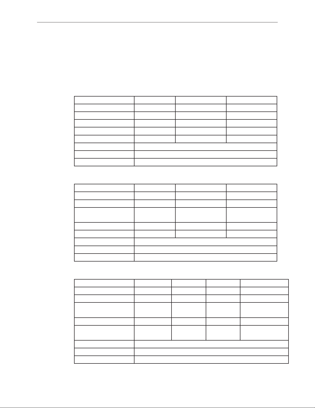
Product Congurations
The following table shows the MacBook (13-inch) model congurations at introduction:
Feature Good Better Best
Intel Core Duo processor 1.83 GHz 2.0 GHz 2.0 GHz
Memory 512 MB (x2) 512 MB (x2) 512 MB (x2)
Hard Drive 60 GB 60 GB 80 GB (120 GB)
Optical Drive Combo, 9.5 mm Super, 9.5 mm Super, 9.5 mm
Housing White White Black
Display 13.3-inch, 1280x800, 114 dpi, Low Reection Glossy Polarizer (LRGP)
Battery 55-Whr Lithium Polymer
Power Adapter 60 W, A70, MagSafe MPM
The following table shows the MacBook (13-inch Late 2006) model congurations at introduction:
Feature Good Better Best
Intel Core 2 Duo processor 1.83 GHz 2.0 GHz 2.0 GHz
Memory 512 MB (x2) 1 GB (x2) 1 GB (x2)
Hard Drive 60 GB 80 GB 120 GB, (160 GB, 200
GB)
Optical Drive Combo, 9.5 mm Super, 9.5 mm Super, 9.5 mm
Housing White White Black
Display 13.3-inch, 1280x800, 114 dpi, Low Reection Glossy Polarizer (LRGP)
Battery 55-Whr Lithium Polymer
Power Adapter 60 W, A77, MagSafe MPM
The following table shows the MacBook (13-inch Mid 2007) model congurations at introduction:
Feature Good Better Best Ultimate
Intel Core 2 Duo processor 2.0 GHz 2.16 GHz 2.16 GHz 2.16 GHz
Memory 512 MB (x2) 512 MB (x2) 512 MB (x2) 1 GB (x2)
Hard Drive 80 GB 120 GB 160 GB 120 GB (Better) or
160 GB, 200 GB (Best)
Optical Drive Combo, 9.5 mm Super, 9.5 mm Super, 9.5 mm Super, 9.5 mm
Housing White White Black White (Better) or
Black (Best)
Display 13.3-inch, 1280x800, 114 dpi, Low Reection Glossy Polarizer (LRGP)
Battery 55-Whr Lithium Polymer
Power Adapter 60 W, A77, MagSafe MPM
MacBook (13-inch) Take Apart — General Information 11
Page 12
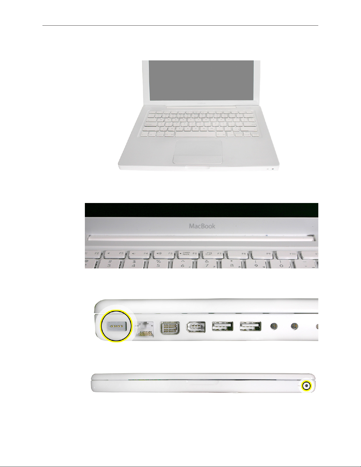
Keyboard integral to top case:
Product name on display bezel:
MagSafe power connector port:
Infrared window on front of computer:
For additional views of the computer, refer to the “Views” chapter at the end of this manual.
MacBook (13-inch) Take Apart — General Information 12
Page 13
Vertical-Insert Connectors
Most of the cable connectors on the logic board use a new design that requires special insertion
and extraction. Caution: To prevent damage to the connectors, install them from the front (away
from the cable) when reconnecting vertical-insert cables to the logic board.
Tools
Caution: To prevent scratches or other cosmetic damage to the computer housing, use a soft
cloth as a protective layer when removing and installing the external screws.
The tools required to service this computer include:
• Clean, soft, lint-free cloth
• Coin
• ESD wrist strap and mat
• Magnetic Phillips #0 screwdriver
• Magnetic Phillips #00 screwdriver (preferably with a long handle)
• Black stick (Apple probe tool, part number 922-5065) or other nonconductive nylon or plastic
atblade tool
• Access card (Apple part number 922-7172) to open the top case
• Jeweler’s atblade screwdriver
• Needlenose pliers
• Stack of books, weighted boxes, or other means of support for display while removing
screws from hinge
• Thermal grease (Apple thermal compound syringe, part number 922-7144)
• Alcohol wipes
• Permanent marking, felt-tip pen
• Standard size CD or DVD disc
• Flashlight or bright lamp
MacBook (13-inch) Take Apart — General Information 13
Page 14
Power Adapter
Warning: The power adapter for this computer is unique to this model. It uses an MPM 4-pin
adapter plug. Do not use this power adapter with any other portable computer. Power adapters
from earlier iBook or PowerBook computers are not compatible and will not t the MPM plug.
Temperature Concerns
This computer runs hotter than previous models. However, the normal operating temperature
is well within national and international safety standards. Nevertheless, customers may be
concerned about the generated heat. To prevent an unneeded repair, you can compare a
customer’s computer to a running model, if available, at your repair site. For more information
on temperature concerns and customer perception, refer to Knowledge Base article 30612 “Apple
Notebooks: Operating Temperature.”
http://docs.info.apple.com/article.html?artnum=30612
Note About Images in This Manual
Because a pre-production model was used for most of the images shown in this manual, you may
notice small dierences in appearance between the image pictured and the computer you are
servicing. However, although the appearance diers, the steps and sequence are the same unless
noted.
Memory Card Levers
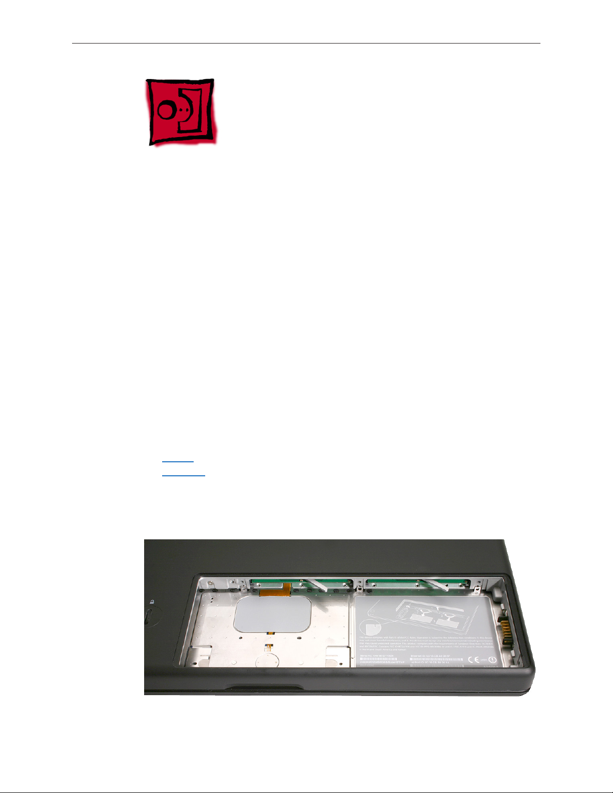
Important: The following image shows the memory cards and hard drive installed in the battery
bay. Note the correct position of the memory card levers. Some images pictured in this manual
used a pre-production model, so the direction and appearance of the levers dier from the
accurate depiction below. Refer to the Views chapter for other useful reference images.
MacBook (13-inch) Take Apart — General Information 14
Page 15
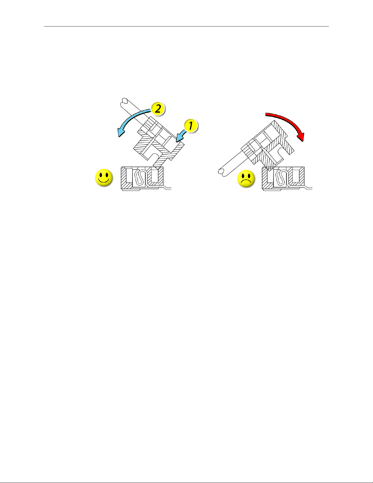
Logic Board Springs
Caution: When servicing the computer, be especially careful when working near the two springs
on the logic board. Although the springs are exible, they can be inadvertently torn, bent, or
broken if a cable gets caught on them. A logic board might be considered unusable with one or
more damaged springs. Check the structural integrity of the springs before completing a repair.
MacBook (13-inch) Take Apart — General Information 15
Page 16
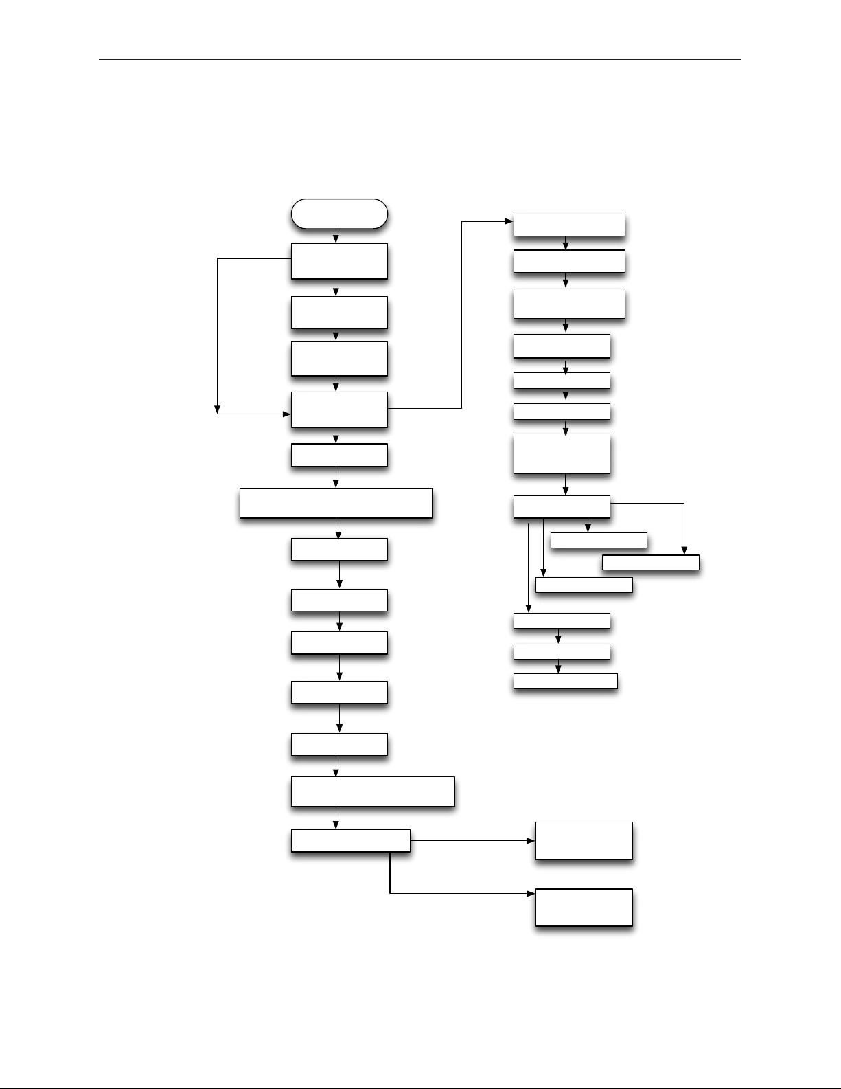
Simplied Flowchart for Take Apart
Although this owchart does not include every serviceable part, you can use it as a reference
after becoming familiar with the detailed removal procedures.
Remove
Battery
Remove MagSafe
DC-In Board
Remove RAM Door
(L-Bracket)
Remove Hard Drive
Remove RAM
(2 DIMMS)
Remove Top Case
with Keyboard
Remove ODD & C
Channel
Remove LCD Clutch Blocks: Left & Right
Remove Display
Module
Remove Display
Bezel
Remove Clutch Cvr
Remove Left Speaker
Remove AirPort
Extreme Card
Remove HDD Conn
Remove Fan
Remove Heatsink
Remove Batt Conn
(w/Sleep Switch)
Remove Optical
Drive & C-Channel
Remove Subwoofer
Remove R Speaker
Remove Midframe
Remove I/O frame
Remove Bluetooth
Remove Inverter
Remove L & R
Bezel Scoop
Disconnect LCD Panel Assembly
from Display Housing
Disconnect Bezel Braces
from LCD Panel
Remove Logic Board
Remove Antenna -
Inverter Cable
Assm.
Remove LVDSCam-Mic Cable
Assm.
MacBook (13-inch) Take Apart — General Information 16
Page 17
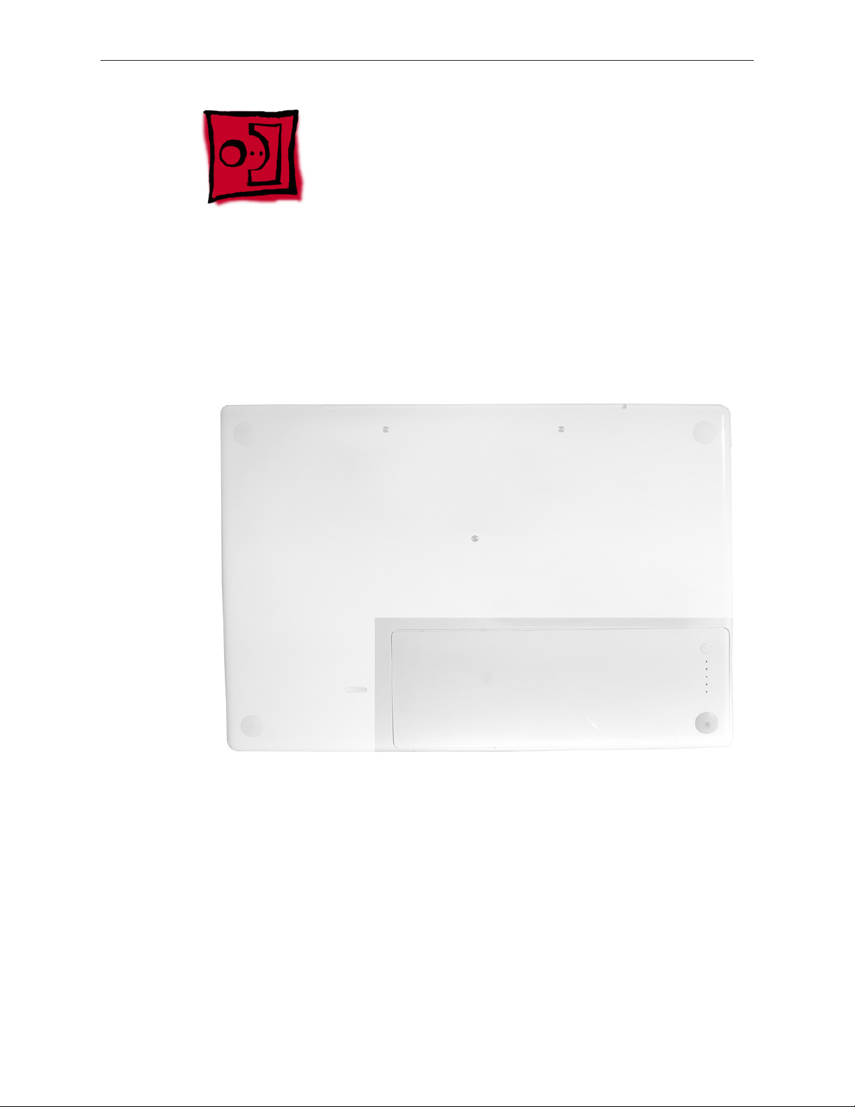
Battery
Tools
• Clean, soft, lint-free cloth
• Coin
Part Location
Preliminary Steps
Warning: Always shut down the computer before opening it to avoid damaging the internal
components or causing injury. After you shut down the computer, the internal components can
be very hot. Let the computer cool down for 30 minutes before continuing.
MacBook (13-inch) Take Apart — Battery 17
Page 18
Procedure
1. Shut down the computer.
2. Wait 30 minutes to allow the computer’s internal components to cool.
3. Unplug all external cables from the computer except the power cord.
4. Unplug the power cord.
5. Put on an ESD wrist strap.
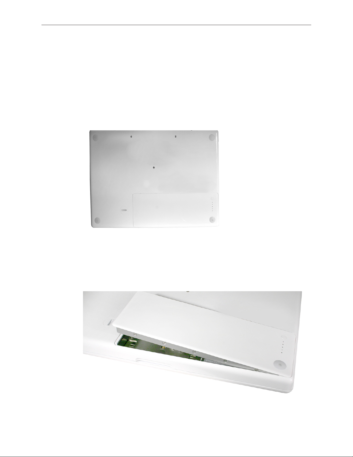
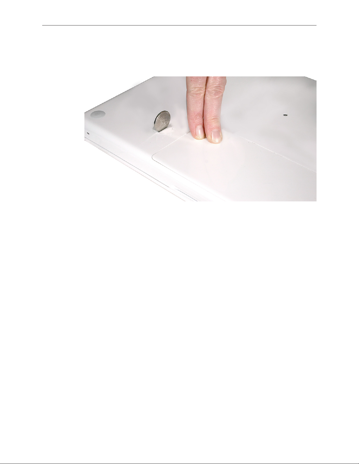
6. Turn over the computer and place it on a soft cloth.
7. Use a coin to release the battery latch. Turn the coin a quarter turn clockwise to unlock the
battery.
Caution: To prevent scratches or other cosmetic damage to the bottom case, use only a coin
to unlock and lock the battery.
8. Lift out the battery from the battery bay.
MacBook (13-inch) Take Apart — Battery 18
Page 19
9. To install the replacement battery, tilt the foot end of the battery into the battery bay rst.
Then press and hold down the other end of the battery as you turn the coin to lock it into
place.
10. Reassemble and test the computer.
MacBook (13-inch) Take Apart — Battery 19
Page 20
RAM Door (L-Bracket)
Tools
• Soft cloth
• ESD wrist strap and mat
• Magnetic Phillips #0 screwdriver
• Black stick (Apple part number 922-5065) or other nonconductive nylon or plastic atblade
tool
Preliminary Steps
Before you begin, remove the battery.
Part Location
MacBook (13-inch) Take Apart — RAM Door 20
Page 21
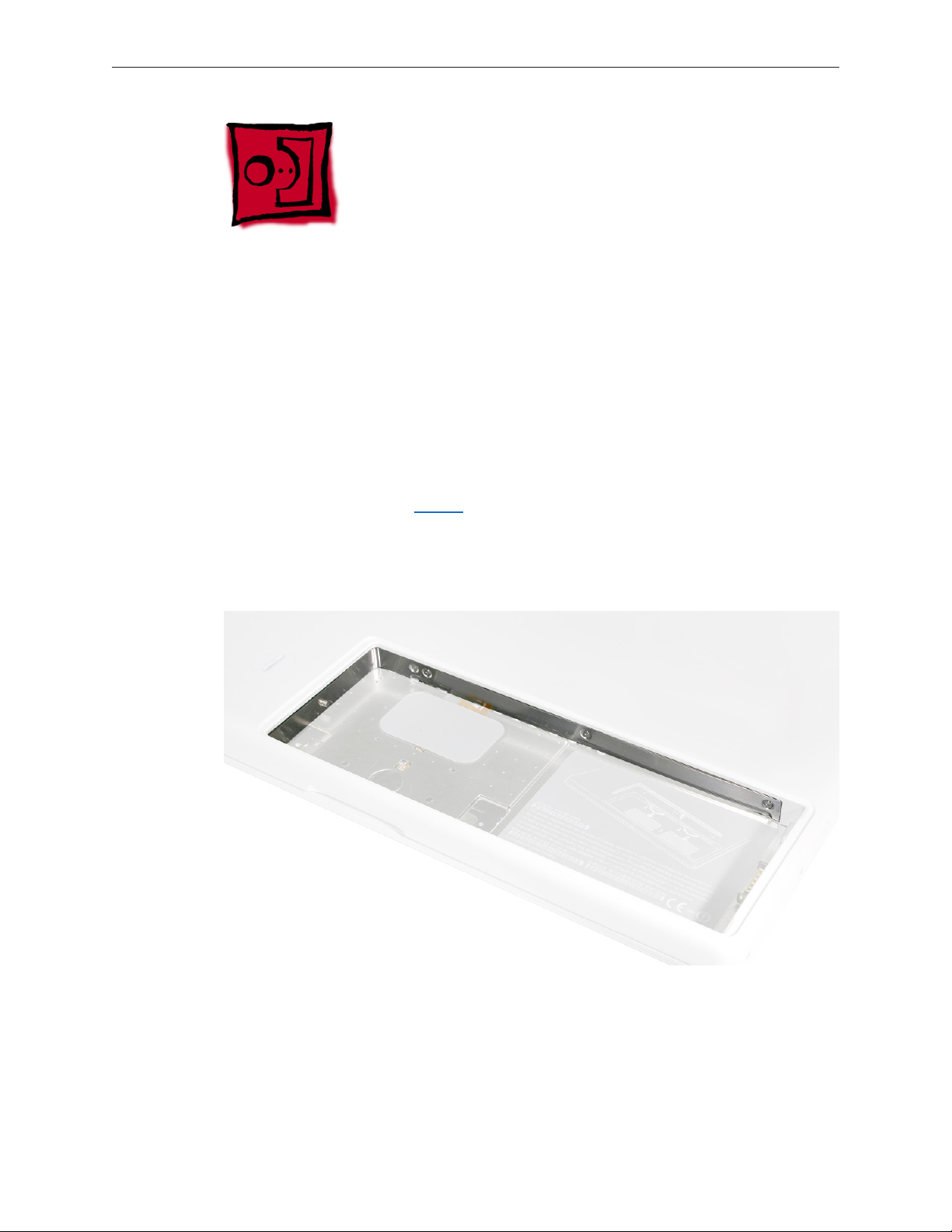
Procedure
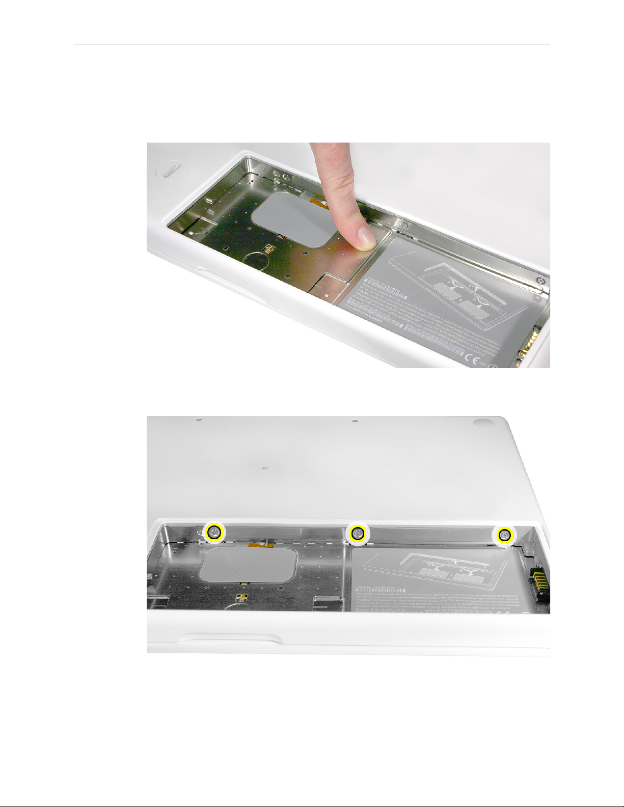
1. With the computer closed and upside down on a soft cloth, touch a metal surface inside the
battery bay to discharge any static electricity.
2. Loosen—but do not try to remove—the three captive screws along the RAM door.
MacBook (13-inch) Take Apart — RAM Door 21
Page 22
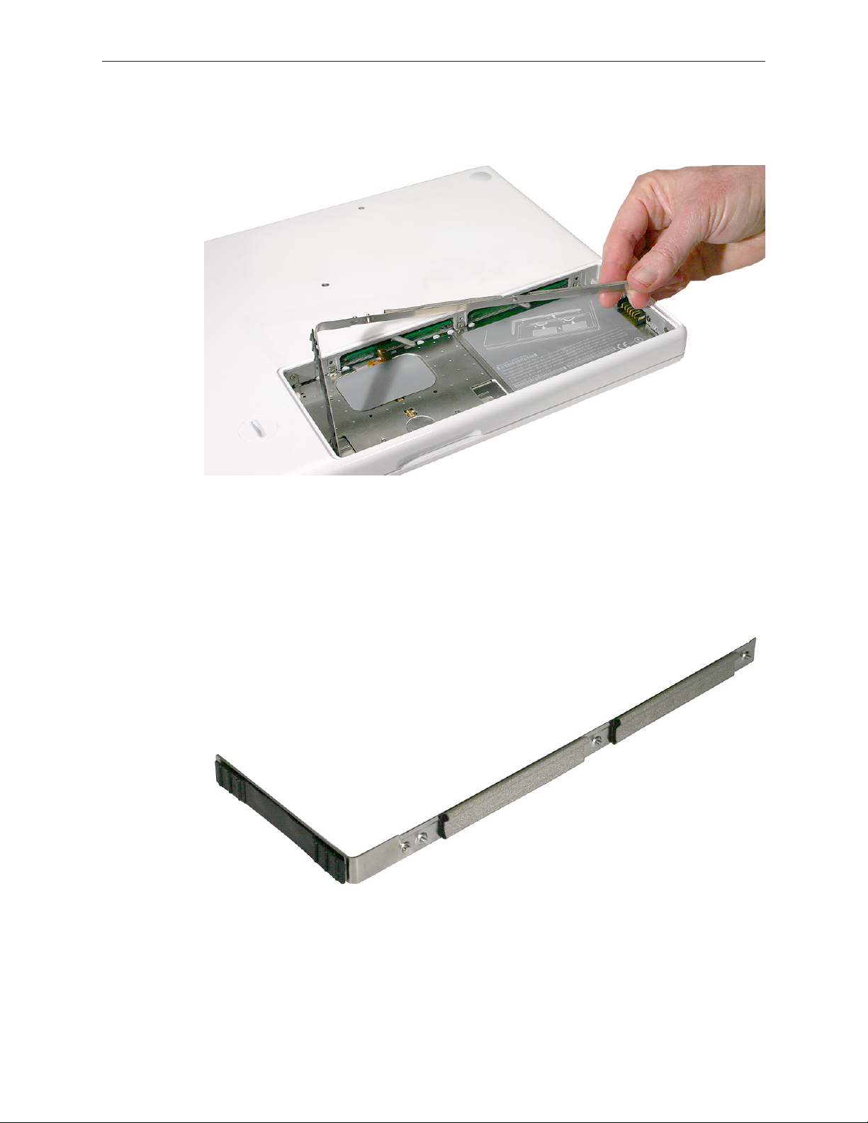
3. Holding the long end of the L-shaped RAM door, pivot it out from the battery bay. (If
necessary, use a black stick to tilt it up and out of the battery bay.) Be careful not to bend it.
Replacement Note: Before replacing the RAM door, make sure that
• Hard drive pull tab is not exposed
• Cards are fully inserted
• Memory card levers are fully down before replacing the RAM door
Replacement Note: Check that the replacement RAM door has a rubber cushion to protect
the hard drive opening and two EMI gaskets to protect the memory card openings.
MacBook (13-inch) Take Apart — RAM Door 22
Page 23
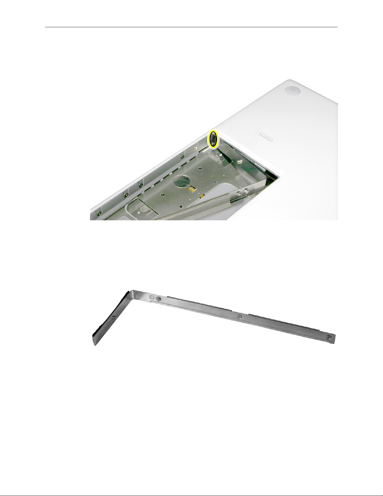
4. Replacement Note: Install the replacement RAM door by rst aligning the short end at the
notch near the hard drive opening.
Replacement Note: Use a black stick, if necessary, to tuck in the EMI gaskets so they do not
protrude from the edge of the battery bay. Make sure the three screws align with the holes
in the bottom case before tightening them.
5. Reassemble and test the computer.
MacBook (13-inch) Take Apart — RAM Door 23
Page 24
Memory (DIMMs)
This computer comes with a minimum of 512 MB of 667 GHz Double Data Rate 2 (DDR2)
Synchronous Dynamic Random-Access Memory (SDRAM) installed. It has two slots that can
accept SDRAM Small Outline Dual Inline Memory Modules (SO-DIMMs). The slots are side-by-side
on the logic board behind the RAM door. For best performance, memory should be installed
as pairs with an equal memory card in each slot. The maximum amount of memory for this
computer is 2 GB, with 1GB DIMM installed in each slot.
Memory cards must meet these requirements:
• 1.25 inch or smaller
• 256 MB, 512 MB, or 1 GB
• 200-pin
• PC-5300 DDR2 667 MHz Type RAM
Tools
• ESD wrist strap and mat
Preliminary Steps
Before you begin, remove
• Battery
• RAM door
Part Location
MacBook (13-inch) Take Apart — Memory 24
Page 25
Removal Procedure
1. Touch a metal surface inside the battery bay to discharge any static electricity.
2. Put on an ESD wrist strap.
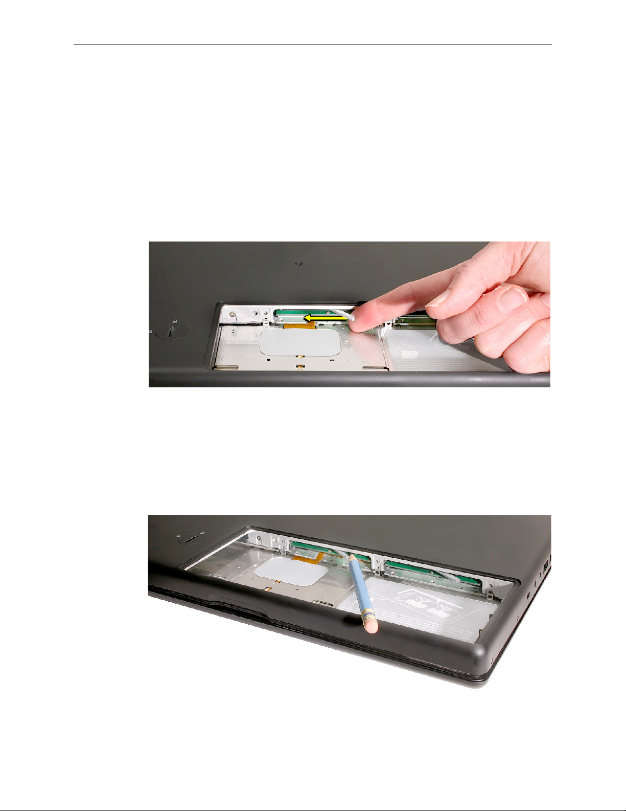
3. In one swift motion, use one nger to move the lever to the left and release it. This swift
motion ejects the memory card.
Caution: The memory card eject levers are on a spring hinge that operates on a side-to-side
horizontal plane. The mechanism can be damaged if the lever is forced outside of that
horizontal movement. To prevent damage to a lever, move it swiftly—in one sideways
direction only.
Note: Refer to the following if an issue occurs with a lever:
• If the lever wobbles, the lever may not be fully screwed in. Refer to “DIMM Lever Kit” in
this chapter.
• If the lever oers no resistance, the spring mechanism may be damaged. Refer to “DIMM
Lever Kit” in this chapter.
• If the lever is stuck in a completely closed position (recessed underneath the bottom
case), use a wooden pencil or black stick to gently pry it out, as shown below.
MacBook (13-inch) Take Apart — Memory 25
Page 26
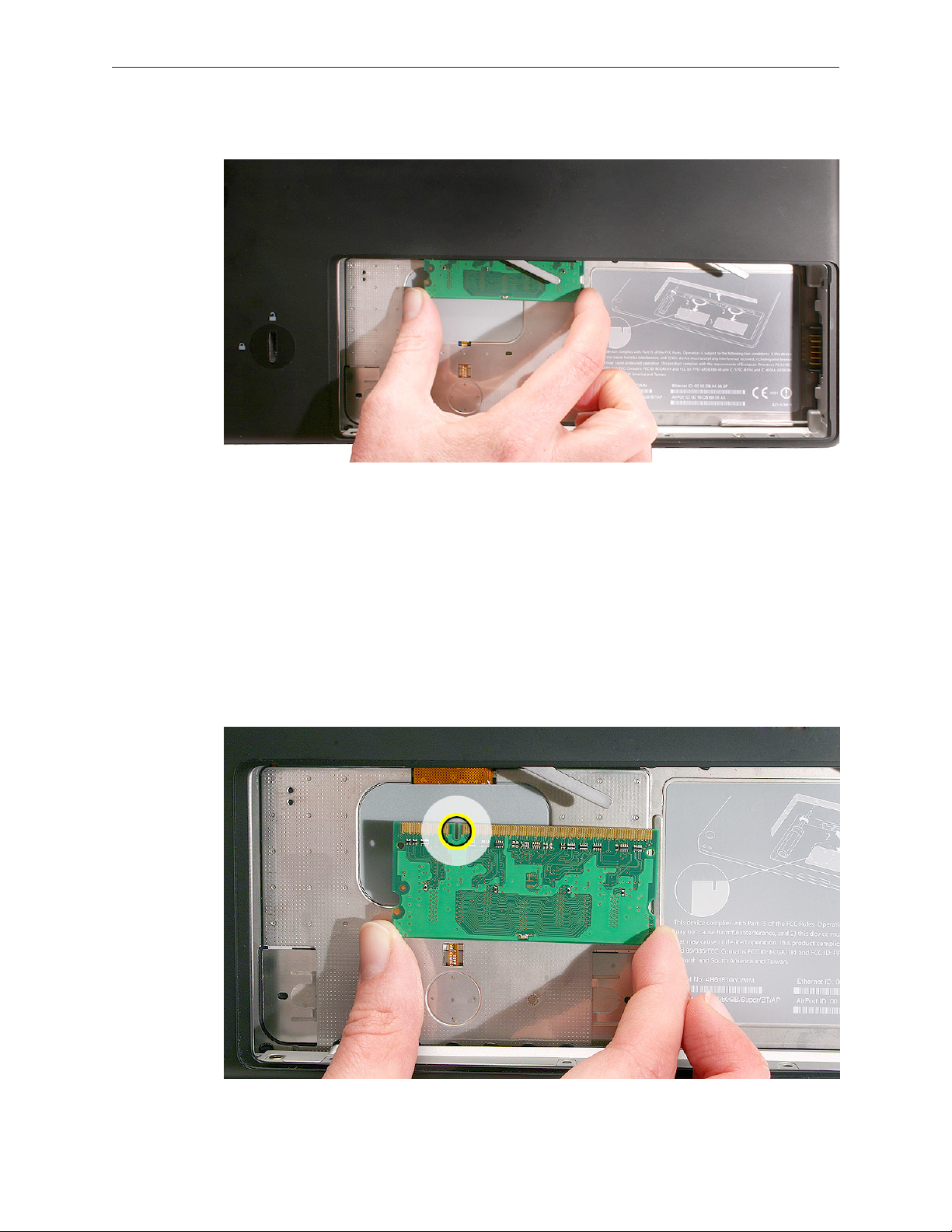
4. Holding the memory cards by the corners, slide them out from the battery bay.
Important: Do not touch the gold connectors. Handle the card only by its edges.
Note: A memory card might show a white residue when you remove it. This harmless
substance acts as a lubricant when installing the memory card at the factory, but it is not
required when reinstalling a memory card.
Replacement Procedure
1. Align the memory card so that the gold connectors face the slot and the notch is on the left.
(The chip side of the board faces down.)
MacBook (13-inch) Take Apart — Memory 26
Page 27
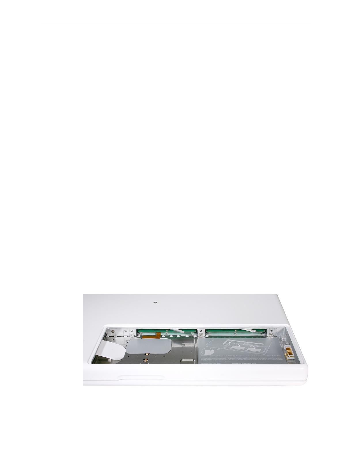
2. Use two ngers to push rmly on the edge of the memory cards. If there is a tight t,
installing the cards may take some force to ensure that they are fully inserted.
Important: When the cards are fully inserted, the edges of the cards are nearly hidden, as
shown by the recessed card on the right in the image below.
3. If the levers do not return to the closed position, move them to close them.
4. Reassemble and test the computer.
5. Make sure the computer recognizes the new memory by opening System Proler, clicking
More Info, and clicking Memory.
MacBook (13-inch) Take Apart — Memory 27
Page 28
Removing a Stuck Memory Card
If a lever becomes inoperable and does not eject a memory card, you must remove the top case
to access the stuck memory card. Follow this procedure only if the memory card is stuck and
cannot be ejected by using the lever.
1. Follow the “Top Case” procedure in this chapter to remove the top case.
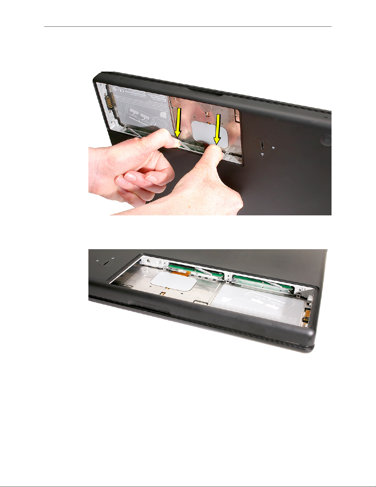
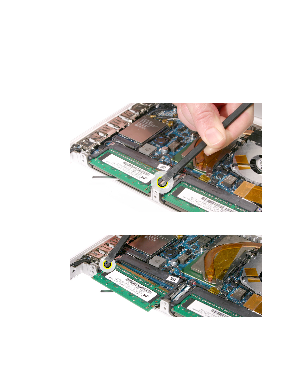
2. Notice the eject bars on each side of the memory card carrier. Use a black stick to push and
slide the eject bar down the side of the carrier.
3. Repeat step 2 on the other side of the memory card carrier until the memory card pops out.
MacBook (13-inch) Take Apart — Memory 28
Page 29

Hard Drive
Tools
• ESD wrist strap and mat
• Black stick (Apple part number 922-5065) or other nonconductive nylon or plastic atblade
tool
Preliminary Steps
Before you begin, remove
• Battery
• RAM door
Part Location
MacBook (13-inch) Take Apart — Hard Drive 29
Page 30
Procedure
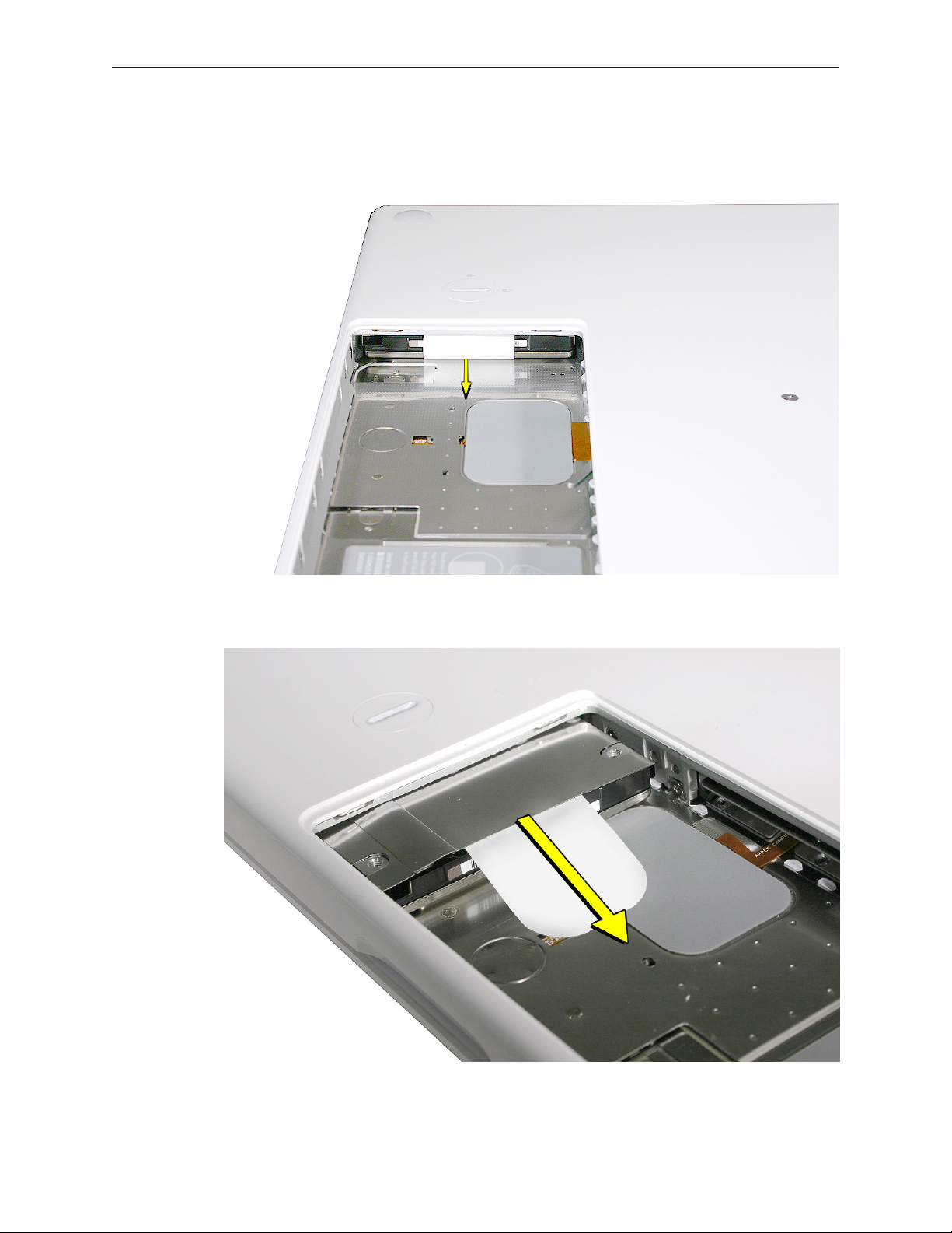
1. If the hard drive pull-tab is tucked in, use a black stick to unroll it.
2. Pull the tab straight out to slide the drive out from the rubber rails in the battery bay.
MacBook (13-inch) Take Apart — Hard Drive 30
Page 31
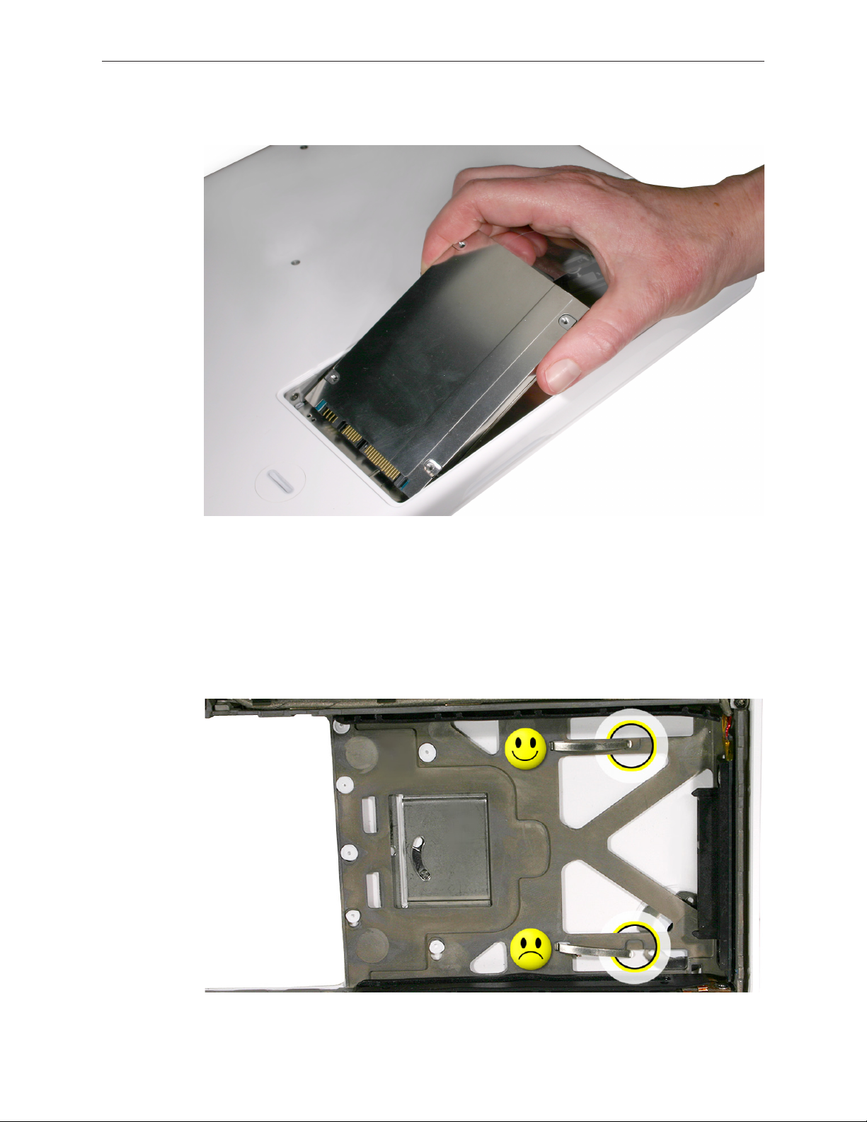
3. Hold the drive only by the sides when removing and replacing it.
4. Install the replacement hard drive, and reassemble and test the computer.
Important: After a new hard drive replacement, you must update the operating system to
Mac OS X version 10.4.6 or later.
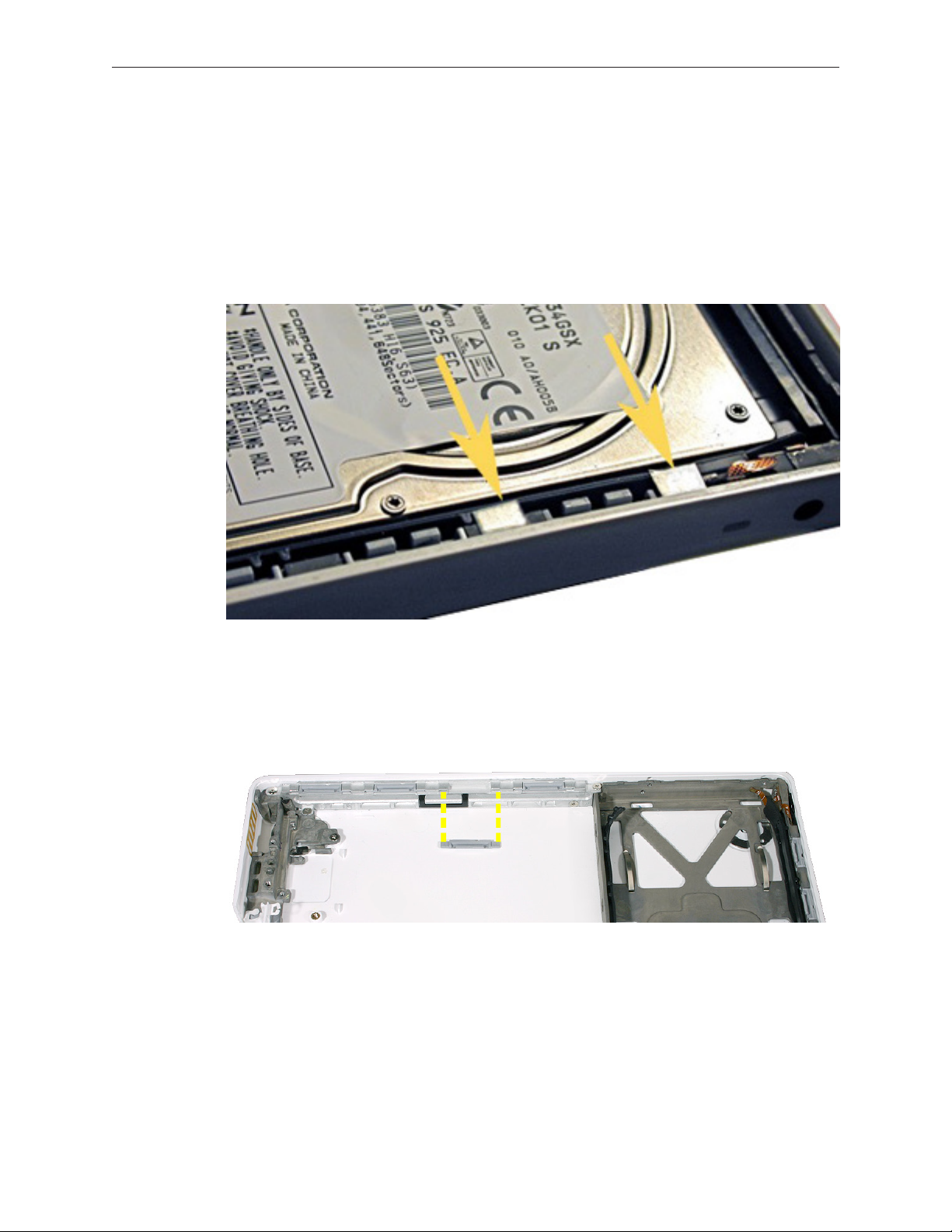
Replacement Note: If you are installing the hard drive while the top case is o, make sure
the two bottom case spring guides are aligned with the notches in the bottom case. The
image below shows the top spring centered and the bottom spring o center.
MacBook (13-inch) Take Apart — Hard Drive 31
Page 32

Replacement Note: Two types of screws are used on the hard drive. If you need to replace
them, note that the shoulder screws are installed closest to the pull tab. (Do not install
screws on top of the drive.)
MacBook (13-inch) Take Apart — Hard Drive 32
Page 33
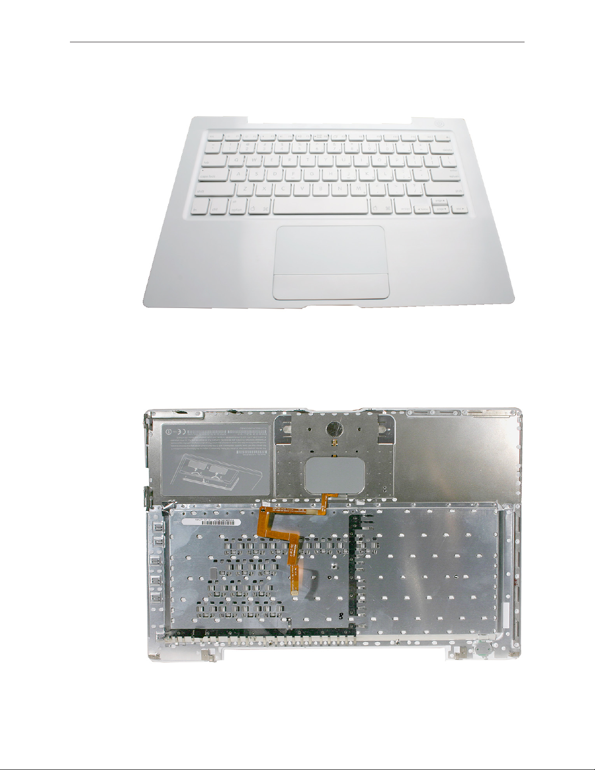
Top Case (with Keyboard)
Tools
• ESD wrist strap and mat
• Magnetic Phillips #0 screwdriver
• Magnetic Phillips #00 screwdriver (preferably with a long handle)
• Black stick (Apple part number 922-5065) or other nonconductive nylon or plastic atblade
tool
• Access card (Apple part number 922-7172) to open the top case
• Clean, soft, lint-free cloth
Preliminary Steps
Before you begin, remove
• Battery
• RAM door
Part Location
MacBook (13-inch) Take Apart — Top Case 33
Page 34
Procedure
Caution: To prevent scratches or other cosmetic damage to the computer housing, use a soft
cloth as a protective layer when removing and installing the external screws.
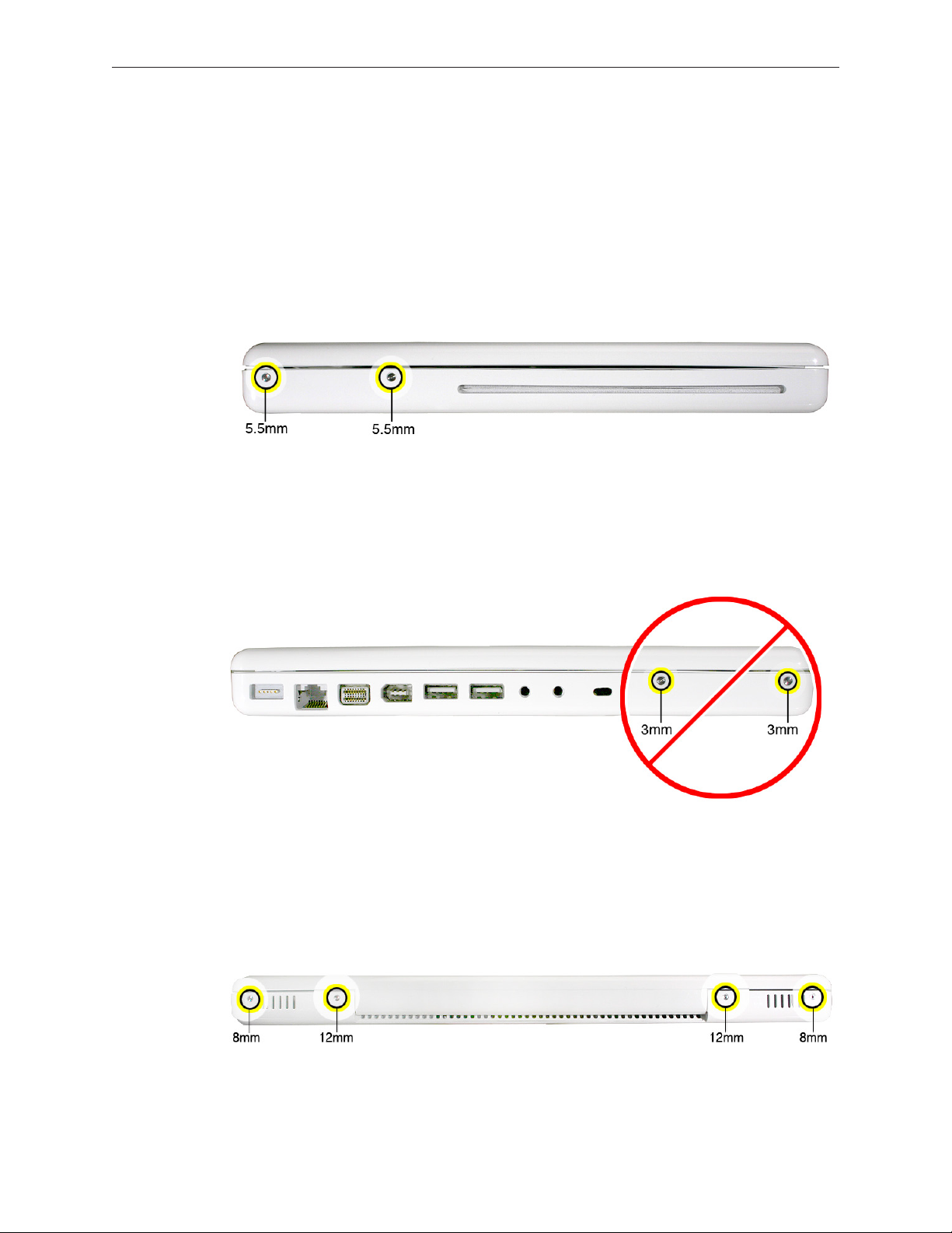
1. With the computer upright, remove the two identical 5.5-mm long shoulder screws from the
right side of the computer.
Replacement Caution: When installing these top case screws, do not press on the area over
the slot drive. The slot-drive bezel could be damaged with too much pressure.
2. Important: Notice the two screws at the left side of the computer. Although they can be
removed, they exist for cosmetic purposes only and do not require removal. If they are
removed, however, be sure to reinstall the two identical 3-mm long shoulder screws at
the corner near the ports. Do not use longer screws.
3. At the back of the computer, remove the four #0 Phillips screws (two at each side) near the
display hinge--
• Two 12-mm long shoulder screws that are closest to the hinge
• Two 8-mm long shoulder screws at the back corners of the computer
MacBook (13-inch) Take Apart — Top Case 34
Page 35
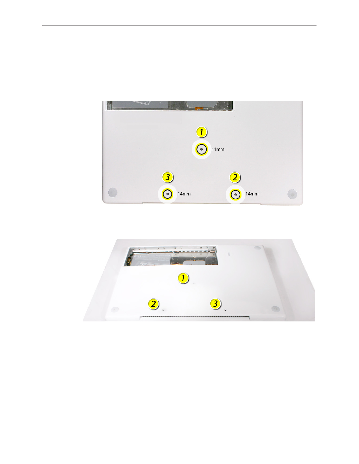
4. Turn over the computer, and on the outside of the bottom case, remove the three #0 Phillips
screws:
• Two 14-mm long screws near display hinge
• One 11-mm long at center of bottom case
Replacement Caution: Do not put one of the longer screws in the center screw hole or it
will damage the logic board.
Replacement Caution: When installing the three bottom case screws, install them in the
order shown.
MacBook (13-inch) Take Apart — Top Case 35
Page 36

5. Notice the long row of #0 Phillips screws at the front edge of the battery bay.
6. Important: Remove only the four screws shown. Remove the 3-mm long identical screws as
follows:
Starting at the corner closest to the battery connector, skip the rst screw, then remove the
second, fourth, seventh, and ninth screw.
Tip: To help remember the screw sequence, think of it as “2, 4, 7, 9 loosens the top case every
time.”
7. In the battery bay, remove the two 6-mm long identical screws that are on both outer sides
of the battery connector. Do not remove the two screws that are closest to the battery
connector.
MacBook (13-inch) Take Apart — Top Case 36
Page 37

8. In the battery bay, use a long-handled screwdriver to remove the three #00 Phillips screws at
the inner edge of the battery bay near where the RAM slots are located:
• Two identical 3-mm long screws
• One longer 4.5-mm long screw at the corner of the battery bay nearest the battery
connector
Because this is a recessed area, the screwdriver has to go in at an angle. Keep the screwdriver
in line with the screw head as much as possible.
Replacement Caution: When installing these three screws, an incorrect installation could
cause the reassembled computer to wobble in use. To prevent a wobble symptom, use light
pressure to hold the top case onto the assembly when installing the screws.
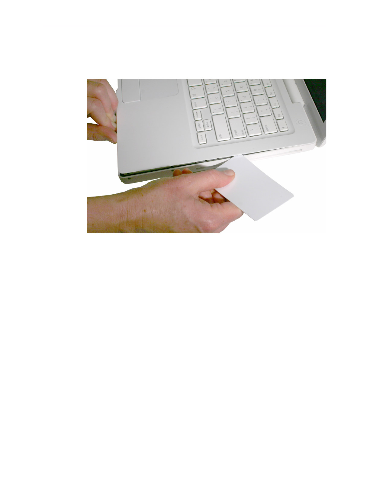
9. Open the display to a 90-degree angle or wider.
10. Warning: Inserting a tool too far or performing this step too quickly could break some of the
snaps that secure the top case. Be especially careful with the left front corner of the top case.
Starting at the left corner and working in a counter-clockwise direction, use an access card
tool to open the gap along the front of the top case, around the perimeter, and to the right
side above the optical drive slot.
MacBook (13-inch) Take Apart — Top Case 37
Page 38
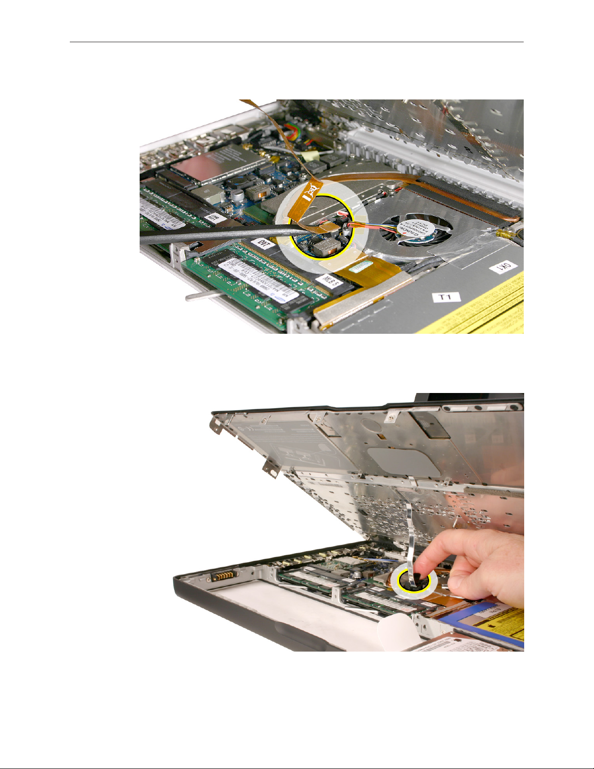
11. With the top and right side gap opened, tilt up—but do not remove—the right edge of the
top case. This motion releases the remaining snaps between the top case and bottom case,
and the slot-load bezel clips become loose as the top case is tilted up.
MacBook (13-inch) Take Apart — Top Case 38
Page 39
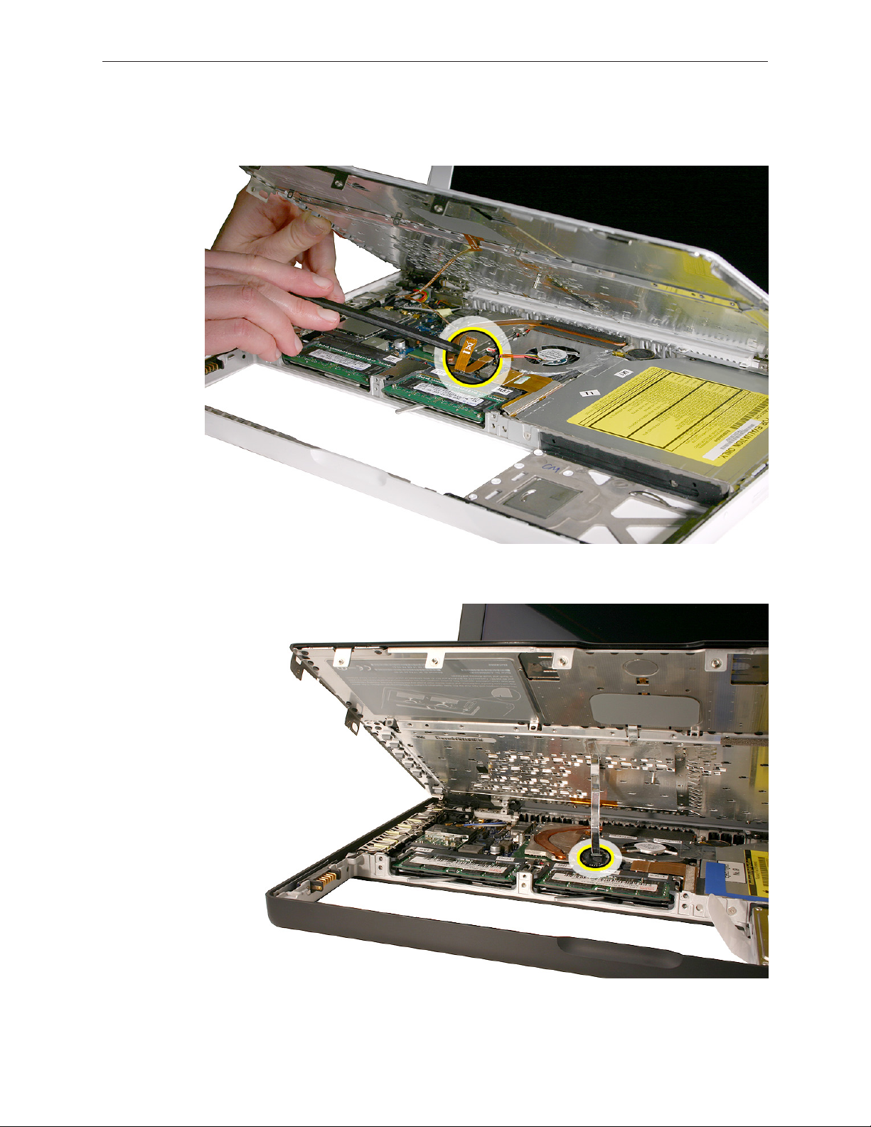
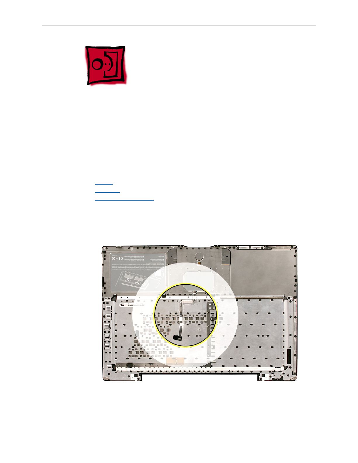
12. Raise up the top case so you can see where the folded trackpad ex cable attaches to the
logic board.
Late 2006 Model:
MacBook (13-inch) Take Apart — Top Case 39
Page 40
13. Use the at end of a black stick to reach in and disconnect the trackpad cable.
For the Late 2006 model, use the pull-tab to disconnect the trackpad cable.
MacBook (13-inch) Take Apart — Top Case 40
Page 41

14. Lift the top case up and away from the computer assembly.
Late 2006 Model:
MacBook (13-inch) Take Apart — Top Case 41
Page 42
15. Refer to the following notes to install the replacement top case, and reassemble and test the
computer.
Replacement Note: The top case includes heatstaked keyboard, webbing, EMI shield, a small
rectangular foam pad, and attached trackpad cable.
Replacement Note: Before replacing the top case, make sure to connect the trackpad ex
cable to the logic board.
MacBook (13-inch) Take Apart — Top Case 42
Page 43
Replacement Warning: Before installing a top case and to avoid top case cracks, make sure
two shims are positioned as shown. If the shims are missing or need replacement,
• Remove two new shims from Apple kit 922-9015 —a sheet of 500 clear shims.
• Place shims adhesive-side-down where shown.
• Make sure shims do not block bottom case clips.
• Important: Both shims should be installed. However, if the shim on the left prevents the
top case from latching or if it creates a gap greater than 0.4 mm between the top and
bottom case, you can remove the left shim.
Replacement Caution: If any of the four bezel clips at the slot-load bezel come loose, simply
insert them back in the slots. Make sure they are in place while reassembling the computer
and before installing the top case. Install the right side of the top case rst (near the disc
bezel) to lock the bezel clips and prevent any of the clips from becoming loose inside the
computer.
MacBook (13-inch) Take Apart — Top Case 43
Page 44
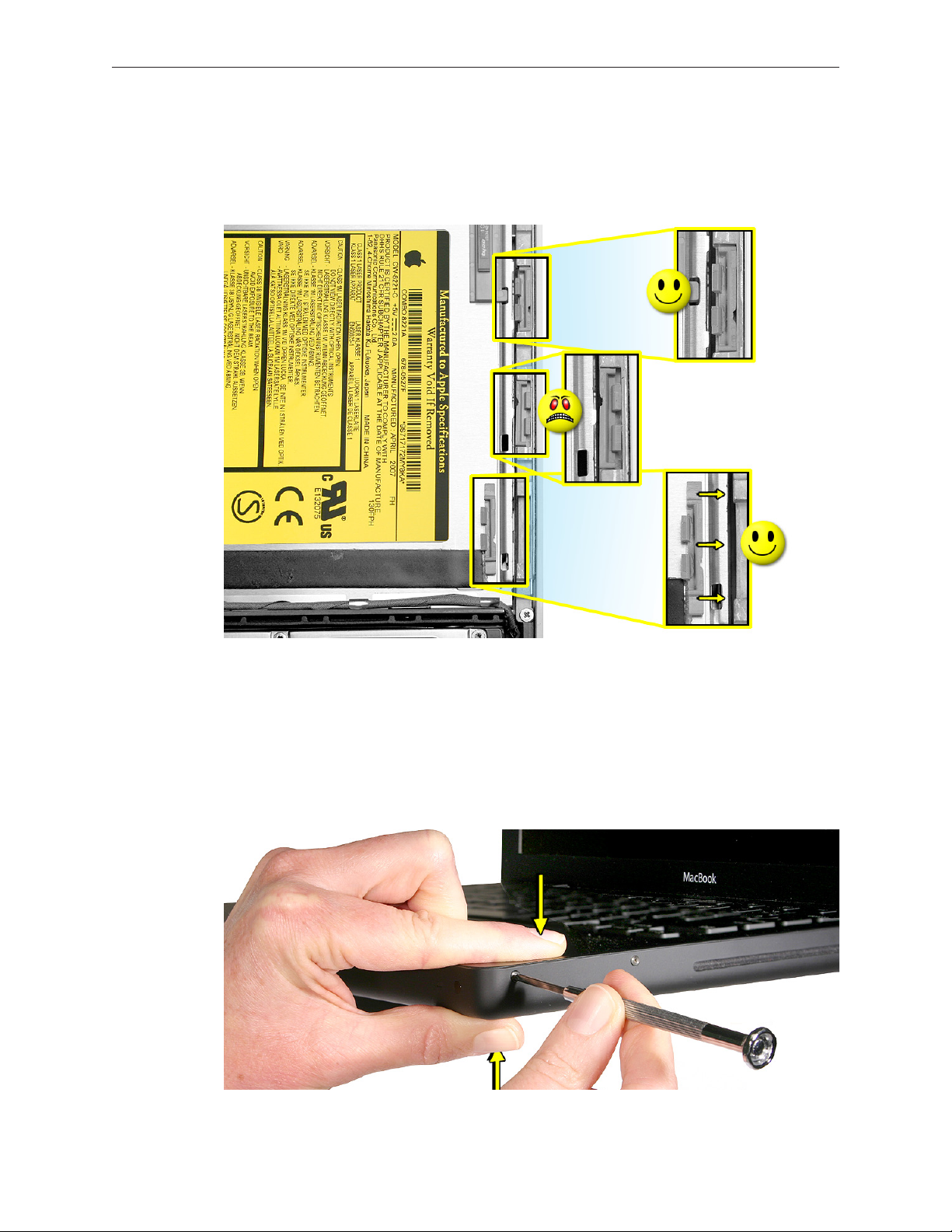
Replacement Caution: If the four bezel clips are shaped as shown below, make sure any
loose clips are inserted correctly in the slot-load bezel. The top case may not t if the bezel
clips are installed upside down or backwards. Make sure all four clips are in place while
reassembling the computer and before installing the top case.
Replacement Note: Install the right side of the top case rst (near the disc bezel). Then
starting from the right, secure the snaps by pressing along the outer edge of the top case in
a clockwise direction around the front and left side of the top case.
Replacement Caution: When installing the exterior screws and the battery bay screws, apply
light pressure to the top case to ensure top case ts to the bottom case without any gaps.
Replacement Note: Pinch the top case to the bottom case as you secure the screws.
MacBook (13-inch) Take Apart — Top Case 44
Page 45

Replacement Note: When installing the screws at the rear corners of the bottom case, insert
an access card tool between the top case and the display to maintain light pressure as the
screws are tightened.
MacBook (13-inch) Take Apart — Top Case 45
Page 46
Top Case/Display Bezel Kit: White Only
New Kit Available in June 2010
As of June, a new kit is available for top case replacement in the U.S. The kit contains:
• white top case with keyboard
• white display bezel
Before Ordering Parts
When replacing a white top case or display bezel, order the new kit to replace both parts in one
repair.
Model Old Part Numbers New Kit Part Number
MacBook (13-inch Late 2006) 922-7885 top case with keyboard
922-7776 display bezel
MacBook (13-inch Mid 2007) 922-8125 top case with keyboard
922-7776 display bezel
922-9591 top case with
keyboard and display
bezel
922-9592 top case with
keyboard and display
bezel
Although the kit applies to white models only, the Take Apart instructions are unchanged for
• Top Case with Keyboard
• Display Bezel
Note About International Parts
Check the Service Parts Database (GSX) for international kit part numbers (with language-specic
keyboards) coming soon.
MacBook (13-inch) Take Apart — Top Case 46
Page 47
Trackpad Cable (Late 2006 Model Only)
Tools
• ESD wrist strap and mat
• Black stick (Apple part number 922-5065) or other nonconductive nylon or plastic atblade
tool
Preliminary Steps
Before you begin, remove
• Battery
• RAM door
• Top case with keyboard
Part Location
MacBook (13-inch) Take Apart — Trackpad Cable (Late 2006 Model Only) 47
Page 48

Procedure
1. Place the top case (keyboard side down) on a clean surface.
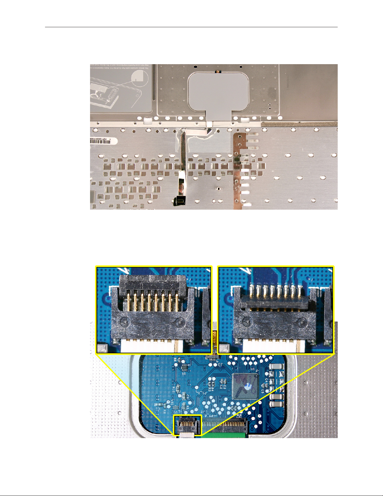
Replacement Note: Refer to the following image when attaching a replacement trackpad
cable. The folds in the cable and the areas that adhere to the top case should appear as
shown.
2. Use a black stick to start to peel up the clear strip of tape.
MacBook (13-inch) Take Apart — Trackpad Cable (Late 2006 Model Only) 48
Page 49

3. Hold the trackpad cable in place as you peel up—but do not remove—the tape.
4. Peel up the mylar shield that protects the trackpad circuitry.
MacBook (13-inch) Take Apart — Trackpad Cable (Late 2006 Model Only) 49
Page 50
Note: The shape of the mylar shield may dier slightly. This one includes a squared-o tab:
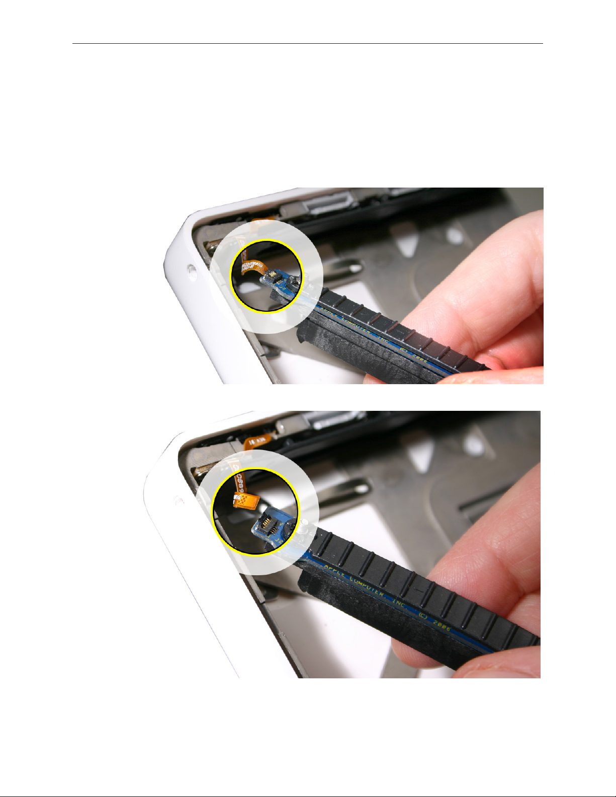
5. Caution: The trackpad cable locking lever at the top of the connector is fragile. Use a black
stick to carefully tilt up the lever until it is vertical (as shown by the detailed image on right).
Replacement Note: When locking the trackpad cable lever, make sure it is completely
closed, as shown by the detailed image on left below.
MacBook (13-inch) Take Apart — Trackpad Cable (Late 2006 Model Only) 50
Page 51

6. With the cable locking lever open, pull the cable down to remove it from the connector.
7. Carefully peel up the trackpad cable from where it adheres to the underside of the top case.
8. Install the replacement trackpad cable, and reassemble and test the computer.
MacBook (13-inch) Take Apart — Trackpad Cable (Late 2006 Model Only) 51
Page 52

AirPort Extreme Card
Tools
• ESD wrist strap and mat
• Black stick (Apple part number 922-5065) or other nonconductive nylon or plastic atblade
tool
• Magnetic Phillips #0 screwdriver
Preliminary Steps
Before you begin, remove
• Battery
• RAM door
• Top case with keyboard
Part Location
MacBook (13-inch) Take Apart — AirPort Extreme Card 52
Page 53

Procedure
Caution: When servicing the computer, be especially careful when working near the two springs
on the logic board. Although the springs are exible, they can be inadvertently torn, bent, or
broken if a cable gets caught on them. A logic board might be considered unusable with one or
more damaged springs. Check the structural integrity of the springs before completing a repair.
1. Remove the 8.5-mm long screw (that also functions as the left speaker cable ground pin)
from the upper right corner of the board. (The thick head on this screw helps identify it.)
2. Remove the 3-mm long screw from the upper left corner of the board.
MacBook (13-inch) Take Apart — AirPort Extreme Card 53
Page 54
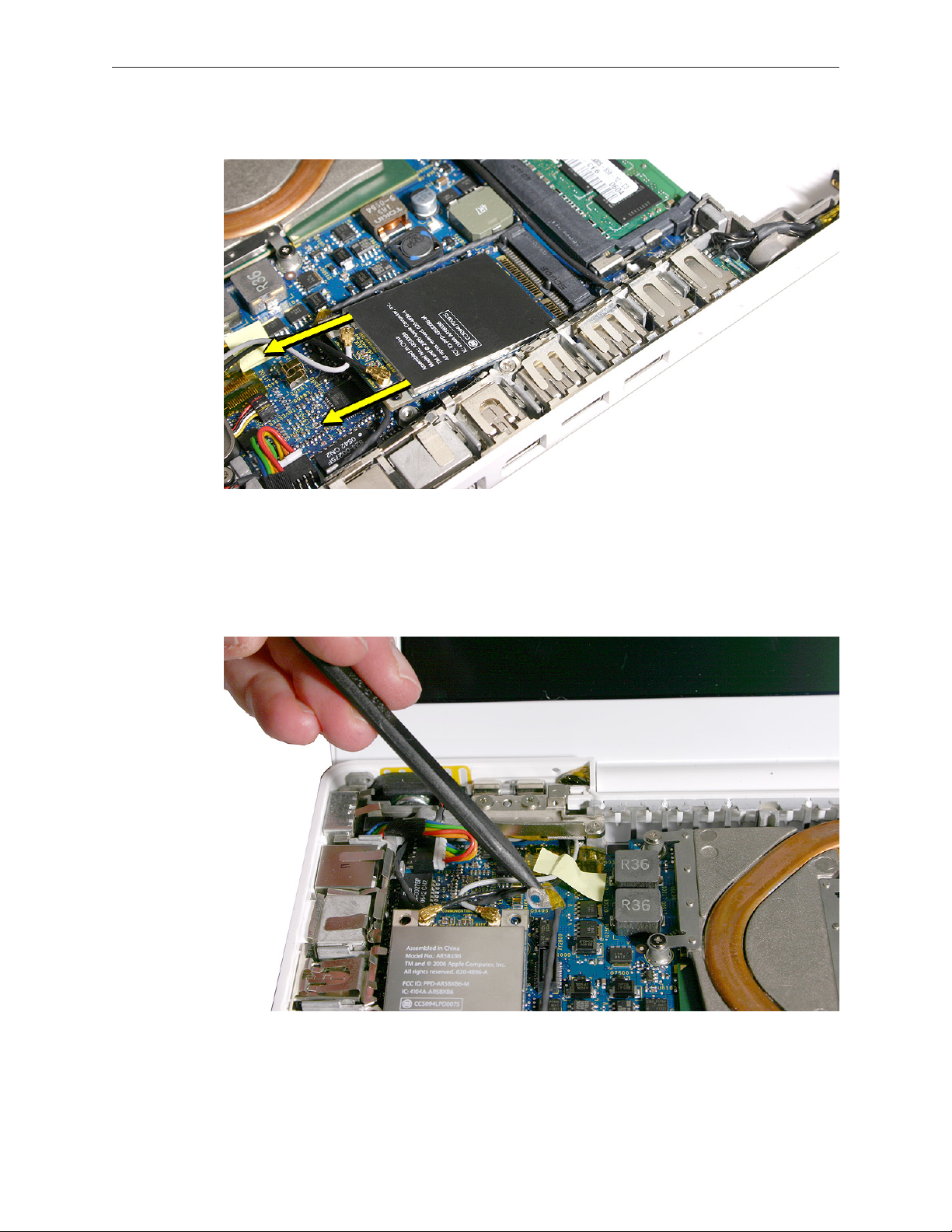
3. Pull the card up slightly and out of the card socket on the logic board.
4. Use a black stick to move aside the speaker cable.
5. Disconnect the two cables from the AirPort Card. Note that the black cable is on the left and
the gray cable is on the right.
Tip: To remember the cable locations, think “Left = bLack; Right = gRay.”
MacBook (13-inch) Take Apart — AirPort Extreme Card 54
Page 55

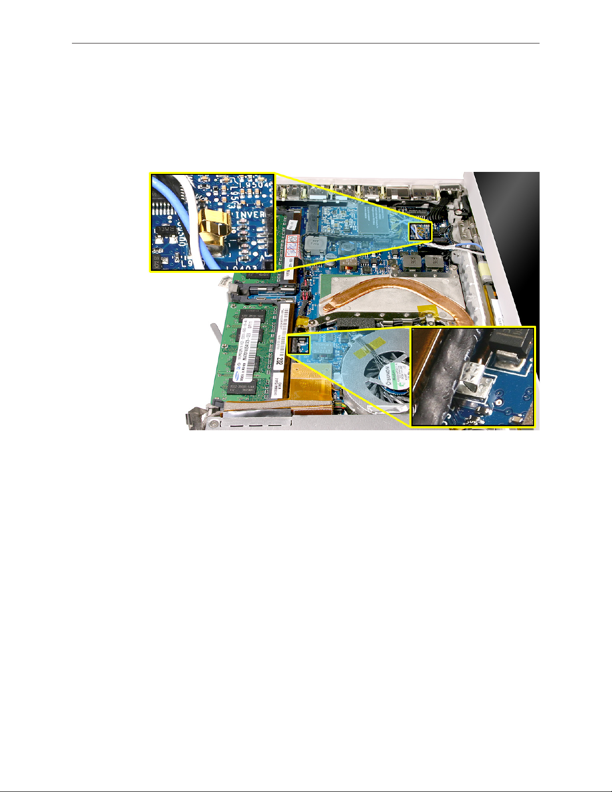
Late 2006 Model: This model has three antenna cables. Disconnect the black, blue, and gray
cables.
6. Install the replacement AirPort Card, and reassemble and test the computer.
Replacement Note: If the computer model that you are servicing includes tape over the
antenna cables, reapply the tape where shown.
MacBook (13-inch) Take Apart — AirPort Extreme Card 55
Page 56
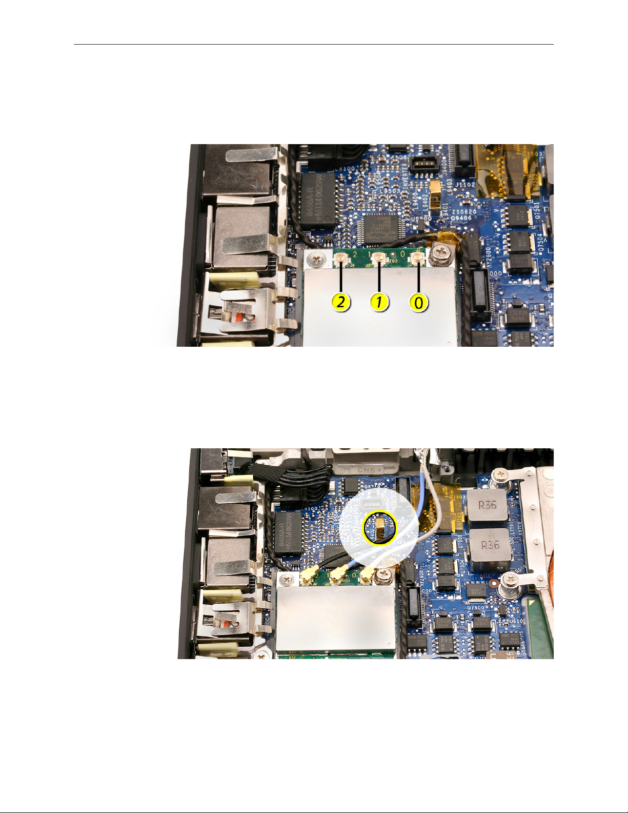
Late 2006 Model Replacement Note: Notice that the AirPort Card has numbers 2, 1, and 0
printed on the card. The numbers correspond to the antenna cable colors where 2 = black, 1
= blue, and 0 = gray.
Replacement Caution: When connecting the AirPort antenna cables, make sure the cables
do not obstruct the gold-colored spring on the logic board. If one of the cables were caught
in the folds of the spring, the cable or spring could be damaged when the top case was
installed.
MacBook (13-inch) Take Apart — AirPort Extreme Card 56
Page 57

MagSafe DC-In Board
Tools
• ESD wrist strap and mat
• Magnetic Phillips #0 screwdriver
• Black stick (Apple part number 922-5065) or other nonconductive nylon or plastic atblade
tool
Preliminary Steps
Before you begin, remove
• Battery
• RAM door
• Top case with keyboard
Part Location
MacBook (13-inch) Take Apart — MagSafe DC-In Board 57
Page 58
Procedure
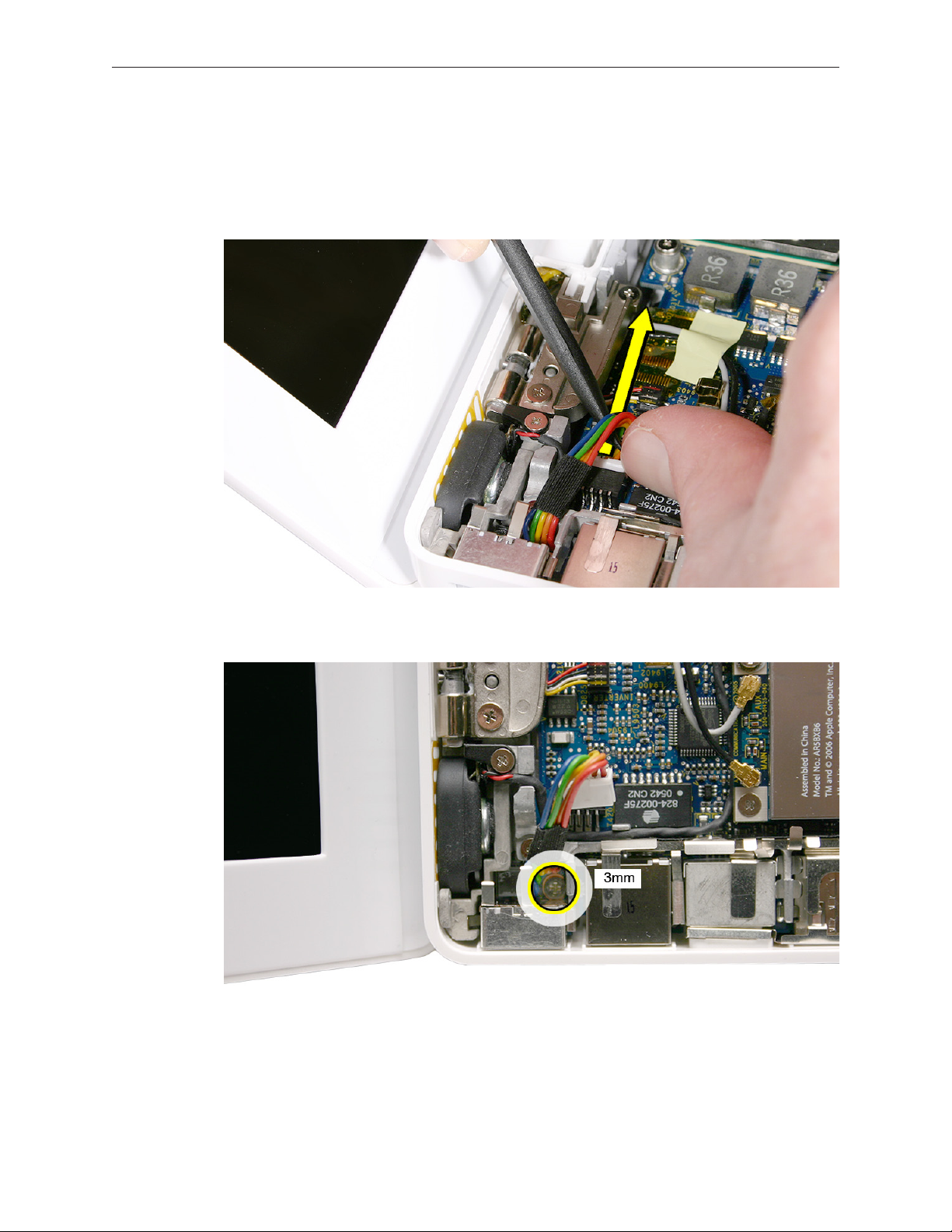
1. Place a black stick under the DC-in connector cables to help disconnect the connector, then
pull the connector away from its connection on the logic board. (Note: Although the cables
are solid black on the Late 2006 model, the steps are the same.)
Remove the 3-mm long screw from the MagSafe DC-in board.
Caution: The DC-in port is magnetic. Be careful that it doesn’t pick up screws or other small
parts.
MacBook (13-inch) Take Apart — MagSafe DC-In Board 58
Page 59

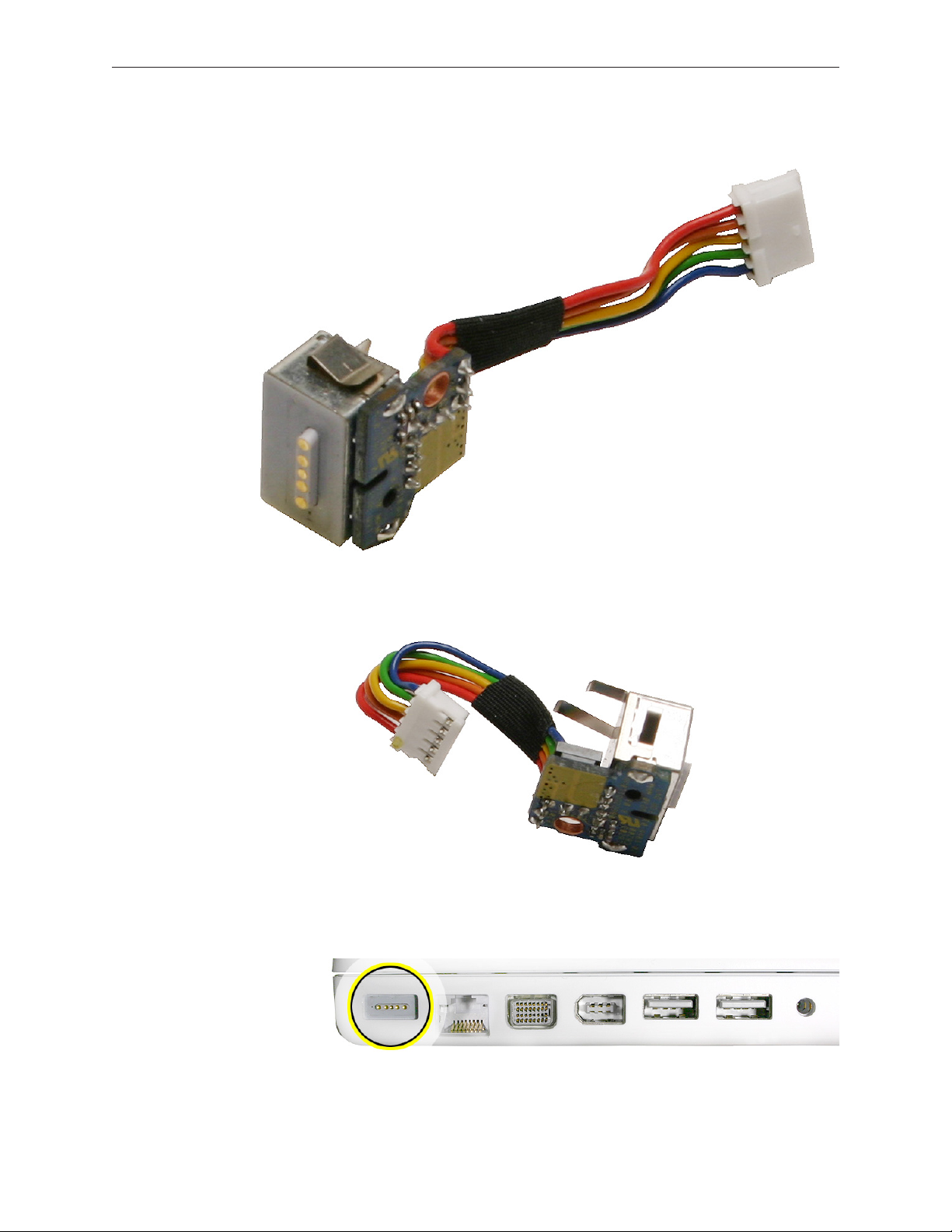
2. From the port side, use a black stick to help tilt up the MagSafe DC-in board and remove it
from the logic board.
Replacement Note: Make sure the folded side of the EMI shield ts over the I/O frame rib so
that the rib is sandwiched between the anges of the EMI shield.
Replacement Note: If installing a new MagSafe DC-in board, rst peel o the protective
membrane from the MagSafe DC-in board. Then connect the DC-in cable to the connector
on the logic board, and insert the board into the upper left corner of the bottom case. Finally,
install the screw.
MacBook (13-inch) Take Apart — MagSafe DC-In Board 59
Page 60
3. Install the replacement MagSafe DC-in board, and reassemble and test the computer.
Replacement Note: Check that there are no bent EMI ngers on the shield covering the port
area.
Replacement Note: Check the port side of the bottom case to make sure the MagSafe DC-in
port is level with the port opening.
MacBook (13-inch) Take Apart — MagSafe DC-In Board 60
Page 61
Left Speaker
Tools
• ESD wrist strap and mat
• Magnetic Phillips #0 screwdriver
• Black stick (Apple part number 922-5065) or other nonconductive nylon or plastic atblade
tool
Preliminary Steps
Before you begin, remove
• Battery
• RAM door
• Top case with keyboard
Part Location
MacBook (13-inch) Take Apart — Left Speaker 61
Page 62

Procedure
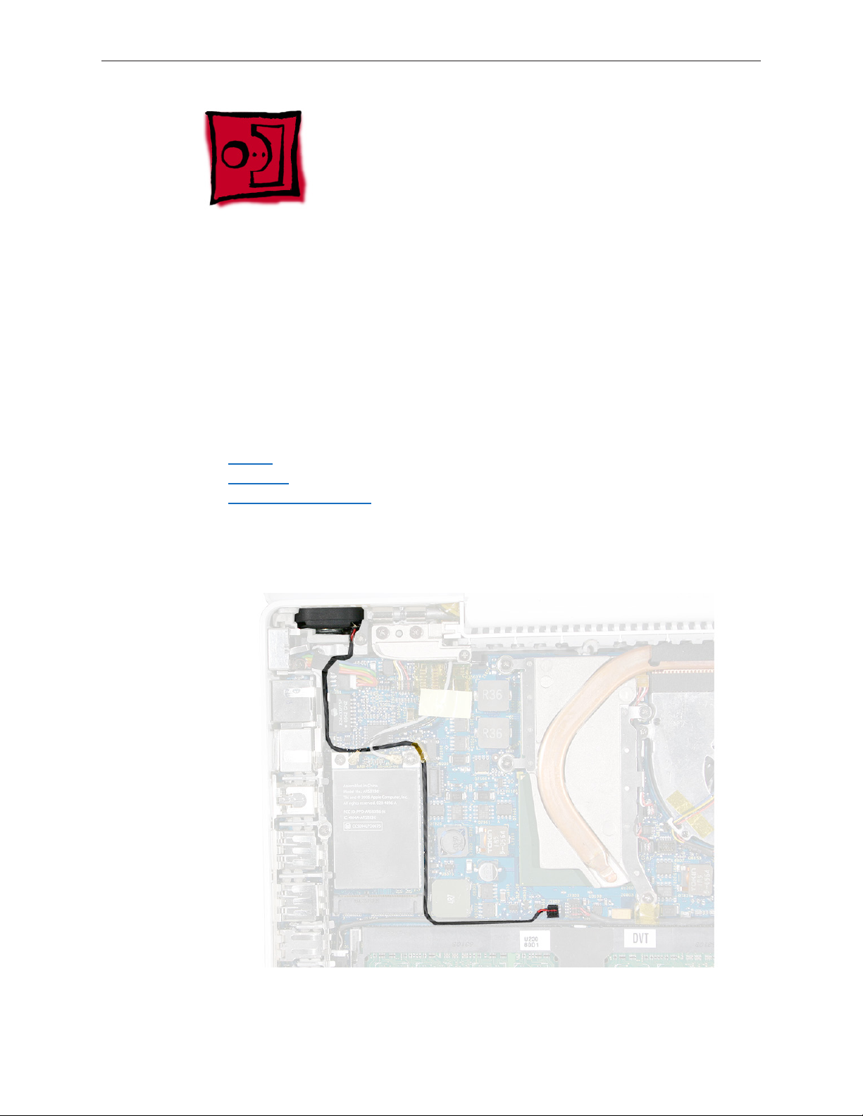
1. Disconnect the speaker cable from the logic board.
2. Remove the 8.5-mm long ground screw at the upper right corner of the AirPort Extreme
Card.
3. Route the cable underneath the AirPort cables.
MacBook (13-inch) Take Apart — Left Speaker 62
Page 63

4. Remove the 6-mm long speaker screw.
5. Pull up on the speaker cable to remove it from the frame.
6. Pivot up the speaker from the left corner.
MacBook (13-inch) Take Apart — Left Speaker 63
Page 64

7. Route the speaker cable underneath the DC-in cable.
8. Install the replacement speaker cable, and reassemble and test the computer.
Replacement Note: To prevent a pinched cable, make sure the cable is routed as shown.
MacBook (13-inch) Take Apart — Left Speaker 64
Page 65

Battery Connector with Sleep Switch
Tools
• ESD wrist strap and mat
• Magnetic Phillips #0 screwdriver
• Black stick (Apple part number 922-5065) or other nonconductive nylon or plastic atblade
tool
Preliminary Steps
Before you begin, remove
• Battery
• RAM door
• Top case with keyboard
Part Location
MacBook (13-inch) Take Apart — Battery Connector with Sleep Switch 65
Page 66

Procedure
Important: When replacing the battery connector/sleep switch, make sure the arrangement
of pins on the connector exactly match the pin openings on the logic board. If the cable
does not match the logic board, discard the cable and order the correct matching cable.
Caution: Do not touch the raised section of the sleep switch connector. It is fragile and could
break.
1. Remove the two 4.5-mm long shoulder screws from the frame at the battery connector.
Replacement Caution: Make sure the screws are the proper length. A longer screw could
damage the board.
MacBook (13-inch) Take Apart — Battery Connector with Sleep Switch 66
Page 67

2. Tilt up the battery connector end of the board.
3. If provided, remove the single screw that secures the battery cable clip to the I/O frame.
MacBook (13-inch) Take Apart — Battery Connector with Sleep Switch 67
Page 68

4. Tilt up the battery cable clip, and remove it from the computer assembly.
Replacement Note: Be sure to install the battery cable clip when reassembling the
computer.
MacBook (13-inch) Take Apart — Battery Connector with Sleep Switch 68
Page 69

5. Caution: Do not touch the raised section of the sleep switch connector. It is fragile and could
break. Using a black stick, insert it under the cables, and lift up the connector from the logic
board.
Replacement Note: To avoid bending the pins on the sleep switch connector card, make
sure you squarely align the pins over the logic board and keep the connector card level
when installing it. Install the “pins” end of the sleep switch connector rst; then install the
battery connector and screws.
MacBook (13-inch) Take Apart — Battery Connector with Sleep Switch 69
Page 70
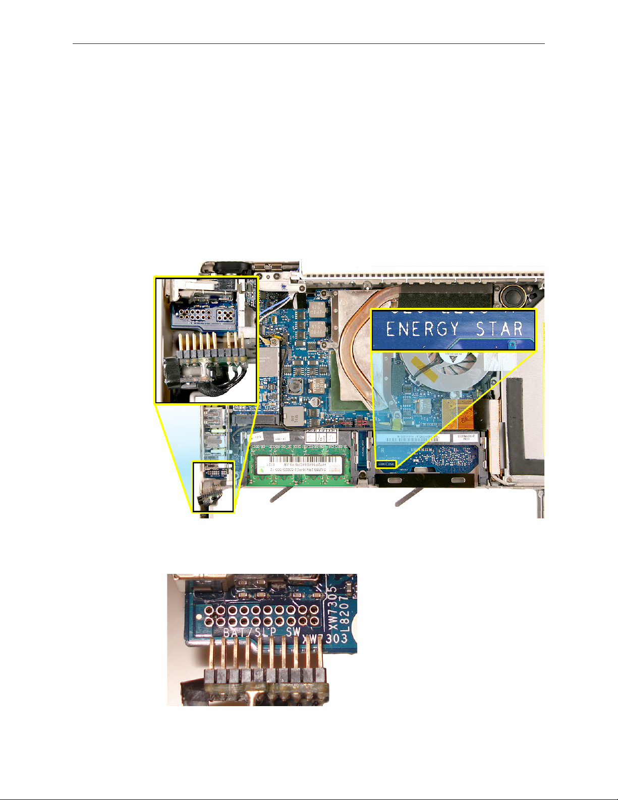
6. Important: When replacing the battery connector/sleep switch, make sure the
arrangement of pins on the connector exactly match the pin openings on the logic
board. If the cable does not match the logic board, discard the cable and order the
correct matching cable.
Replacement Caution: Before installing a new logic board or sleep switch, ensure that the
new part has the same features as the old part. Check the sleep switch area, as follows, for
positive identication:
• If the sleep switch connector has a gap in the two rows of pins between three pins and
the remaining pins, then the logic board must be an Energy Star model with a matching
gap in the pin openings of the sleep switch area. Also, the words “ENERGY STAR” are
printed on the logic board at the second memory card slot.
• If the sleep switch connector has two rows of uninterrupted uniform pins, the logic
board must have matching pin openings (no gap).
MacBook (13-inch) Take Apart — Battery Connector with Sleep Switch 70
Page 71

7. Install the replacement battery connector with sleep switch, and reassemble and test the
computer.
Caution: To avoid pinching the cable, the battery connector cable must be properly
tucked into the cable channel, as shown by the image on the left, below:
Replacement Note: Check that the battery connector can be wiggled to allow for
movement of the battery. If the connector is completely still when grasped, loosen the
screws slightly.
MacBook (13-inch) Take Apart — Battery Connector with Sleep Switch 71
Page 72

Hard Drive Connector
Tools
• ESD wrist strap and mat
• Magnetic Phillips #0 screwdriver
• Black stick (Apple part number 922-5065) or other nonconductive nylon or plastic atblade
tool)
Preliminary Steps
Before you begin, remove
• Battery
• RAM door
• Hard drive
• Top case with keyboard
Part Location
MacBook (13-inch) Take Apart — Hard Drive Connector 72
Page 73

Procedure
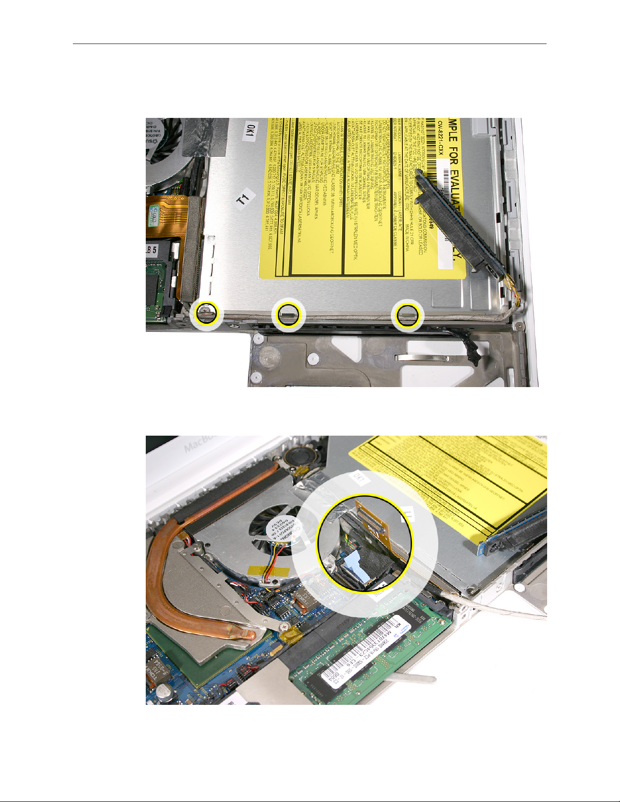
1. Remove the two 6-mm long screws from the hard drive connector at the right front side of
the computer.
2. Carefully lift up the hard drive connector from the bottom case. This action automatically
disconnects the hard drive board from the sleep LED/IR receiver ex cable.
MacBook (13-inch) Take Apart — Hard Drive Connector 73
Page 74
Replacement Caution: Note the tiny connector at the end of the hard drive board. It
connects to the sleep LED/ IR receiver board at the front right corner of the computer via a
tiny ex cable. To reinstall the ex cable, rst peel up the end of the snubber to access the
length of the ex cable. Carefully peel up the ex cable from its adhesive. Using a black stick,
tilt up the tiny ex cable at the right corner. Insert it into the connector on the hard drive
board, and fold down the tiny locking lever on the connector. Without straining the
connection, carefully tilt the hard drive board into place in front of the snubber.
MacBook (13-inch) Take Apart — Hard Drive Connector 74
Page 75
3. Pull up the hard drive connector cable that runs along the bottom edge of the optical drive.
Note the three cable routing guides when reinstalling the cable.
4. Use the two pull tabs to disconnect the optical drive ex cable and the LVDS cable.
MacBook (13-inch) Take Apart — Hard Drive Connector 75
Page 76

5. Use the pull tab to disconnect the hard drive connector cable.
6. Route the hard drive connector cable under the black cables.
MacBook (13-inch) Take Apart — Hard Drive Connector 76
Page 77
7. Install the replacement hard drive connector, and reassemble and test the computer.
MacBook (13-inch) Take Apart — Hard Drive Connector 77
Page 78
Fan
Tools
• ESD wrist strap and mat
• Magnetic Phillips #00 screwdriver
• Black stick (Apple part number 922-5065) or other nonconductive nylon or plastic atblade
tool
Preliminary Steps
Before you begin, remove
• Battery
• RAM door
• Top case with keyboard
Part Location
MacBook (13-inch) Take Apart — Fan 78
Page 79
Procedure
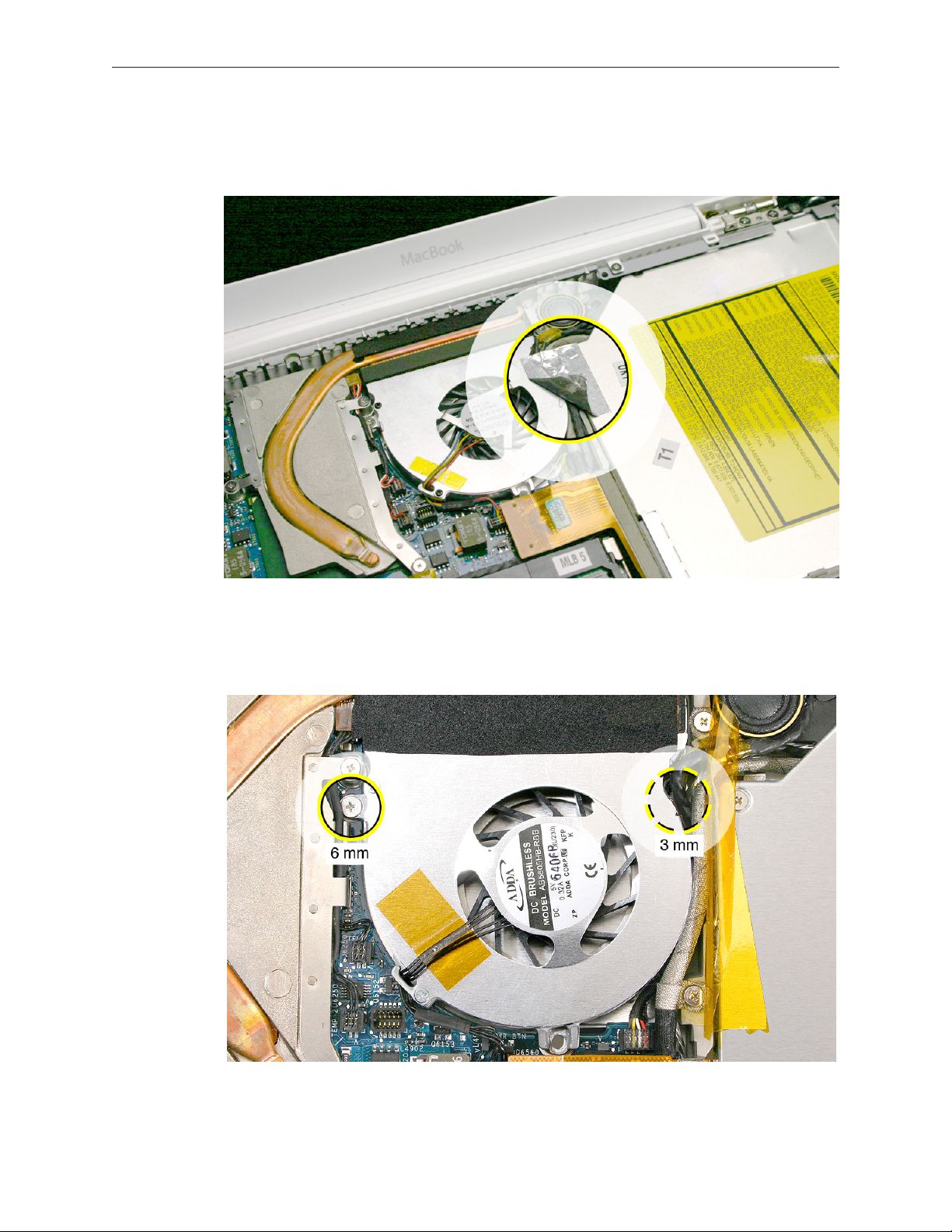
1. Peel up the strip of tape that overlaps the fan near the optical drive.
2. Remove the screws from the fan:
• 6-mm long screw from the upper left
• 3-mm long screw from the upper right (normally hidden underneath the cable bundles)
MacBook (13-inch) Take Apart — Fan 79
Page 80

3. Tilt up the fan and disconnect the fan cable from the logic board.
4. Holding the fan tilted up from the bottom case, peel away the adhesive foam that overlaps
the fan and the heatsink.
Replacement Note: Because the foam strip tears easily, be sure to install a new strip of
adhesive foam before reassembling the computer.
5. Install the replacement fan, and reassemble and test the computer.
Replacement Note: Make sure the cables are fully tucked in the channel between the fan
and the optical drive. Reapply the tape or apply new tape.
MacBook (13-inch) Take Apart — Fan 80
Page 81

Heatsink
Tools
• ESD wrist strap and mat
• Magnetic Phillips #0 screwdriver
• Black stick (Apple part number 922-5065) or other nonconductive nylon or plastic atblade
tool
• Alcohol wipes
• Thermal grease syringe (Apple part number 922-7144)
• Felt-tip pen (optional)
Preliminary Steps
Before you begin, remove
• Battery
• RAM door
• Top case with keyboard
• Fan
Part Location
MacBook (13-inch) Take Apart — Heatsink 81
Page 82

Procedure
1. Remove the four identical 8-mm long screws from the heatsink.
Note that the screw at the lower right corner anchors a exible ground tab for the speaker
cable that runs along the top of the RAM card carriers. Make sure the tab is sandwiched
between the heatsink and the screw when it is reinstalled.
MacBook (13-inch) Take Apart — Heatsink 82
Page 83
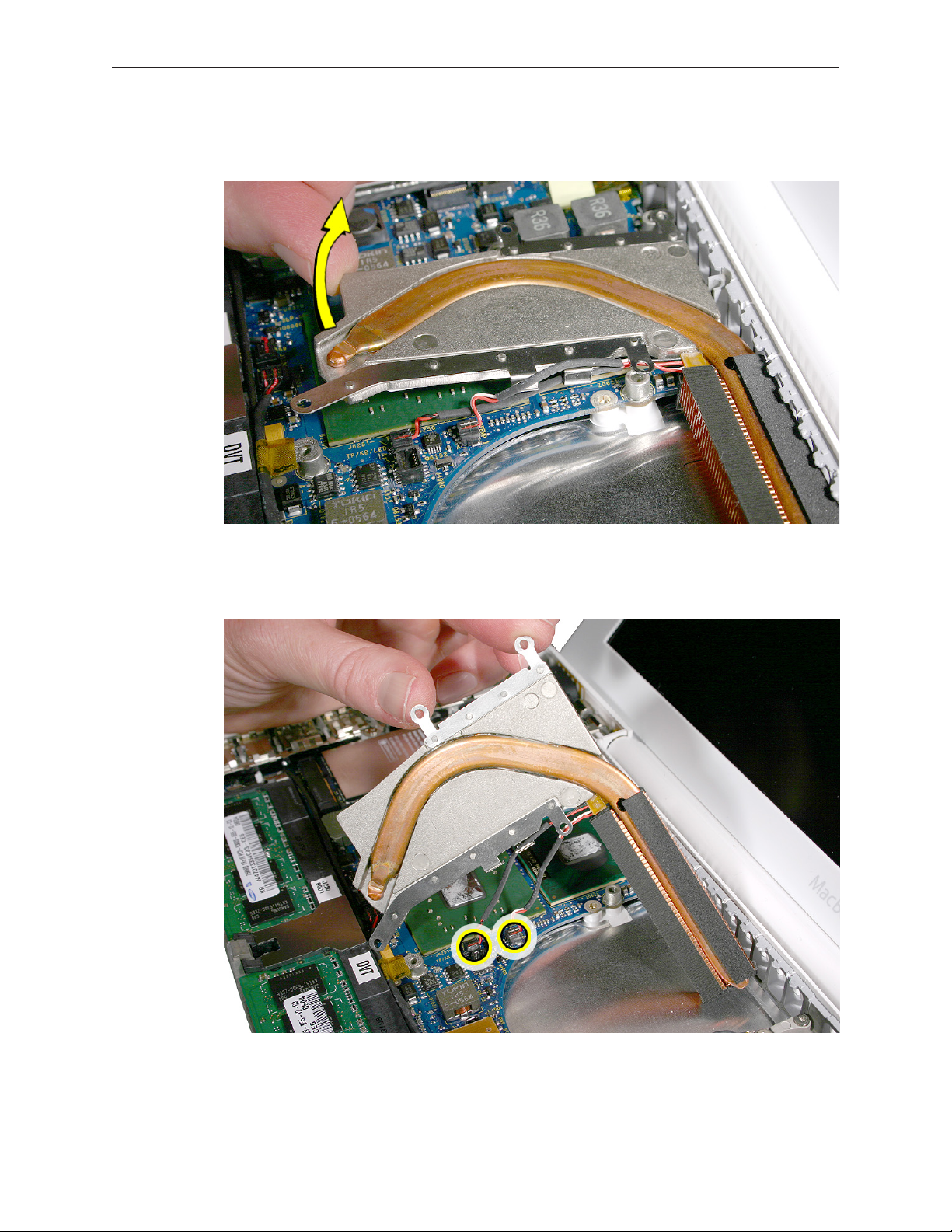
2. Starting at the lower bracket of the heatsink, start to tilt it up to loosen it from the logic
board.
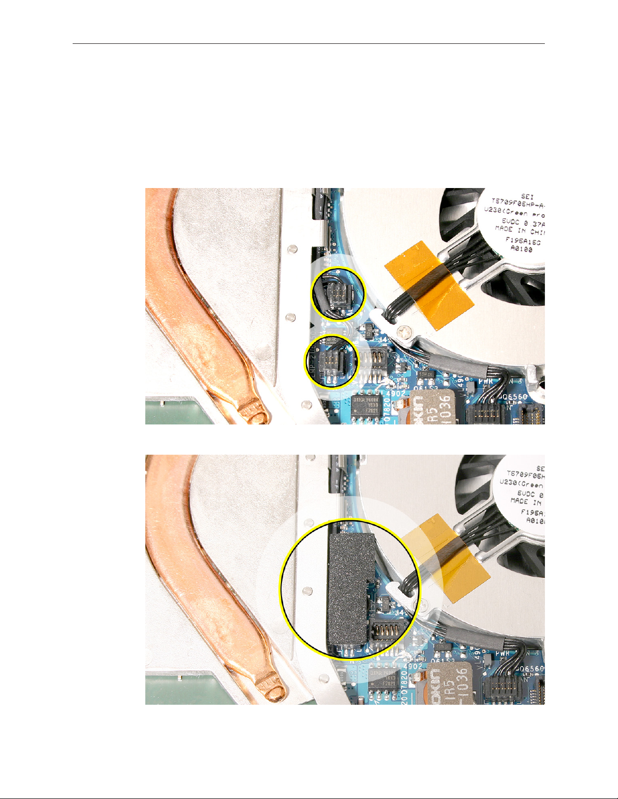
3. Holding the heatsink by its edges, tilt it up and disconnect the two thermistor connectors
from the logic board.
MacBook (13-inch) Take Apart — Heatsink 83
Page 84

Replacement Caution: When installing the heatsink, make sure its two thermistor cables are
routed as shown to prevent cable damage.
Replacement Note: Make sure you install the thermal sponge over the two thermistor
connectors.
4. Important: Anytime the heatsink is removed (even if it is to replace another module), check
the thermal grease as described in the following section.
MacBook (13-inch) Take Apart — Heatsink 84
Page 85
Checking the Thermal Grease
Warning: Whenever the heatsink is separated from the logic board (even if you are
installing the same heatsink or board), the thermal grease must be checked and possibly
replaced. Failure to do so can cause the computer to overheat and be damaged.
1. With the heatsink removed, check the underside of the heatsink:
• If it has a thin sheet of transparent lm covering the square heatsink pads and preapplied thermal grease, then you do not need to reapply thermal grease. Do not remove the
thin lm. Skip step 2 and go to step 3 to clean up any excess thermal grease that might have
squeezed out onto the chips. Then go directly to step 8.
• If you are installing a new heatsink and it is packaged with clear, rigid plastic, remove the
clear plastic from the heatsink plate. Because the heatsink includes pre-applied thermal
grease, skip step 2 and go to step 3. Then go directly to step 8.
MacBook (13-inch) Take Apart — Heatsink 85
Page 86
• If the thermal grease is directly on the heatsink pads (as shown in step 2), continue with
the remaining steps in this procedure.
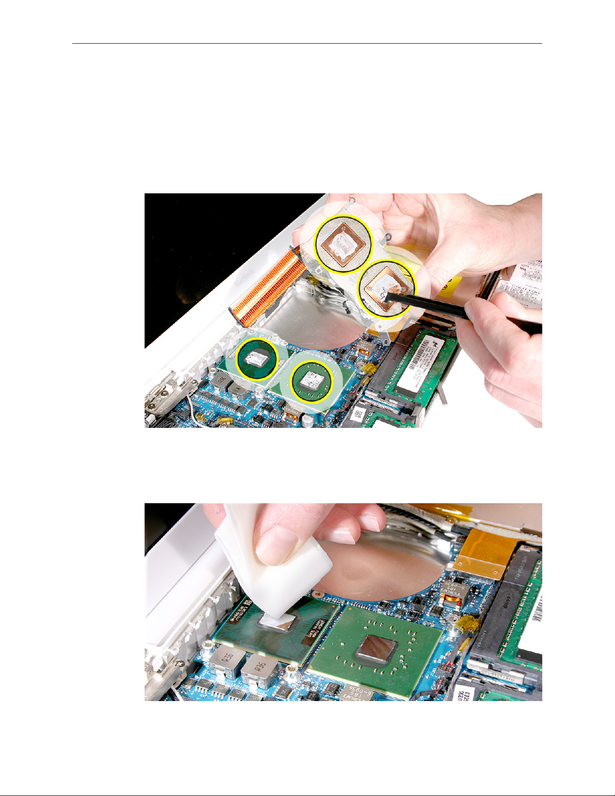
2. Caution: This step is required only when the heatsink and logic board are removed to
replace a later part (such as the bottom case) and the same heatsink and logic board
will be re-installed in the computer.
Use a black stick to remove as much thermal grease as possible from the two chips on the
logic board and the two pads on the heatsink.
3. Use an alcohol wipe to completely clean the residual thermal grease from the two chips. (If
you are replacing the logic board with a new one, skip this step.)
Important: Use extreme care not to damage the logic board components.
MacBook (13-inch) Take Apart — Heatsink 86
Page 87

4. Use an alcohol wipe to completely clean the two pads on the heatsink.
5. Caution: The syringe steps for this procedure are required only when the heatsink and
logic board are removed to replace a later part (such as the bottom case) and when no
new heatsink with pre-applied thermal grease will be installed. Refer to the heatsink
conditions in step 1 for details before attempting to replace the thermal grease.
Note the contents of the syringe of thermal grease.
Important: One syringe (922-7144) contains 0.3 to 0.35 cubic centimeters (cc) of thermal
grease. That is enough for 0.1 to 0.12 cc of grease per chip for up to three chips. Because this
computer has only two chips, the last 1/3 of thermal grease remains in the syringe. Use onethird of the syringe contents per chip. Using a felt-tip pen, mark the 1/3 points on the syringe
before applying the rst dab.
MacBook (13-inch) Take Apart — Heatsink 87
Page 88

6. Using the syringe, put a 0.1 to 0.12 cc dab of thermal grease, in the center, on the mating
surfaces of both chips, as shown below. Apply the grease only up to the line that you marked
on the syringe.
Important: Use one-third of the syringe contents per chip, so in this case, 1/3 of the thermal
grease will be left in the syringe when you are done. Although the amount shown appears
to be plenty of grease, this is the correct amount that has been tested and veried on the
production line.
Important: Avoid unnecessary contact with new thermal material, as dirt and body oils
reduce the material’s conductivity.
MacBook (13-inch) Take Apart — Heatsink 88
Page 89

7. While centering the heatsink pads over the two chips, lower the heatsink onto the logic
board and press on the areas where the screw brackets on the heatsink meet the standos
on the board. Make sure the heatsink is level on the board before installing the screws.
8. Install the heatsink (using the screw sequence shown below), and reassemble and test the
computer.
Note: Make sure the heatsink includes the gray, adhesive sponge strip that sticks to and runs
along the top of the copper pipe. (A new heatsink kit includes the gray strip, ready for
installation.)
MacBook (13-inch) Take Apart — Heatsink 89
Page 90
9. Replacement Note: If you replaced the heatsink from a kit that includes the thermal sponge,
install the thermal sponge over the two thermistor connectors.
• Make sure the connectors are fully seated.
• Remove the adhesive backing from the sponge, and place the sponge adhesive side
down over the two connectors.
• Make sure the sponge sticks to and completely covers both connectors. (The actual
color and appearance of the sponge may vary slightly from what is included in the kit.)
MacBook (13-inch) Take Apart — Heatsink 90
Page 91
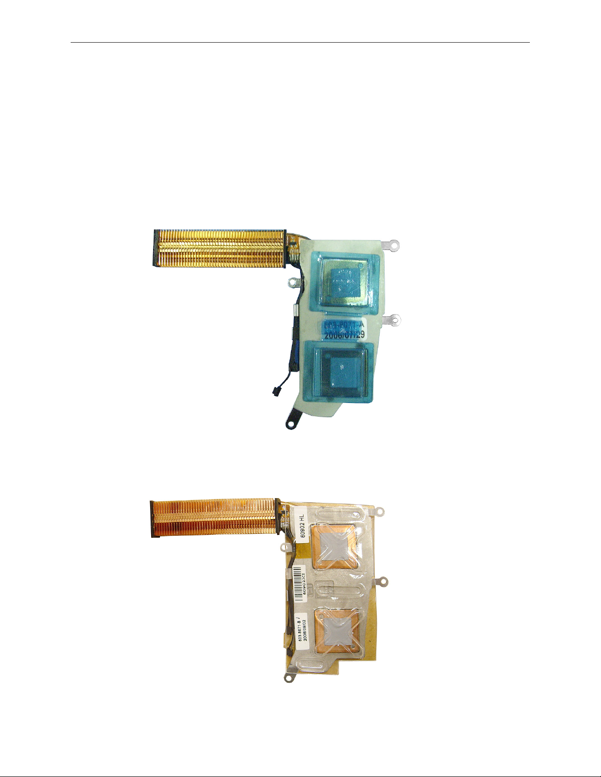
Comparing Heatsinks
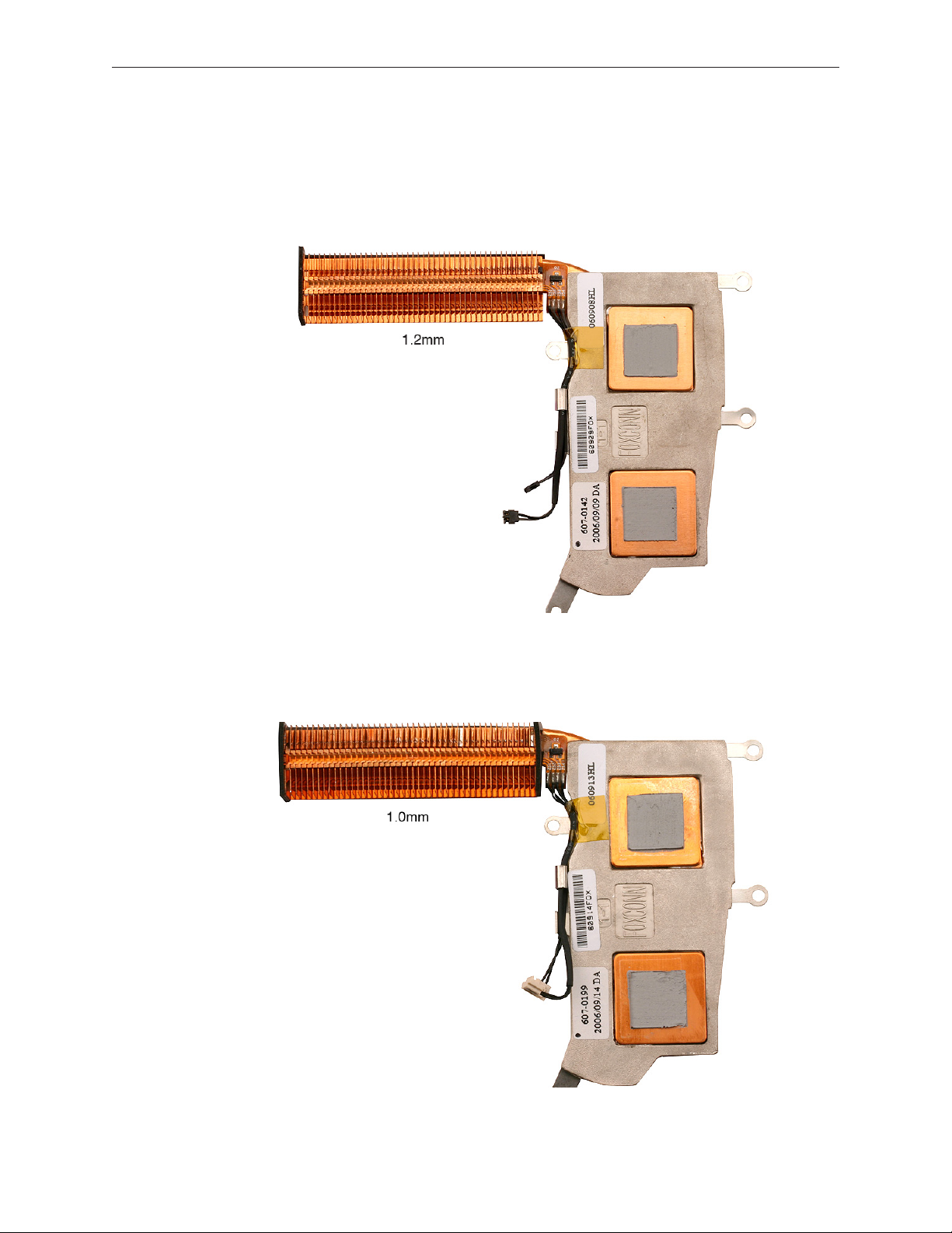
The heatsink referred to as a 1.2 mm heatsink can be identied by the number 607-0142 on its
label and its thin rectangular thermistor connectors. Order Apple part number 076-1242 (which
includes the heatsink, thermal tape, and sponge) to replace a 1.2 mm heatsink.
The heatsink referred to as a 1.0 mm heatsink can be identied by the number 607-0199 on its
label and its thick square thermistor connectors. Order Apple part number 076-1243 (which
includes the heatsink, thermal tape, and sponge) to replace a 1.0 mm heatsink.
MacBook (13-inch) Take Apart — Heatsink 91
Page 92

Bluetooth Holder
Important: The Bluetooth holder is included with a replacement optical drive and should not be
removed unless it is damaged or no longer sticks to the optical drive housing.
Tools
• ESD wrist strap and mat
• Any standard size CD or DVD disc
• Black stick (Apple part number 922-5065) or other nonconductive nylon or plastic atblade
tool
Preliminary Steps
Before you begin, remove
• Battery
• RAM door
• Top case with keyboard
Part Location
MacBook (13-inch) Take Apart — Bluetooth Holder 92
Page 93
Procedure
1. Insert a CD or DVD disc half way into the slot drive to help support the drive and prevent
damage.
2. Use a black stick to slide out the Bluetooth board from its holder.
MacBook (13-inch) Take Apart — Bluetooth Holder 93
Page 94
3. Warning: To prevent damage to the optical drive, do not touch or press anywhere else
on the drive.
4. Use a black stick to carefully pry up the Bluetooth holder from the top of the optical drive.
Make sure you use as little pressure as possible to prevent damage to the drive.
Replacement Note: Peel o the adhesive backing from the Bluetooth holder and apply it to
the drive where shown. Press the holder lightly to make sure it adheres to the drive.
MacBook (13-inch) Take Apart — Bluetooth Holder 94
Page 95
5. Install the replacement Bluetooth holder, remove the optical drive disc, and reassemble and
test the computer.
MacBook (13-inch) Take Apart — Bluetooth Holder 95
Page 96

Optical Drive
Tools
• ESD wrist strap and mat
• Magnetic Phillips #0 screwdriver
• Black stick (Apple part number 922-5065) or other nonconductive nylon or plastic atblade
tool
Preliminary Steps
Before you begin, remove
• Battery
• RAM door
• Top case with keyboard
Part Location
MacBook (13-inch) Take Apart — Optical Drive 96
Page 97
Procedure
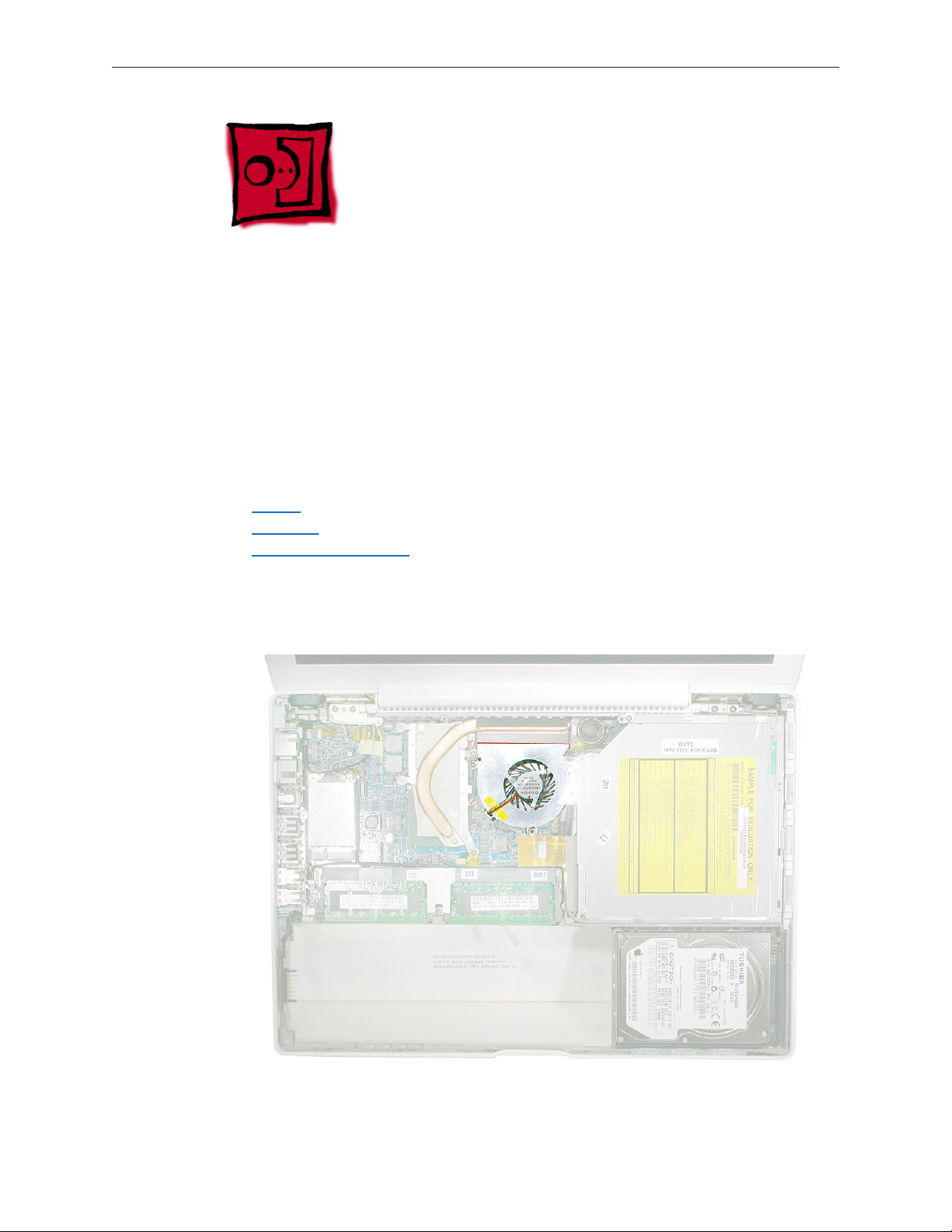
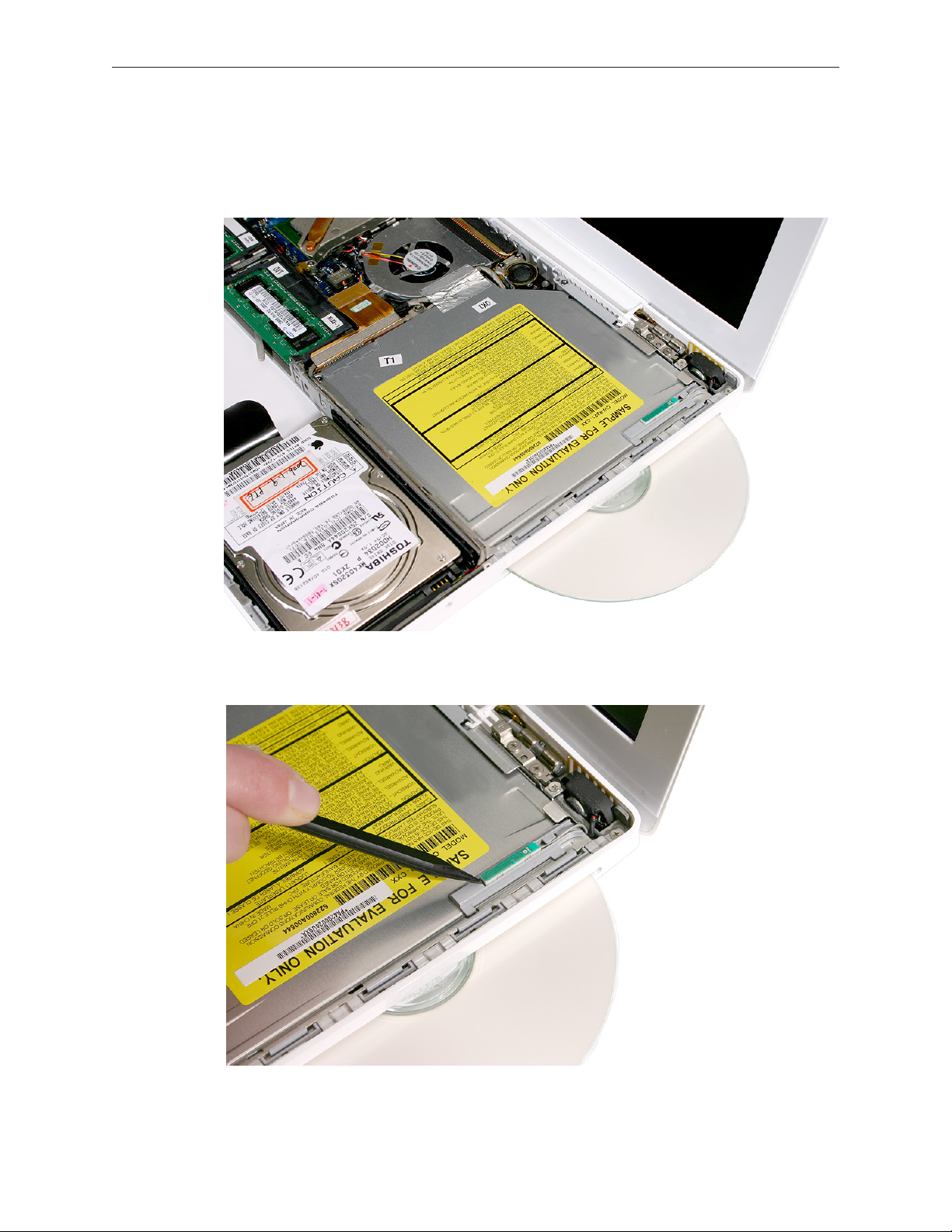
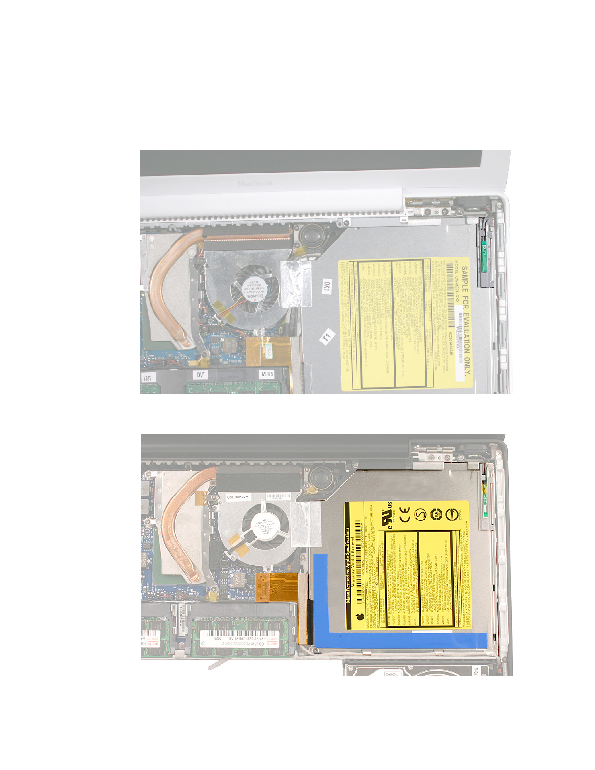
1. With the computer assembly on a clean, scratch-proof surface, locate the Bluetooth board
and holder. Note that the Bluetooth holder stays with the drive and is included with a
replacement optical drive.
Late 2006 Model:
MacBook (13-inch) Take Apart — Optical Drive 97
Page 98

2. Tilt up the Bluetooth board from the upper right corner of the optical drive.
3. Disconnect the optical drive ex cable from the logic board.
MacBook (13-inch) Take Apart — Optical Drive 98
Page 99
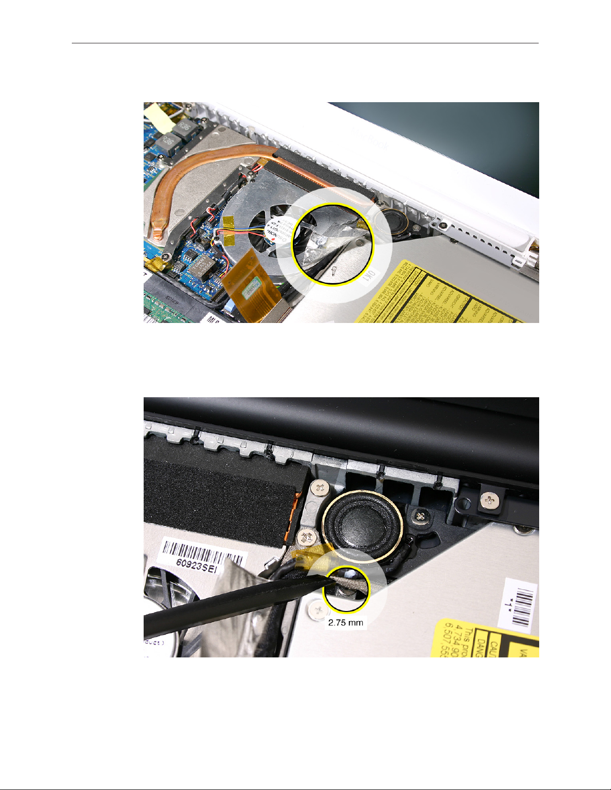
4. Peel up the tape from the optical drive.
5. Carefully lift up or move aside the cables to remove the single 2.75-mm long screw at the
mounting bracket. You might rst need to disconnect the ground screw by the speaker to
loosen the cables and access the mounting bracket screw.
MacBook (13-inch) Take Apart — Optical Drive 99
Page 100

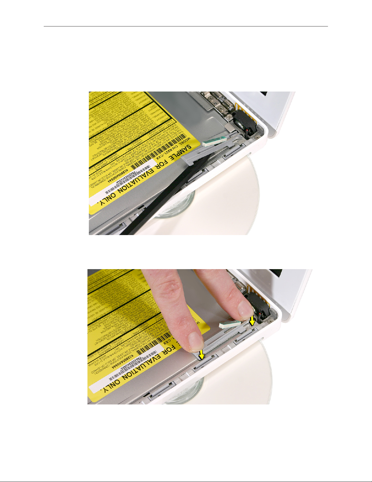
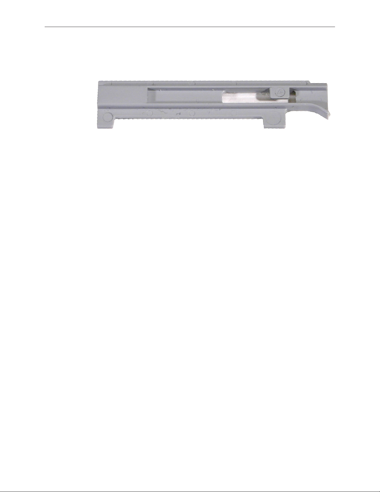
6. Use a black stick to slide the mounting bracket forward (away from the body of the drive and
toward the fan) to disengage it.
7. Slide out the hard drive, and set it aside.
MacBook (13-inch) Take Apart — Optical Drive 100
 Loading...