

Page 1
Service Source
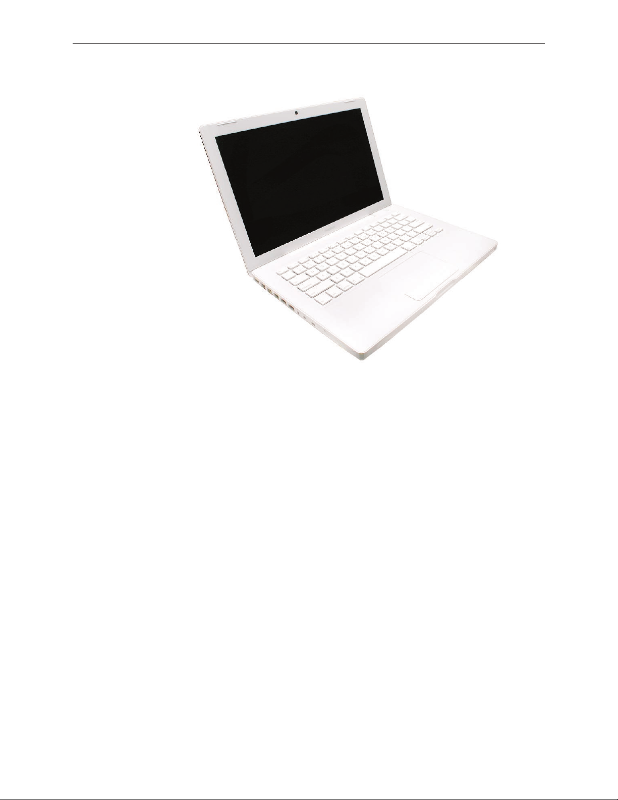
MacBook (13-inch)
16 May 2006
© 2006 Apple Computer, Inc. All rights reserved.
Page 2

MacBook (13-inch)
Contents
Take Apart
What’s New 6
Tools 8
Temperature Concerns 9
Note About Images in This Manual 9
Battery 10
RAM Door (L-Bracket) 13
Memory (DIMMs) 17
Removal Procedure 18
Replacement Procedure 20
Hard Drive 22
Top Case (with Keyboard) 25
AirPort Extreme Card 34
MagSafe DC-In Board 37
Left Speaker 41
Battery Connector with Sleep Switch 45
Hard Drive Connector 49
Fan 55
Heatsink 58
Applying Thermal Grease 61
Bluetooth Holder 64
Optical Drive 68
Optical Drive Cable 77
I/O Frame (with upper EMI shield) 80
Logic Board 83
ii
Page 3

Applying Thermal Grease 92
DIMM Lever Kit 96
Backup Battery 99
Bluetooth Antenna Board and Cable 102
Bluetooth Board 106
Bluetooth-to-Logic Board Cable 110
Subwoofer with Right Speaker Cable 115
Midframe 121
Display Bezel 126
Removal Procedure 127
Replacement Procedure 129
C-Channel 132
Clutch Block, Left 136
Clutch Block, Right 142
Clutch Caps 146
(Refer to “Clutch Block, Left” and “Clutch Block, Right”) 146
Bottom Case 147
Display Module 151
Clutch Cover 156
Bezel Scoops, Left and Right 161
LCD Panel 165
Antenna Receptors and Cables 168
LCD Panel Assembly 174
Removal Procedure 176
Reinstallation Procedure 180
Camera Assembly 187
LVDS Cable with USB Line 192
Microphone Cable 197
Inverter Board 203
iii
Page 4

Inverter Cable 206
Display Hinges, Left and Right 209
Bezel Brace, Left 212
Bezel Brace, Right 214
Sleep Magnet 218
Display Magnet Pairs 220
Display Rear Housing 224
Troubleshooting
General Information 228
Troubleshooting Steps 22
9
Symptom Charts 232
Block Diagram 23
7
Views
Views 240
Front: Keyboard and IR Window 240
Back: Air Vents and Display Clutch 241
Left Side: Ports 241
Right Side: Slot Drive 241
Battery Bay: Memory Card Levers and Hard Drive Pull Tab 242
Top Case Removed: Main Modules and Cable Routing 242
iv
Page 5
Service Source
Take Apart
MacBook (13-inch)
© 2006 Apple Computer, Inc. All rights reserved.
Page 6
What’s New
The MacBook (13-inch) portable computer is the rst computer of its size featuring the Intel Core
Duo processor and built-in iSight video camera. The main features and service dierences (from
similar-sized Apple portable computers) include:
Higher resolution 13.3-inch LCD panel
•
iSight camera built-in
•
Infrared sensor on front right corner
•
Hard drive is oered as a customer-replaceable module
•
Digital audio-in
•
MagSafe magnetic power connector
•
Supports extended desktop
•
Vertical-insert connectors—most of the cable connectors on the logic board use a new
•
design that requires “straight down” insertion and “straight up” extraction
Feet on the bottom case are heat-staked, so they are not removable
•
Built-in keyboard as part of top case
•
Operating temperature is hotter than previous models (refer to “Temperature Concerns” in
•
this chapter)
MacBook (13-inch) Take Apart 6
Page 7
The following table shows the MacBook (13-inch) model congurations at introduction:
Feature Good Better Best
Intel Core Duo processor 1.83 GHz 2.0 GHz 2.0 GHz
Memory 512 MB (x2) 512 MB (x2) 512 MB (x2)
Hard Drive 60 GB 60 GB 80 GB (120 GB)
Optical Drive Combo, 9.5 mm Super, 9.5 mm Super, 9.5 mm
Housing White White Black
Display 13.3-inch, 1280x800, 114 dpi, Low Reection Glossy Polarizer (LRGP)
Battery 55-Whr Lithium Polymer
Power Adapter 60 W, A70, MagSafe MPM
Keyboard integral to top case:
Product name on display bezel:
MacBook (13-inch) Take Apart 7
Page 8
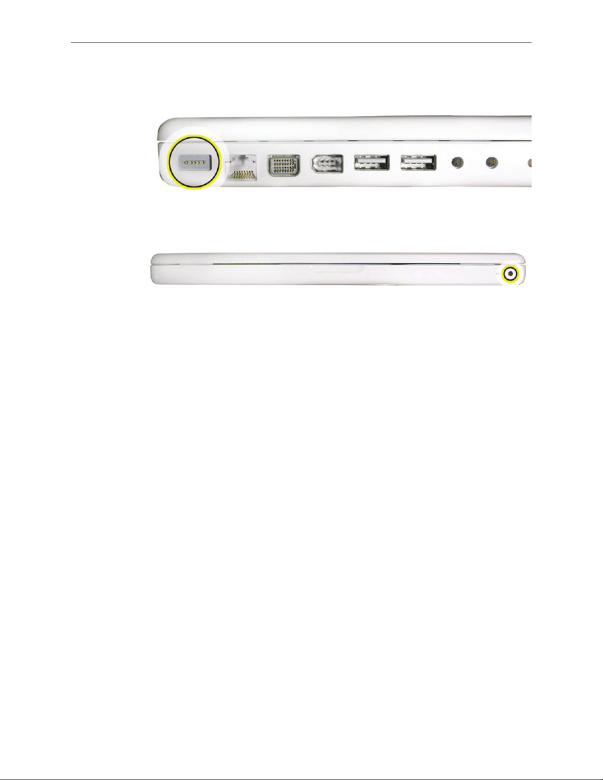
MagSafe power connector port:
Infrared window on front of computer:
For additional views of the computer, refer to the “Views” chapter at the end of this manual.
Tools
The tools required to service this computer include:
Clean, soft, lint-free cloth
•
Coin
•
ESD wrist strap and mat
•
Magnetic Phillips #0 screwdriver (preferably with a long handle)
•
Black stick (Apple probe tool, part number 922-5065) or other nonconductive nylon or plastic
•
atblade tool
Access card (Apple part number 922-7172) to open the top case
•
Jeweler’s atblade screwdriver
•
Needlenose pliers
•
Stack of books, weighted boxes, or other means of support for display while removing
•
screws from hinge
Thermal grease (Apple thermal compound syringe, part number 922-7144)
•
Alcohol wipes
•
Felt-tip pen (optional)
•
Standard size CD or DVD disc
•
Power Adapter
Warning: The power adapter for this computer is unique to this model. It uses an MPM 4-pin
adapter plug. Do not use this power adapter with any other portable computer. Power adapters
from earlier iBook or PowerBook computers are not compatible and will not t the MPM plug.
MacBook (13-inch) Take Apart 8
Page 9
Temperature Concerns
This computer runs hotter than previous models. However, the normal operating temperature
is well within national and international safety standards. Nevertheless, customers may be
concerned about the generated heat. To prevent an unneeded repair, you can compare a
customer’s computer to a running model, if available, at your repair site. For more information
on temperature concerns and customer perception, refer to Knowledge Base article 30612 “Apple
Notebooks: Operating Temperature.”
http://docs.info.apple.com/article.html?artnum=30612
Note About Images in This Manual
Because a pre-production model was used for most of the images shown in this manual, you may
notice small dierences in appearance between the image pictured and the computer you are
servicing. However, although the appearance diers, the steps and sequence are the same unless
noted.
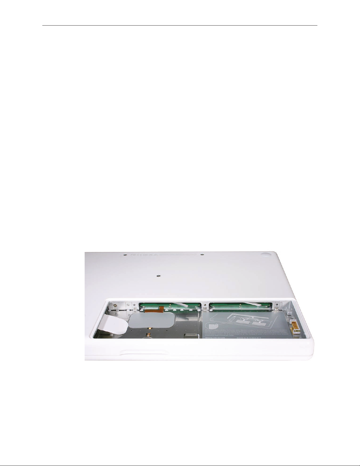
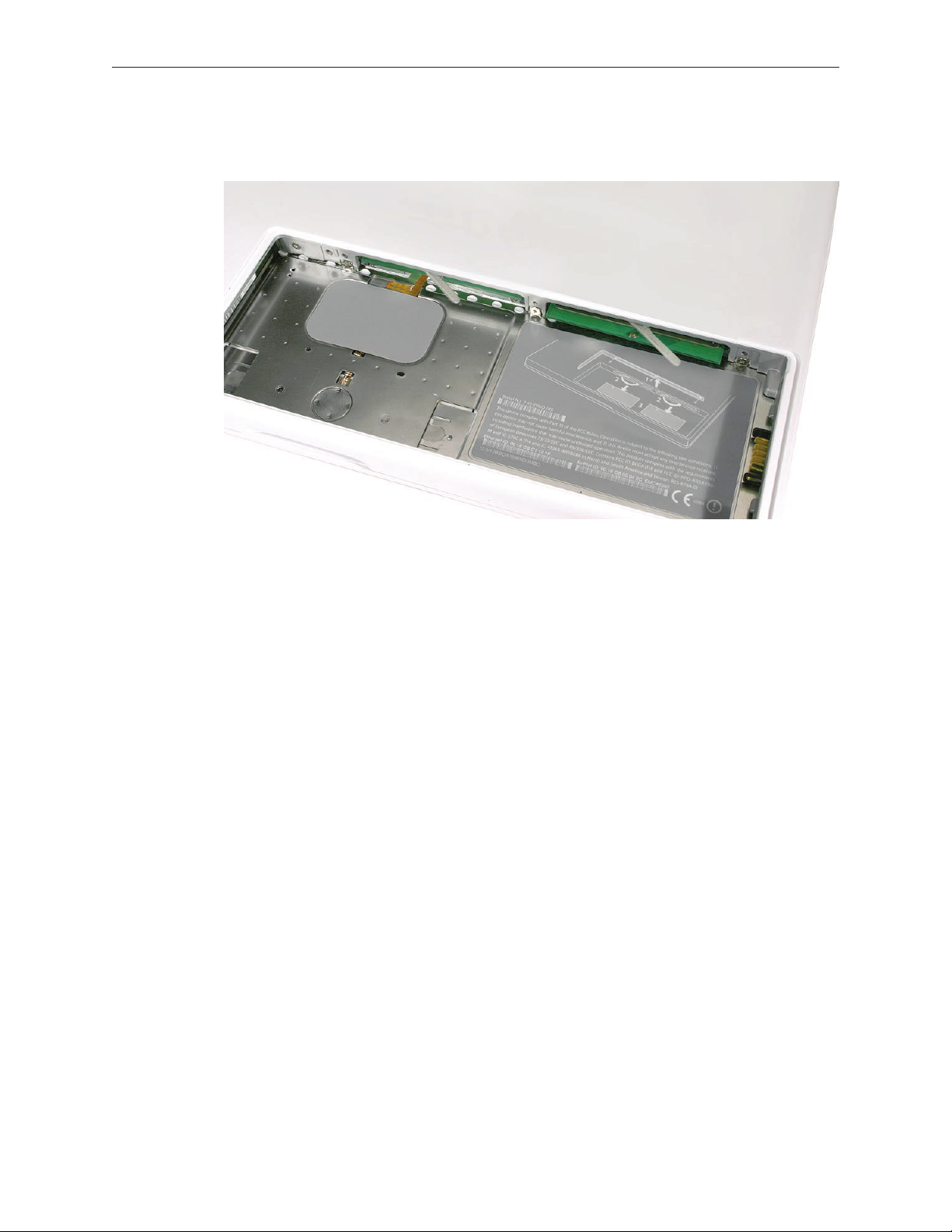
Memory Card Levers
Important: The following image shows the memory cards and hard drive installed in the battery
bay. Note the correct position of the memory card levers. Some images pictured in this manual
used a pre-production model, so the direction and appearance of the levers dier from the
accurate depiction below. Refer to the Views chapter for other useful reference images.
MacBook (13-inch) Take Apart 9
Page 10
Tools
Clean, soft, lint-free cloth
•
Coin
•
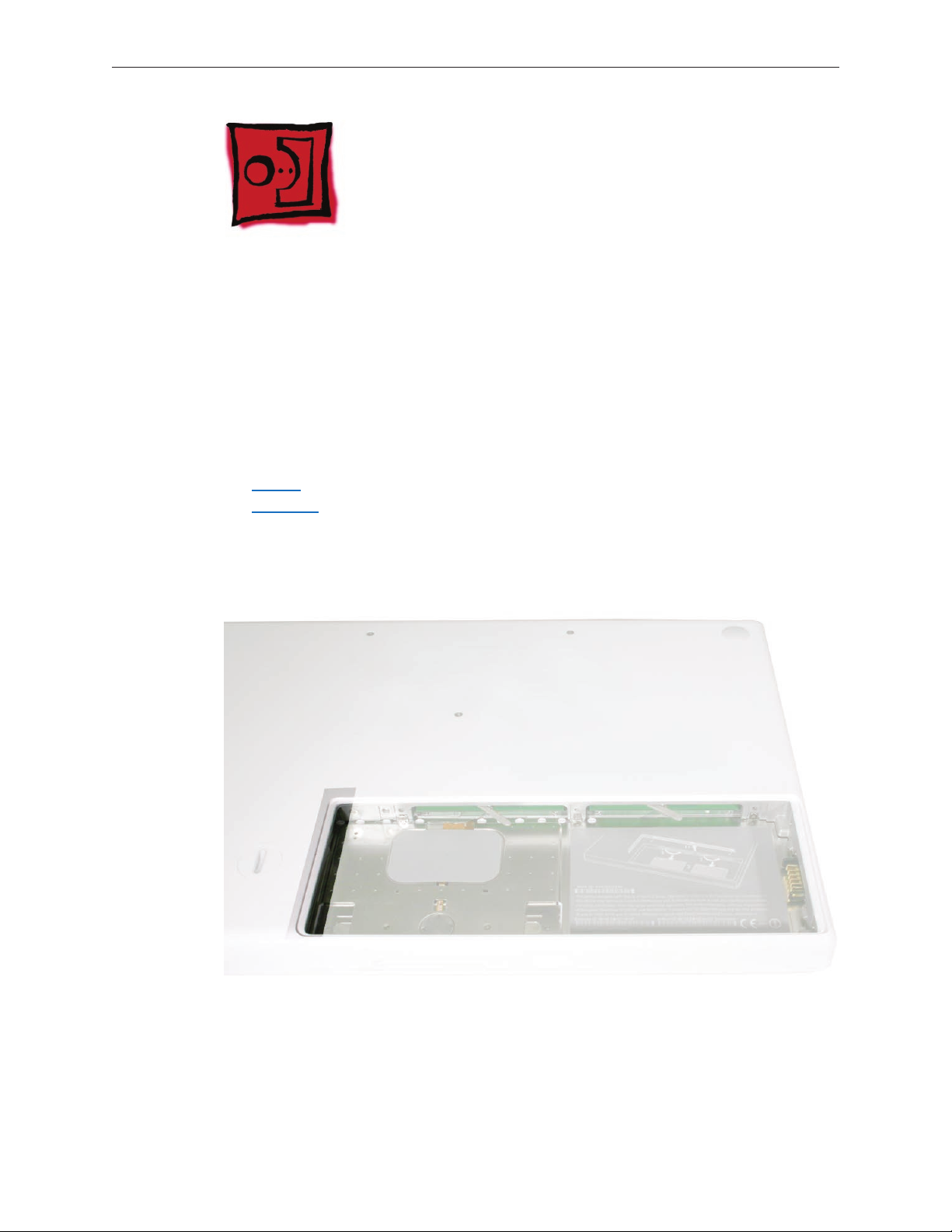
Part Location
Battery
Preliminary Steps
Warning: Always shut down the computer before opening it to avoid damaging the internal
components or causing injury. After you shut down the computer, the internal components can
be very hot. Let the computer cool down for 30 minutes before continuing
MacBook (13-inch) Take Apart 10
Page 11
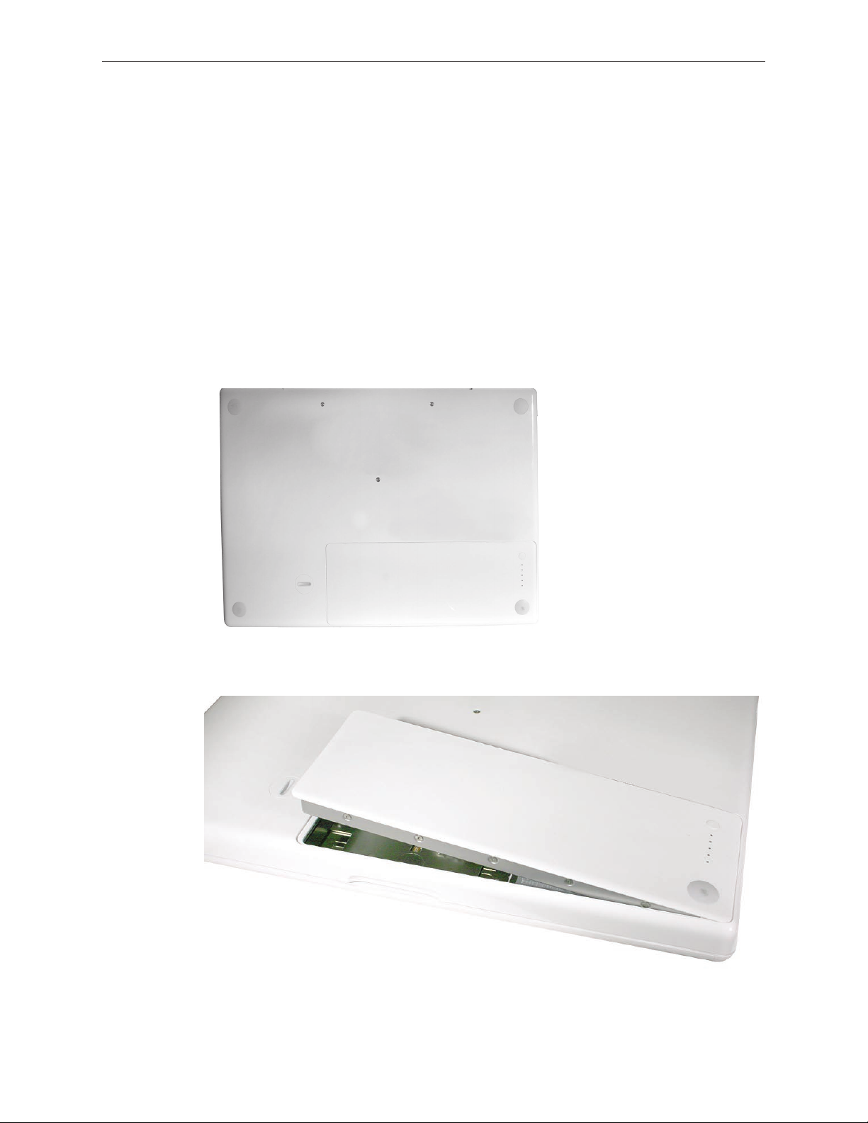
Procedure
Shut down the computer.
1.
Wait 30 minutes to allow the computer’s internal components to cool.
2.
Unplug all external cables from the computer except the power cord.
3.
Unplug the power cord.
4.
Put on an ESD wrist strap.
5.
Turn over the computer and place it on a soft cloth.
6.
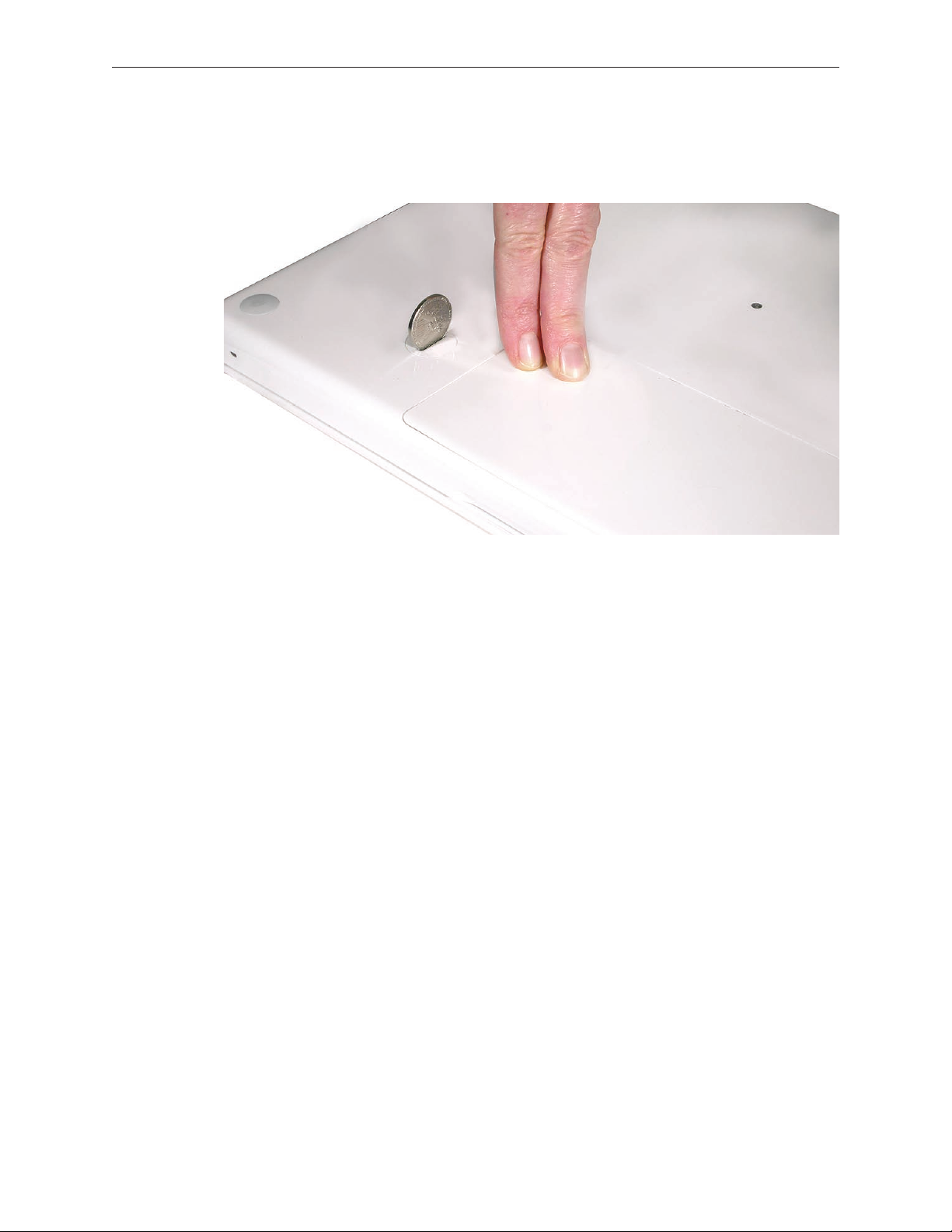
(image 0442A)
Use a coin to release the battery latch. Turn the coin a quarter turn clockwise to unlock the
7.
battery.
Lift out the battery from the battery bay.
8.
MacBook (13-inch) Take Apart 11
Page 12
To install the replacement battery, tilt the foot end of the battery into the battery bay rst.
9.
Then press and hold down the other end of the battery as you turn the coin to lock it into
place.
Reassemble and test the computer.
10.
MacBook (13-inch) Take Apart 12
Page 13
RAM Door (L-Bracket)
Tools
Soft cloth
•
ESD wrist strap and mat
•
Magnetic Phillips #0 screwdriver
•
Black stick (Apple part number 922-5065) or other nonconductive nylon or plastic atblade
•
tool
Part Location
Preliminary Steps
Before you begin, remove the battery.
MacBook (13-inch) Take Apart 13
Page 14
Procedure
With the computer closed and upside down on a soft cloth, touch a metal surface inside the
1.
battery bay to discharge any static electricity.
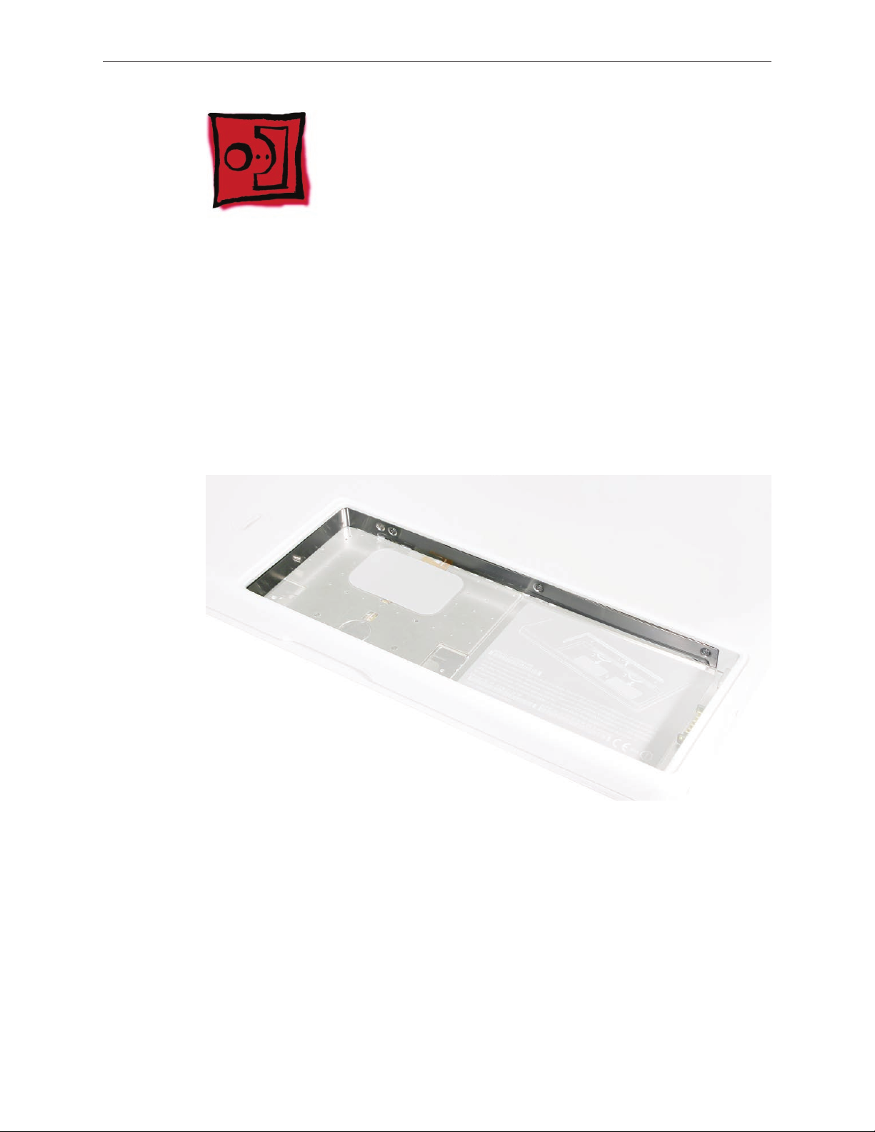
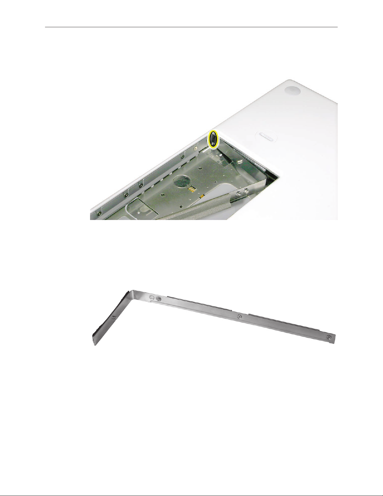
Loosen—but do not try to remove—the three captive screws along the RAM door.
2.
MacBook (13-inch) Take Apart 14
Page 15
Holding the long end of the L-shaped RAM door, pivot it out from the battery bay. (If
3.
necessary, use a black stick to tilt it up and out of the battery bay.) Be careful not to bend it.
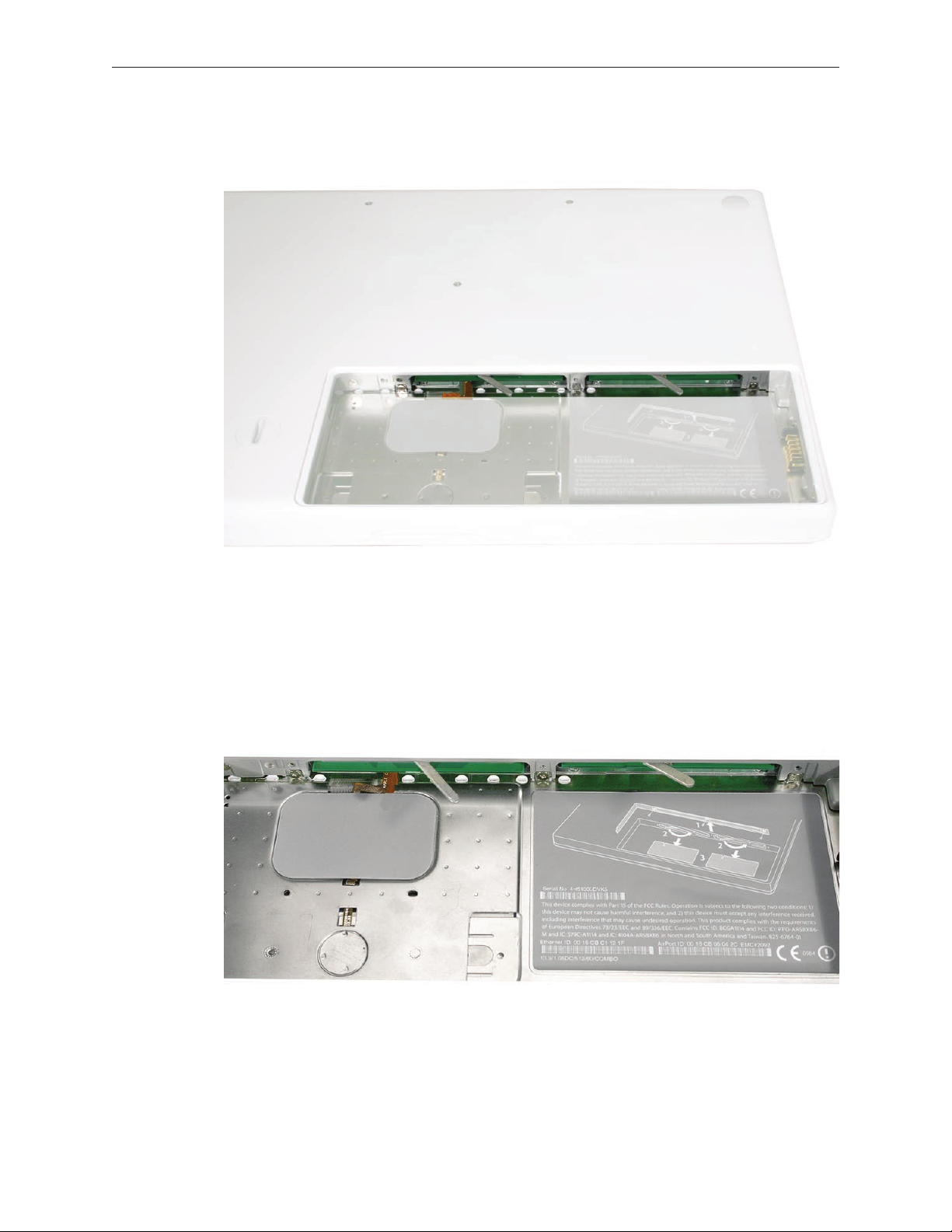
Replacement Note: Before replacing the RAM door, make sure that
• Hard drive pull tab is not exposed
• Cards are fully inserted
• Memory card levers are fully down before replacing the RAM door
Replacement Note: Check that the replacement RAM door has a rubber cushion to protect
the hard drive opening and two EMI gaskets to protect the memory card openings.
)
MacBook (13-inch) Take Apart 15
Page 16
Replacement Note: Install the replacement RAM door by rst aligning the short end at the
4.
notch near the hard drive opening.
Replacement Note: Use a black stick, if necessary, to tuck in the EMI gaskets so they do not
protrude from the edge of the battery bay. Make sure the three screws align with the holes
in the bottom case before tightening them.
Reassemble and test the computer.
5.
MacBook (13-inch) Take Apart 16
Page 17

Memory (DIMMs)
This computer comes with a minimum of 512 MB of 667 GHz Double Data Rate 2 (DDR2)
Synchronous Dynamic Random-Access Memory (SDRAM) installed. It has two slots that can
accept SDRAM Small Outline Dual Inline Memory Modules (SO-DIMMs). The slots are side-by-side
on the logic board behind the RAM door. For best performance, memory should be installed
as pairs with an equal memory card in each slot. The maximum amount of memory for this
computer is 2 GB, with 1GB DIMM installed in each slot.
Memory cards must meet these requirements:
1.25 inch or smaller
•
256 MB, 512 MB, or 1 GB
•
200-pin
•
PC-5300 DDR2 667 MHz Type RAM
•
Tools
ESD wrist strap and mat
•
Preliminary Steps
Before you begin, remove
Battery
•
RAM door
•
MacBook (13-inch) Take Apart 17
Page 18
Part Location
Removal Procedure
Touch a metal surface inside the battery bay to discharge any static electricity.
1.
Put on an ESD wrist strap.
2.
To eject the memory cards from the slots, move the levers all the way to the left.
3.
MacBook (13-inch) Take Apart 18
Page 19
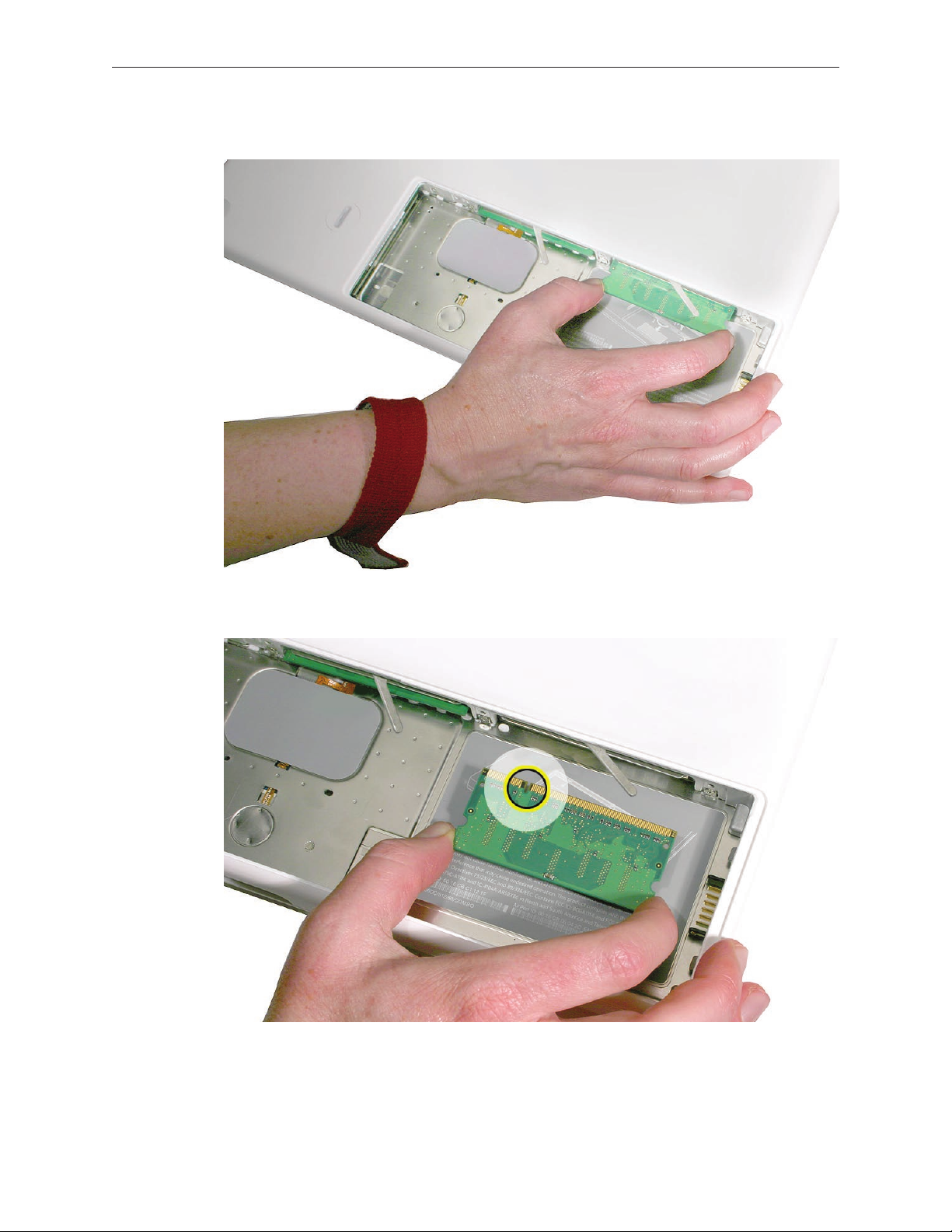
Holding the memory cards by the corners, slide them out from the battery bay.
4.
Important: Do not touch the gold connectors. Handle the card only by its edges.
MacBook (13-inch) Take Apart 19
Page 20
Replacement Procedure
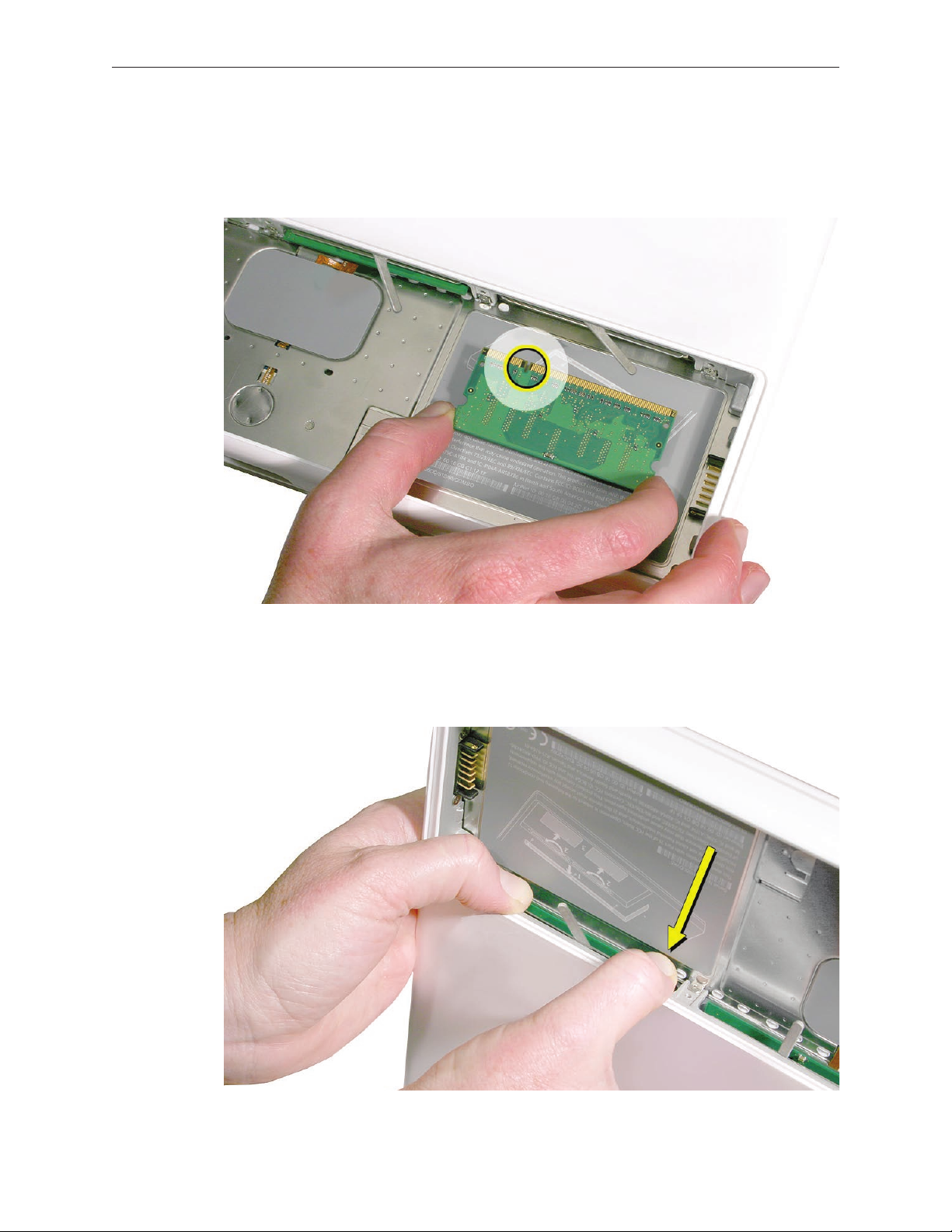
Align the memory card so that the gold connectors face the slot and the notch is on the left.
1.
(The chip side of the board faces down.)
Use two ngers to push rmly on the edge of the memory cards. If there is a tight t,
2.
installing the cards may take some force to ensure that they are fully inserted.
MacBook (13-inch) Take Apart 20
Page 21
Important: When the cards are fully inserted, the edges of the cards are hidden, as shown by
the recessed card on the left in the image below.
If the levers do not return to the closed position, move them to close them.
3.
Reassemble and test the computer.
4.
Make sure the computer recognizes the new memory by opening System Proler, clicking
5.
More Info, and clicking Memory.
MacBook (13-inch) Take Apart 21
Page 22
Hard Drive
Tools
ESD wrist strap and mat
•
Black stick (Apple part number 922-5065) or other nonconductive nylon or plastic atblade
•
tool
Preliminary Steps
Before you begin, remove
Battery
•
RAM door
•
Part Location
MacBook (13-inch) Take Apart 22
Page 23
Procedure
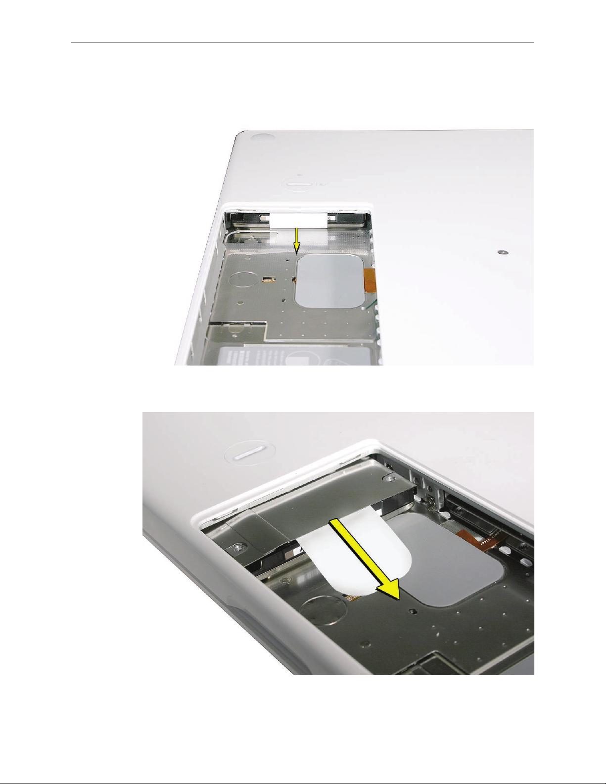
If the hard drive pull-tab is tucked in, use a black stick to unroll it.
1.
Pull the tab straight out to slide the drive out from the rubber rails in the battery bay.
2.
MacBook (13-inch) Take Apart 23
Page 24
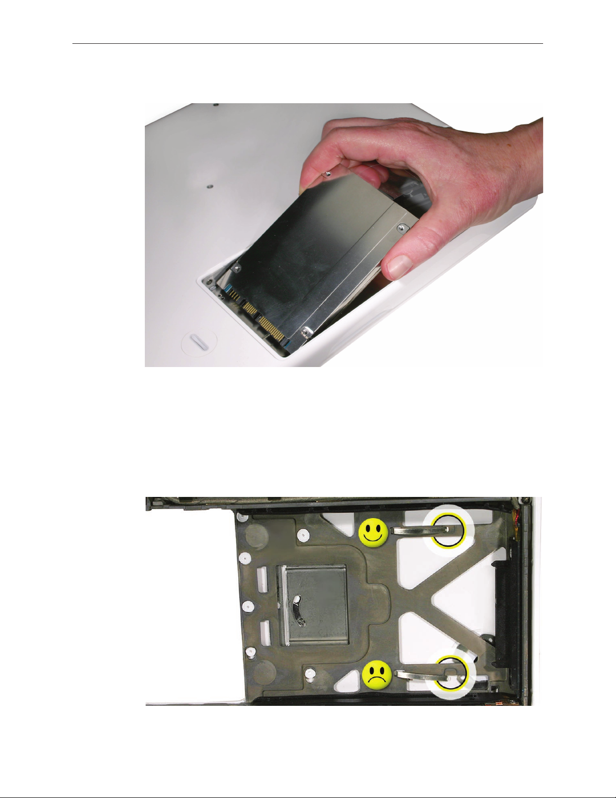
Hold the drive only by the sides when removing and replacing it.
3.
Install the replacement hard drive, and reassemble and test the computer.
4.
Important: After a new hard drive replacement, you must update the operating system to
Mac OS X version 10.4.6 or later.
Replacement Note: If you are installing the hard drive while the top case is o, make sure
the two bottom case spring guides are aligned with the notches in the bottom case. The
image below shows the top spring centered and the bottom spring o center.
MacBook (13-inch) Take Apart 24
Page 25
Top Case (with Keyboard)
Tools
ESD wrist strap and mat
•
Magnetic Phillips #0 screwdriver (preferably with a long handle)
•
Black stick (Apple part number 922-5065) or other nonconductive nylon or plastic atblade
•
tool
Access card (Apple part number 922-7172) to open the top case
•
Clean, soft, lint-free cloth
•
Preliminary Steps
Before you begin, remove
Battery
•
RAM door
•
Part Location
MacBook (13-inch) Take Apart 25
Page 26
Procedure
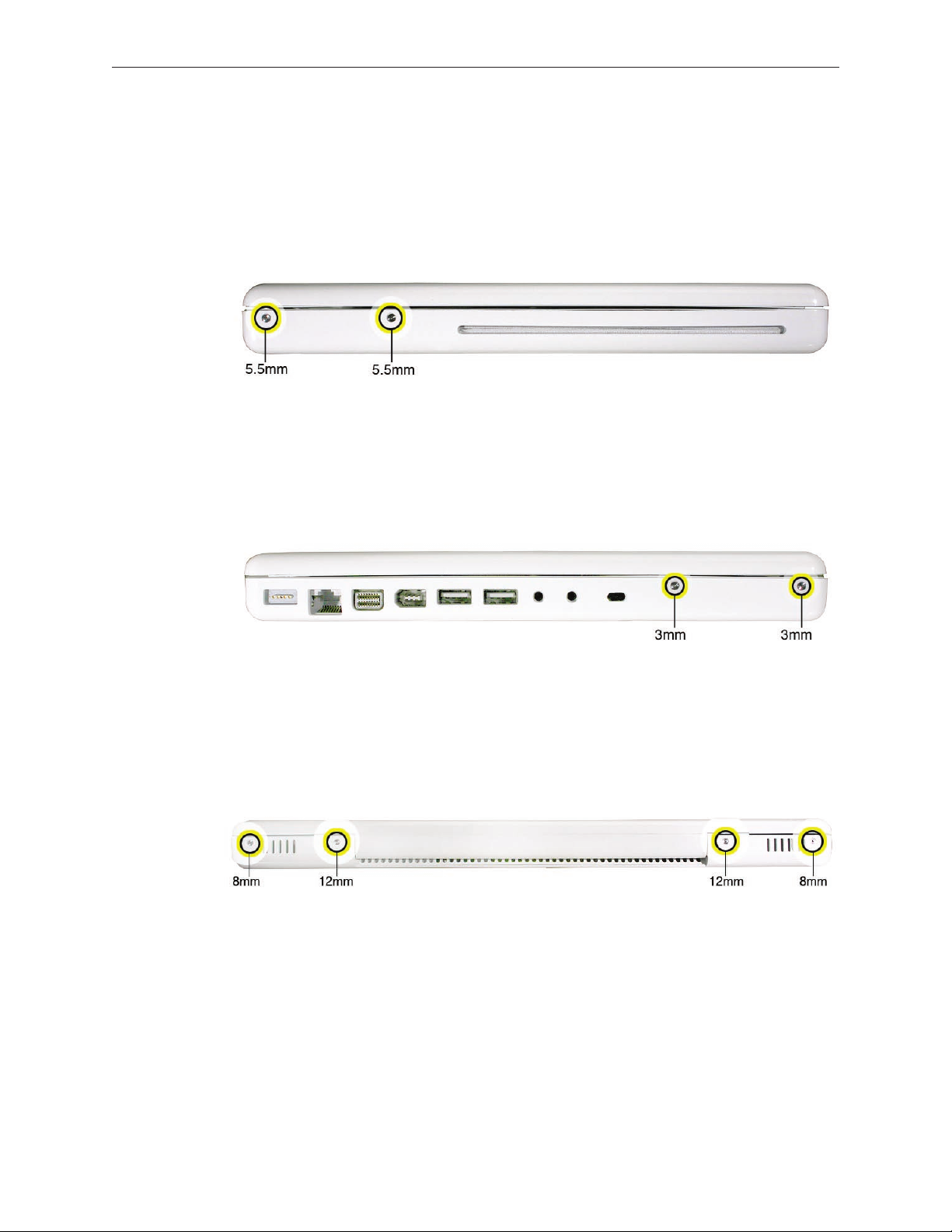
With the computer upright, remove the two identical 5.5-mm long shoulder screws from the
1.
right side of the computer.
Replacement Caution: When installing these top case screws, do not press on the area over
the slot drive. The slot-drive bezel could be damaged with too much pressure.
Important: Notice the two screws at the left side of the computer. Although they can be
2.
removed, they exist for cosmetic purposes only and do not require removal. If they are
removed, however, be sure to reinstall the two identical 3-mm long shoulder screws at
the corner near the ports. Do not use longer screws.
(image 0434A)
At the back of the computer, remove the four #0 Phillips screws (two at each side) near the
3.
display hinge--
• Two 12-mm long shoulder screws that are closest to the hinge
• Two 8-mm long shoulder screws at the back corners of the compute
MacBook (13-inch) Take Apart 26
Page 27
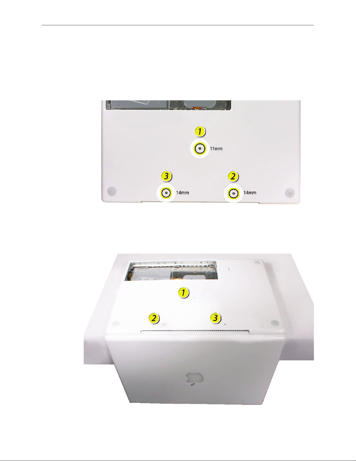
Turn over the computer, and on the outside of the bottom case, remove the three #0 Phillips
4.
screws:
• Two 14-mm long screws near display hinge
• One 11-mm long at center of bottom case
Replacement Caution: Do not put one of the longer screws in the center screw hole or it
will damage the logic board.
Replacement Caution: When installing the three bottom case screws, the LCD panel can be
damaged if the display is closed. Make sure you open the display to a 90-degree angle and
place the display upside down over a cloth-draped table edge so that the display and
keyboard are protected. Then install the screws in the order shown.
MacBook (13-inch) Take Apart 27
Page 28
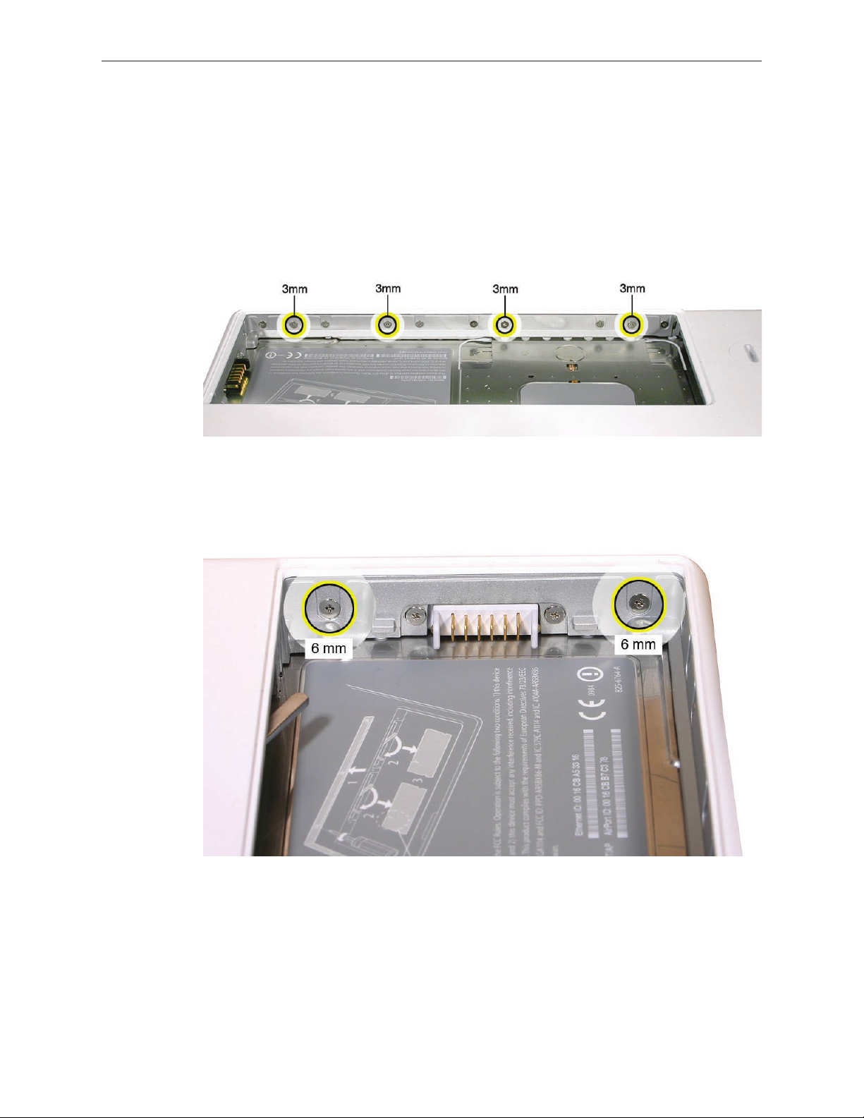
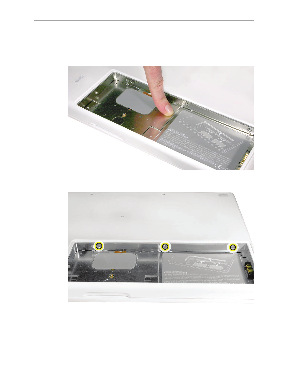
Notice the long row of #0 Phillips screws at the front edge of the battery bay.
5.
Important: Remove only the four screws shown. Remove the 3-mm long identical screws as
6.
follows:
Starting at the corner closest to the battery connector, skip the rst screw, then remove the
second, fourth, seventh, and ninth screw.
Tip: To help remember the screw sequence, think of it as “2, 4, 7, 9 loosens the top case every
time.”
In the battery bay, remove the two 6-mm long identical screws that are on both outer sides
7.
of the battery connector. Do not remove the two screws that are closest to the battery
connector.
MacBook (13-inch) Take Apart 28
Page 29
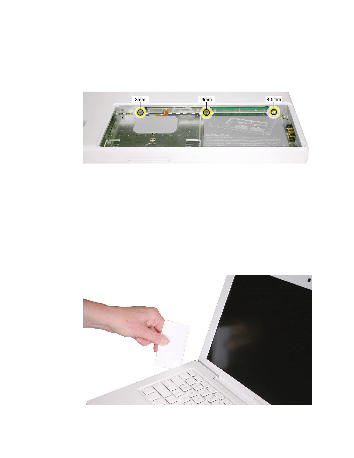
In the battery bay, use a long-handled screwdriver to remove the three screws at the inner
8.
edge of the battery bay near where the RAM slots are located:
• Two identical 3-mm long screws
• One longer 4.5-mm long screw at the corner of the battery bay nearest the battery
connector
Because this is a recessed area, the screwdriver has to go in at an angle. Keep the screwdriver
in line with the screw head as much as possible.
Replacement Caution: When installing these three screws, an incorrect installation could
cause the reassembled computer to wobble in use. To prevent a wobble symptom, use light
pressure to hold the top case onto the assembly when installing the screws.
Open the display to a 90-degree angle or wider.
9.
Warning: Inserting a tool too far or performing this step too quickly could break some of the
10.
snaps that secure the top case. Be especially careful with the left front corner of the top case.
Starting at the left corner and working in a counter-clockwise direction, use an access card
tool to open the gap along the front of the top case, around the perimeter, and to the right
side above the optical drive slot.
MacBook (13-inch) Take Apart 29
Page 30
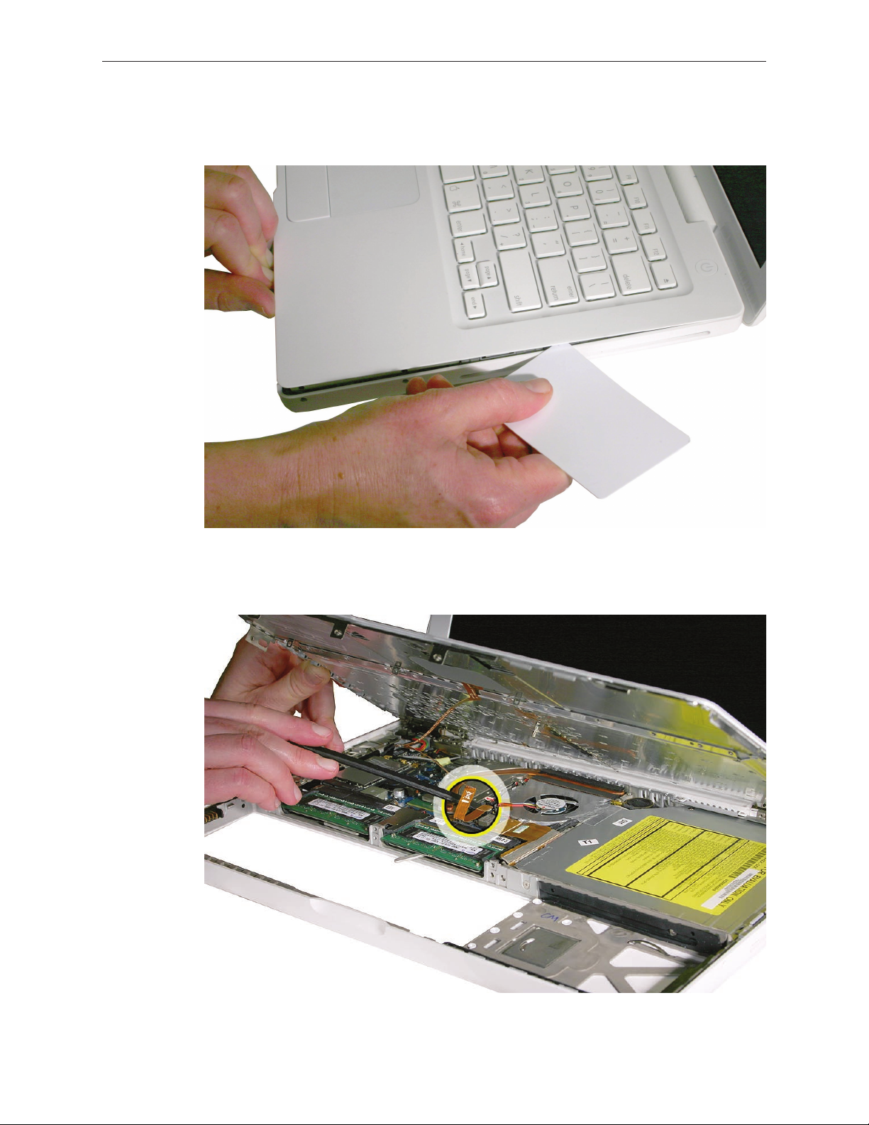
With the top and right side gap opened, tilt up—but do not remove—the right edge of the
11.
top case. This motion releases the remaining snaps between the top case and bottom case.
Raise up the top case so you can see where the folded trackpad ex cable attaches to the
12.
logic board.
MacBook (13-inch) Take Apart 30
Page 31

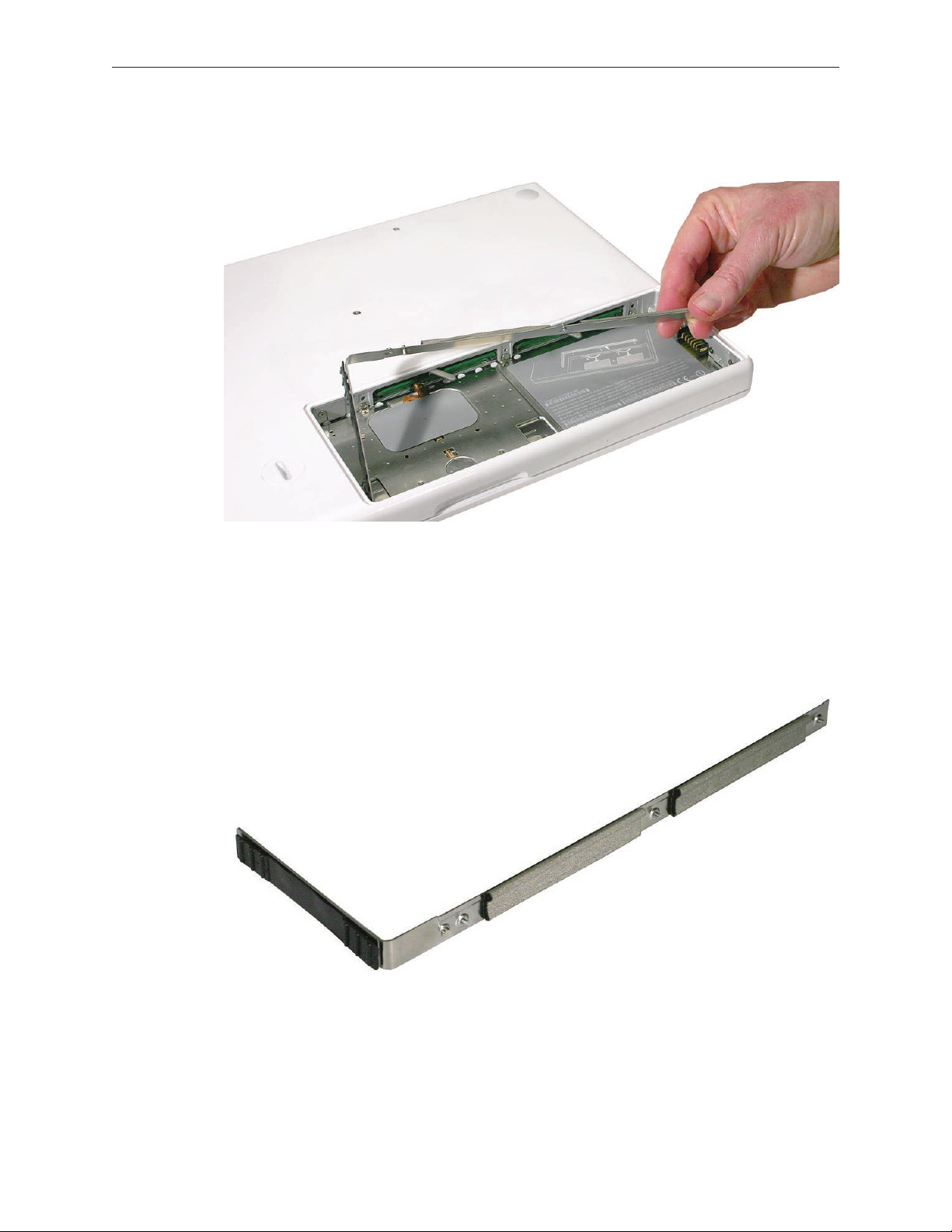
Use the at end of a black stick to reach in and disconnect the trackpad cable.
13.
Lift the top case up and away from the computer assembly.
14.
MacBook (13-inch) Take Apart 31
Page 32

Refer to the following notes to install the replacement top case, and reassemble and test the
15.
computer.
Replacement Note: The top case includes heatstaked keyboard, webbing, EMI shield, a small
rectangular foam pad, and attached trackpad cable.
Replacement Note: Before replacing the top case, make sure to connect the trackpad ex
cable to the logic board.
MacBook (13-inch) Take Apart 32
Page 33

Replacement Note: Install the right side of the top case rst (near the disc slot). Then
starting from the right, secure the snaps by pressing along the outer edge of the top case in
a clockwise direction around the front and left side of the top case.
Replacement Caution: When installing the exterior screws and the battery bay screws, apply
light pressure to the top case to ensure that the top case ts to the bottom case without any
gaps.
Replacement Caution: If any of the four bezel clips at the slot-load bezel come loose, simply
insert them back in the slots. Make sure they are in place while reassembling the computer
and before installing the top case.
MacBook (13-inch) Take Apart 33
Page 34

AirPort Extreme Card
Tools
ESD wrist strap and mat
•
Black stick (Apple part number 922-5065) or other nonconductive nylon or plastic atblade
•
tool
Magnetic Phillips #0 screwdriver
•
Preliminary Steps
Before you begin, remove
Battery
•
RAM door
•
Top case with keyboard
•
Part Location
MacBook (13-inch) Take Apart 34
Page 35

Procedure
Remove the 8.5-mm long screw (that also functions as the left speaker cable ground pin)
1.
from the upper right corner of the board. (The thick head on this screw helps identify it.)
Remove the 3-mm long screw from the upper left corner of the board.
2.
Pull the card up slightly and out of the card socket on the logic board.
3.
MacBook (13-inch) Take Apart 35
Page 36

Disconnect the two cables from the AirPort Card. Note that the black cable is on the left and
4.
the gray cable is on the right.
Tip: To remember the cable locations, think “Left = bLack; Right = gRay.”
Install the replacement AirPort Card, and reassemble and test the computer.
5.
Replacement Note: With the cables replaced on the AirPort Card, be sure that a strip of tape
is used where shown to keep the cables away from the EMI nger and the two capacitors
near the heatsink.
MacBook (13-inch) Take Apart 36
Page 37

MagSafe DC-In Board
Tools
ESD wrist strap and mat
•
Magnetic Phillips #0 screwdriver
•
Black stick (Apple part number 922-5065) or other nonconductive nylon or plastic atblade
•
tool
Preliminary Steps
Before you begin, remove
Battery
•
RAM door
•
Top case with keyboard
•
Part Location
MacBook (13-inch) Take Apart 37
Page 38

Procedure
Place a black stick under the DC-in connector cables to help disconnect the connector, then
1.
pull the connector away from its connection on the logic board.
Remove the 3-mm long screw from the MagSafe DC-in board.
2.
Caution: The DC-in port is magnetic. Be careful that it doesn’t pick up screws or other small
parts.
MacBook (13-inch) Take Apart 38
Page 39

From the port side, use a black stick to help tilt up the MagSafe DC-in board and remove it
3.
from the logic board.
Replacement Note: Make sure the folded side of the EMI shield ts over the I/O frame rib so
that the rib is sandwiched between the anges of the EMI shield.
Replacement Note: If installing a new MagSafe DC-in board, rst peel o the protective
membrane from the MagSafe DC-in board. Then connect the DC-in cable to the connector
on the logic board, and insert the board into the upper left corner of the bottom case. Finally,
install the screw.
MacBook (13-inch) Take Apart 39
Page 40

Install the replacement MagSafe DC-in board, and reassemble and test the computer.
4.
Replacement Note: Check that there are no bent EMI ngers on the shield covering the port
area.
Replacement Note: Check the port side of the bottom case to make sure the MagSafe DC-in
port is level with the port opening.
MacBook (13-inch) Take Apart 40
Page 41

Left Speaker
Tools
ESD wrist strap and mat
•
Magnetic Phillips #0 screwdriver
•
Black stick (Apple part number 922-5065) or other nonconductive nylon or plastic atblade
•
tool
Preliminary Steps
Before you begin, remove
Battery
•
RAM door
•
Top case with keyboard
•
Part Location
MacBook (13-inch) Take Apart 41
Page 42

Procedure
Disconnect the speaker cable from the logic board.
1.
Remove the 5.5-mm long speaker screw near the left display hinge.
2.
Route the cable underneath the AirPort cables.
3.
MacBook (13-inch) Take Apart 42
Page 43

Remove the 6-mm long speaker screw.
4.
Pull up on the speaker cable to remove it from the frame.
5.
Pivot up the speaker from the left corner.
6.
MacBook (13-inch) Take Apart 43
Page 44

Route the speaker cable underneath the DC-in cable.
7.
Install the replacement speaker cable, and reassemble and test the computer.
8.
MacBook (13-inch) Take Apart 44
Page 45

Battery Connector with Sleep Switch
Tools
ESD wrist strap and mat
•
Magnetic Phillips #0 screwdriver
•
Black stick (Apple part number 922-5065) or other nonconductive nylon or plastic atblade
•
tool
Preliminary Steps
Before you begin, remove
Battery
•
RAM door
•
Top case with keyboard
•
Part Location
MacBook (13-inch) Take Apart 45
Page 46

Procedure
Caution: Do not touch the raised section of the sleep switch connector. It is fragile and could
break.
Remove the two 4.5-mm long shoulder screws from the frame at the battery connector.
1.
Replacement Caution: Make sure the screws are the proper length. A longer screw could
damage the board.
MacBook (13-inch) Take Apart 46
Page 47

Tilt up the battery connector end of the board.
2.
Caution: Do not touch the raised section of the sleep switch connector. It is fragile and could
3.
break. Using a black stick, insert it under the cables, and lift up the connector from the logic
board.
MacBook (13-inch) Take Apart 47
Page 48

Replacement Note: To avoid bending the pins on the sleep switch connector card, make
sure you squarely align the pins over the logic board and keep the connector card level
when installing it. Install the “pins” end of the sleep switch connector rst; then install the
battery connector and screws.
Install the replacement battery connector with sleep switch, and reassemble and test the
4.
computer.
MacBook (13-inch) Take Apart 48
Page 49

Hard Drive Connector
Tools
ESD wrist strap and mat
•
Magnetic Phillips #0 screwdriver
•
Black stick (Apple part number 922-5065) or other nonconductive nylon or plastic atblade
•
tool)
Preliminary Steps
Before you begin, remove
Battery
•
RAM door
•
Hard drive
•
Top case with keyboard
•
Part Location
MacBook (13-inch) Take Apart 49
Page 50

Procedure
Remove the two 6-mm long screws from the hard drive connector at the right front side of
1.
the computer.
Carefully lift up the hard drive connector from the bottom case. This action automatically
2.
disconnects the hard drive board from the sleep LED/IR receiver ex cable.
MacBook (13-inch) Take Apart 50
Page 51

Replacement Caution: Note the tiny connector at the end of the hard drive board. It
connects to the sleep LED/ IR receiver board at the front right corner of the computer via a
tiny ex cable. To reinstall the ex cable, rst peel up the end of the snubber to access the
length of the ex cable. Carefully peel up the ex cable from its adhesive. Using a black stick,
tilt up the tiny ex cable at the right corner. Insert it into the connector on the hard drive
board, and fold down the tiny locking lever on the connector. Without straining the
connection, carefully tilt the hard drive board into place in front of the snubber.
MacBook (13-inch) Take Apart 51
Page 52

Pull up the hard drive connector cable that runs along the bottom edge of the optical drive.
3.
Note the three cable routing guides when reinstalling the cable.
Use the two pull tabs to disconnect the optical drive ex cable and the LVDS cable.
4.
MacBook (13-inch) Take Apart 52
Page 53

Use the pull tab to disconnect the hard drive connector cable.
5.
Route the hard drive connector cable under the black cables.
6.
MacBook (13-inch) Take Apart 53
Page 54

Install the replacement hard drive connector, and reassemble and test the computer.7.
MacBook (13-inch) Take Apart 54
Page 55

Fan
Tools
ESD wrist strap and mat
•
Magnetic Phillips #0 screwdriver
•
Black stick (Apple part number 922-5065) or other nonconductive nylon or plastic atblade
•
tool
Preliminary Steps
Before you begin, remove
Battery
•
RAM door
•
Top case with keyboard
•
Part Location
MacBook (13-inch) Take Apart 55
Page 56

Procedure
Peel up the strip of tape that overlaps the fan near the optical drive.
1.
Remove the screws from the fan:
2.
• 6-mm long screw from the upper left (this acts as a ground pin for the speaker,
microphone, and LVDS cables)
• 3-mm long screw from the upper right (normally hidden underneath the cable bundles)
MacBook (13-inch) Take Apart 56
Page 57

Tilt up the fan and disconnect the fan cable from the logic board.
3.
Holding the fan tilted up from the bottom case, peel away the adhesive foam that overlaps
4.
the fan and the heatsink.
Replacement Note: Because the foam strip tears easily, be sure to install a new strip of
adhesive foam before reassembling the computer.
Install the replacement fan, and reassemble and test the computer.
5.
Replacement Note: Make sure the cables are fully tucked in the channel between the fan
and the optical drive. Reapply the tape or apply new tape.
MacBook (13-inch) Take Apart 57
Page 58

Heatsink
Tools
ESD wrist strap and mat
•
Magnetic Phillips #0 screwdriver
•
Black stick (Apple part number 922-5065) or other nonconductive nylon or plastic atblade
•
tool
Alcohol wipes
•
Thermal grease syringe (Apple part number 922-7144)
•
Felt-tip pen (optional)
•
Preliminary Steps
Before you begin, remove
Battery
•
RAM door
•
Top case with keyboard
•
Fan
•
Part Location
MacBook (13-inch) Take Apart 58
Page 59

Procedure
Remove the four identical 8-mm long screws from the heatsink.
1.
Note that the screw at the lower right corner anchors a exible ground tab for the speaker
cable that runs along the top of the RAM card carriers. Make sure the tab is sandwiched
between the heatsink and the screw when it is reinstalled.
MacBook (13-inch) Take Apart 59
Page 60

Starting at the lower bracket of the heatsink, start to tilt it up to loosen it from the logic
2.
board.
Holding the heatsink by its edges, tilt it up and disconnect the two thermistor connectors
3.
from the logic board.
Important: Anytime the heatsink is removed (even if it is to replace another module), apply
4.
new thermal grease as described in the following section.
MacBook (13-inch) Take Apart 60
Page 61

Applying Thermal Grease
Warning: Whenever the heatsink is separated from the logic board (even if you are
installing the same heatsink or board), the thermal grease must be completely removed and
replaced. Failure to do so can cause the computer to overheat and be damaged.
With the heatsink removed, use a black stick to remove as much thermal grease as possible
1.
from the two chips on the logic board and the two pads on the heatsink.
Use an alcohol wipe to completely clean the residual thermal grease from the two chips. (If
2.
you are replacing the logic board with a new one, skip this step.)
Important: Use extreme care not to damage the logic board components.
MacBook (13-inch) Take Apart 61
Page 62

Use an alcohol wipe to completely clean the two pads on the heatsink.
3.
Using the syringe, put a 0.15 to 0.175 cc dab of thermal grease, in the center, on the mating
4.
surfaces of both chips, as shown below.
Important: One syringe (922-7144) contains 0.3 to 0.35 cubic centimeters (cc) of thermal
grease. That is enough for 0.15 to 0.175 cc of grease for each chip. Use half of the syringe
contents per chip. You might nd it helpful to use a felt-tip pen to mark the half-way point
on the syringe before applying the rst dab. Then you can empty the rest of the syringe
contents on the remaining chip. Although the amount shown appears to be plenty of grease,
this is the correct amount that has been tested and veried on the production line.
Important: Avoid unnecessary contact with new thermal material, as dirt and body oils
reduce the material’s conductivity.
MacBook (13-inch) Take Apart 62
Page 63

While centering the heatsink pads over the two chips, lower the heatsink onto the logic
5.
board and press on the areas where the screw brackets on the heatsink meet the standos
on the board. Make sure the heatsink is level on the board before installing the screws.
Install the heatsink, and reassemble and test the computer.
6.
MacBook (13-inch) Take Apart 63
Page 64

Bluetooth Holder
Important: The Bluetooth holder is included with a replacement optical drive and should not be
removed unless it is damaged or no longer sticks to the optical drive housing.
Tools
ESD wrist strap and mat
•
Any standard size CD or DVD disc
•
Black stick (Apple part number 922-5065) or other nonconductive nylon or plastic atblade
•
tool
Preliminary Steps
Before you begin, remove
Battery
•
RAM door
•
Top case with keyboard
•
Part Location
MacBook (13-inch) Take Apart 64
Page 65

Procedure
Insert a CD or DVD disc half way into the slot drive to help support the drive and prevent
1.
damage.
Use a black stick to slide out the Bluetooth board from its holder.
2.
MacBook (13-inch) Take Apart 65
Page 66

Warning: To prevent damage to the optical drive, do not touch or press anywhere else
3.
on the drive.
Use a black stick to carefully pry up the Bluetooth holder from the top of the optical drive.
4.
Make sure you use as little pressure as possible to prevent damage to the drive.
Replacement Note: Peel o the adhesive backing from the Bluetooth holder and apply it to
the drive where shown. Press the holder lightly to make sure it adheres to the drive.
MacBook (13-inch) Take Apart 66
Page 67

Install the replacement Bluetooth holder, remove the optical drive disc, and reassemble and
5.
test the computer.
MacBook (13-inch) Take Apart 67
Page 68

Optical Drive
Tools
ESD wrist strap and mat
•
Magnetic Phillips #0 screwdriver
•
Black stick (Apple part number 922-5065) or other nonconductive nylon or plastic atblade
•
tool
Preliminary Steps
Before you begin, remove
Battery
•
RAM door
•
Top case with keyboard
•
Part Location
MacBook (13-inch) Take Apart 68
Page 69

Procedure
With the computer assembly on a clean, scratch-proof surface, locate the Bluetooth board
1.
and holder.
Tilt up the Bluetooth board from the upper right corner of the optical drive.
2.
MacBook (13-inch) Take Apart 69
Page 70

Remove the 6-mm long ground screw near the optical drive ex cable connector. Loosen the
3.
cable that runs along the tabs at the lower edge of the optical drive.
Disconnect the optical drive ex cable from the logic board.
4.
MacBook (13-inch) Take Apart 70
Page 71

Peel up the tape from the optical drive. Carefully lift up the cables without disconnecting
5.
them.
Without straining the cables, use the pointed end of a black stick to move aside (but do not
6.
disconnect) the LVDS cable at the upper left corner of the optical drive so you can access the
screw and bracket under the cable. Remove the 3.5-mm long screw.
MacBook (13-inch) Take Apart 71
Page 72

7.
Use a black stick to slide the bracket forward (away from the body of the drive and toward
the fan) to disengage it.
Slide out the hard drive, and set it aside.
8.
MacBook (13-inch) Take Apart 72
Page 73

Access the two identical 3-mm long screws along the bottom edge of the drive at the hard
9.
drive snubber. (If the snubber is blocking one of the screws, carefully peel up the snubber.)
Lift up the cable that runs between the drive and the snubber at the lower edge of the
10.
optical drive.
Warning: Handle the optical drive at the side edges only. Do not touch or press
11.
anywhere else on the drive.
MacBook (13-inch) Take Apart 73
Page 74

Grasp the optical drive ex cable and use it as a pull tab as you tilt up the optical drive. Be
12.
careful where it can catch on cables.
Replacement Note: Make sure the bracket on the optical drive is pushed in before placing
the optical drive in the bottom case.
Replacement Note: Reverse the screw order: install snubber screws rst.
Replacement Note: If you are installing a replacement drive, make sure it includes the
following:
• Bluetooth holder
• Sliding bracket and two screws
• Cable guide rail
MacBook (13-inch) Take Apart 74
Page 75

Replacement Note: If you are installing a replacement drive, check that the sliding bracket
that is secured with two screws slides easily and is not too tight. If it is too tight, loosen the
screws just enough so the bracket slides with ease.
Note: For correct cable routing, refer to the image below:
MacBook (13-inch) Take Apart 75
Page 76

Before installing the optical drive, make sure the cables on the bottom case are routed as
13.
shown.
Install the replacement optical drive and reassemble and test the computer.
14.
Important: For best performance after a new optical drive replacement, be sure to update
the operating system to Mac OS X version 10.4.6 or later.
MacBook (13-inch) Take Apart 76
Page 77

Optical Drive Cable
Tools
ESD wrist strap and mat
•
Black stick (Apple part number 922-5065) or other nonconductive nylon or plastic atblade
•
tool
Preliminary Steps
Before you begin, remove
Battery
•
RAM door
•
Top case with keyboard
•
Optical drive
•
Part Location
MacBook (13-inch) Take Apart 77
Page 78

Procedure
Warning: Handle the optical drive at the side edges only. Do not touch or press anywhere
else on the drive.
With the optical drive on a clean, scratch-proof surface, use a black stick to evenly pry up the
1.
cable connector from the drive.
Remove the optical drive cable.
2.
MacBook (13-inch) Take Apart 78
Page 79

Install the replacement optical drive cable, and reassemble and test the computer.
3.
Note that both sides of the cable have an adhesive mesh strip.
MacBook (13-inch) Take Apart 79
Page 80

I/O Frame (with upper EMI shield)
Tools
ESD wrist strap and mat
•
Magnetic Phillips #0 screwdriver
•
Black stick (Apple part number 922-5065) or other nonconductive nylon or plastic atblade
•
tool
Preliminary Steps
Before you begin, remove
Battery
•
RAM door
•
Memory cards
•
Top case with keyboard
•
MagSafe DC-in board and
•
AirPort Card
•
Left speaker
•
Part Location
MacBook (13-inch) Take Apart 80
Page 81

Procedure
At the left side of the computer assembly, remove the screws from the I/O frame:
1.
• Two identical 7.5-mm long screws (one at each end)
• One 9.5-mm long screw in the middle
Tilt up the I/O frame to remove it from the computer assembly.
2.
MacBook (13-inch) Take Apart 81
Page 82

Note that the I/O frame includes the EMI shield. Be careful not to bend the shield as you
remove or install it.
Install the replacement I/O frame, and reassemble and test the display.3.
MacBook (13-inch) Take Apart 82
Page 83

Logic Board
Tools
ESD wrist strap and mat
•
Magnetic Phillips #0 screwdriver
•
Black stick (Apple part number 922-5065) or other nonconductive nylon or plastic atblade
•
tool
Alcohol wipes
•
Thermal grease (Apple part number 922-7144)
•
Felt-tip pen (optional)
•
Preliminary Steps
Before you begin, remove
Battery
•
RAM door
•
Memory cards
•
Top case with keyboard
•
AirPort Extreme Card
•
MagSafe DC-in board and cable
•
I/O frame with upper EMI shield
•
Fan
•
Heatsink
•
MacBook (13-inch) Take Apart 83
Page 84

Part Location
Procedure
Disconnect the optical drive ex cable from the logic board. 1.
MacBook (13-inch) Take Apart 84
Page 85

Without straining the optical drive ex cable, note the position of the LVDS cable beneath it.
2.
Pull the pull-tab to disconnect the LVDS cable from the logic board.
Pull the pull-tab on the hard drive cable connector to disconnect it from the logic board.
3.
MacBook (13-inch) Take Apart 85
Page 86

Lift up the LVDS cable to locate the Bluetooth antenna cable at the edge of the logic board,
4.
and disconnect the Bluetooth antenna cable.
Remove the 3-mm long screw next to the lower end of the midframe.
5.
MacBook (13-inch) Take Apart 86
Page 87

Disconnect the inverter cable and microphone cable from the logic board.
6.
From the lower left corner of the logic board, use a black stick to raise up and disconnect the
7.
sleep switch connector.
Pull up the microphone cable and remove the 3-mm long screw between the memory slots.
8.
MacBook (13-inch) Take Apart 87
Page 88

Remove the 3-mm long screw from the upper right area of the board. Disconnect the
9.
inverter cable.
Move aside the cables.
10.
MacBook (13-inch) Take Apart 88
Page 89

Holding the logic board by its right side, tilt it up and with a small rocking motion, remove it
11.
at an angle away from the I/O ports. You might nd it helpful to use a black stick between
the side of the bottom housing and the ports.
Replacement Note: When replacing the logic board, make sure all cables are kept clear of
the board, and the I/O shield is securely positioned along the ports. Use a black stick to
slightly ex the port side of the bottom case to install the logic board.
MacBook (13-inch) Take Apart 89
Page 90

If you are installing a new logic board, transfer the following parts to the replacement board:
12.
• Backup battery on the underside of the logic board (Refer to Backup Battery in this
chapter)
• Tape at the edge of the board between the inverter connector and the large chip
• AirPort Extreme Card
• Memory cards
• I/O shield
MacBook (13-inch) Take Apart 90
Page 91

Before installing the logic board, make sure the gold-colored spring located beneath the
13.
inverter cable connector is intact (not bent or broken).
Before installing the logic board, check the locator pins on the bottom case. Make sure the
14.
two openings in the logic board t over the locator pins.
MacBook (13-inch) Take Apart 91
Page 92

Install the replacement logic board, and reassemble and test the computer.
15.
Applying Thermal Grease
Warning: Whenever the logic board is separated from the heatsink (even if you are installing
the same board or heatsink), the thermal grease must be completely removed and replaced.
Failure to do so can cause the computer to overheat and be damaged.
With the logic board installed in the bottom case and the heatsink removed, use a black stick
1.
to remove as much thermal grease as possible from the two chips on the logic board and
the two pads on the heatsink.
MacBook (13-inch) Take Apart 92
Page 93

Use an alcohol wipe to completely clean the residual thermal grease from the two chips.
2.
Important: Use extreme care not to damage the logic board components.
Use an alcohol wipe to completely clean the two pads on the heatsink.
3.
MacBook (13-inch) Take Apart 93
Page 94

Using the syringe, put a 0.15 to 0.175 cc dab of thermal grease, in the center, on the mating
4.
surfaces of both chips, as shown below.
Important: One syringe (922-7144) contains 0.3 to 0.35 cubic centimeters (cc) of thermal
grease. That is enough for 0.15 to 0.175 cc of grease for each chip. Use half of the syringe
contents per chip. You might nd it helpful to use a felt-tip pen to mark the half-way point
on the syringe before applying the rst dab. Then you can empty the rest of the syringe
contents on the remaining chip. Although the amount shown appears to be plenty of grease,
this is the correct amount that has been tested and veried on the production line.
Important: Avoid unnecessary contact with new thermal material, as dirt and body oils
reduce the material’s conductivity.
MacBook (13-inch) Take Apart 94
Page 95

While centering the heatsink pads over the two chips, lower the heatsink onto the logic
5.
board and press on the areas where the screw brackets on the heatsink meet the standos
on the board. Make sure the heatsink is level on the board before installing the screws.
MacBook (13-inch) Take Apart 95
Page 96

DIMM Lever Kit
Tools
•
ESD wrist strap and mat
•
Magnetic Phillips #0 screwdriver
•
Black stick (Apple part number 922-5065) or other nonconductive nylon or plastic atblade
tool
Preliminary Steps
Before you begin, remove
•
Battery
•
RAM door
•
Memory cards
•
Top case with keyboard
•
AirPort Extreme Card
•
MagSafe DC-in board and cable
•
I/O frame with upper EMI shield
•
Fan
•
Heatsink
•
Logic Board
Part Location
MacBook (13-inch) Take Apart 96
Page 97

Procedure
Important: The following image shows the memory cards and hard drive installed in the battery
bay. Note the correct position of the memory card levers.
Caution: The remaining images pictured in this procedure used a pre-production model, so the
direction and appearance of the levers dier from the computer that you are servicing. However,
the steps should be the same.
On the underside of the logic board, use light pressure with a Phillips screwdriver to remove
1.
the 3-mm long lever screw. (Remove both screws if replacing both levers.)
MacBook (13-inch) Take Apart 97
Page 98

Lift o the lever.
2.
Before installing the replacement lever and spring, note that the underside of the lever has a
3.
hook end on the spring. The hook must wrap around the slightly raised pin on the memory
card carrier.
Install the replacement lever, spring, and screw, and check that the lever moves correctly.
4.
Reassemble and test the computer.
Replacement Note: The lever kit includes two levers, two springs, and two screws.
MacBook (13-inch) Take Apart 98
Page 99

Backup Battery
Tools
ESD wrist strap and mat
•
Black stick (Apple part number 922-5065) or other nonconductive nylon or plastic atblade
•
tool
Before you begin, remove
Battery
•
RAM door
•
Memory cards
•
Top case with keyboard
•
AirPort Extreme Card
•
MagSafe DC-in board and cable
•
I/O frame with upper EMI shield
•
Fan
•
Heatsink
•
Logic board
•
Part Location
MacBook (13-inch) Take Apart 99
Page 100

Procedure
On the underside of the logic board, note the position of the backup battery, attached cable,
1.
and tape.
Using your ngers or a black stick, carefully peel up the backup battery from the adhesive on
2.
the logic board.
MacBook (13-inch) Take Apart 100
 Loading...