

Page 1

K
Service Source
Apple Color OneScanner/B
Page 2

K
Service Source
Specifications
Color OneScanner/B
Page 3

Specifications Characteristics - 1
Characteristics
Scanner T ype
Maximum Document Size
Speed
Grayscale
Dropout Color
Interface
Flatbed
8.5 by 14 in.
13 ms/line at 300 dpi
256 levels (8 bits per pixel)
White
SCSI
Page 4

Specifications Electrical - 2
Electrical
Line Voltage
Frequency
120 VAC ±10% (US and Canada)
100/120/200/220/240 VAC ± 10% (Universal)
58–62 Hz (US and Canada)
48–62 Hz (Universal)
Page 5

Specifications Physical - 3
Physical
Size
Weight
Height: 4.3 in. (110 mm)
Width: 13.4 in. (340 mm)
Depth: 21.5 in. (545 mm)
23 lb. (10.45 kg)
Page 6

Specifications Environmental - 4
Environmental
Operating Temperature
Storage Temperature
Relative Humidity
50–104°F (10–40°C)
–40 to 117°F (–40 to 47°C)
20–95% noncondensing
Page 7

K
Service Source
Troubleshooting
Color OneScanner/B
Page 8

Troubleshooting General/ - 1
General
The Symptom Charts included in this chapter will help you
diagnose specific symptoms related to your product. Because cures
are listed on the charts in the order of most likely solution, try
the first cure first. Verify whether or not the product continues to
exhibit the symptom. If the symptom persists, try the next cure.
(Note: If you have replaced a module, reinstall the original module
before you proceed to the next cure.)
If you are not sure what the problem is, or if the Symptom Charts
do not resolve the problem, refer to the Flowchart for the product
family.
For additional assistance, contact Apple Technical Support.
Page 9

Troubleshooting Symptom Charts /LED Error Messages - 2
Symptom Charts
LED Error Messages
LED blinks once Replace logic board.
LED blinks twice 1 Clean glass cover assembly.
2 Check lamp holder connector.
3 Check that label of fluorescent lamp faces down into lamp
holder.
4 Replace lamp.
5 Replace optical assembly.
Page 10

Troubleshooting Symptom Charts /LED Error Messages - 3
LED blinks three
times
Power-on self test
does not find error
(LED does not blink);
scanner is not
capturing image
correctly
1 Check motor carrier assembly.
2 Check drive belt assembly.
3 Check gears and pulleys.
4 Check limit switch assembly.
5 Check home position switch assembly.
6 Check carrier shaft; it should not be bent.
Replace optical assembly.
Page 11

Troubleshooting Symptom Charts /Miscellaneous - 4
Miscellaneous
Power lamp not on;
machine dead
Optical assembly does
not move
1 Plug in power cord.
2 Close lamp cover and turn button clockwise.
3 Check interlock switch with multimeter. Replace switch if it
is not opening and closing.
4 Check fuse FU1 on power supply board.
5 Replace logic board.
6 Replace power supply.
1 Check SCSI connection.
2 Check SCSI ID.
3 Check and clean or replace belt.
4 Check belt tension. Belt should be tight with no slack.
5 Check for damage to gears or buildup of foreign material.
Clean or replace gears.
Page 12

Troubleshooting Symptom Charts/Miscellaneous - 5
Optical assembly moves
once and then does not
move
Scanning program
crashes during middle of
scanning operation, or
computer hangs
1 Check limit switch for continuity.
2 Check drive belt.
3 Check drive belt pulleys.
4 Check carrier motor.
1 Verify version of scanner application software.
2 Verify that scanner driver is present.
3 Verify version of scanner driver.
4 Check SCSI connection.
5 Verify that host computer has enough memory.
6 Verify that system software is version 7.0 or above.
7 Verify SCSI ID of scanner.
8 Verify scanner SCSI termination.
9 Turn on scanner and reboot computer.
10 Replace logic board.
Page 13

Troubleshooting Symptom Charts/Miscellaneous - 6
Fluorescent lamp won’t
light or is dim
Scan command does not
execute
1 Check lamp holder connector.
2 Check that label of fluorescent lamp faces down into lamp
holder.
3 Replace lamp.
4 Replace optical assembly.
5 Replace logic board.
1 Check external cable connections.
2 Reset SCSI select switch on scanner to unused device
number. Scanner is factory-preset at 2. Do not use 7, 8,
9, or 0.
3 Check that SCSI cable terminates correctly.
4 Replace logic board.
Page 14

Troubleshooting Symptom Charts /Miscellaneous - 7
Image not clean; dark
or light spots
Scanning performed,
but image doesn’t
reach host computer
Incorrect image on
host screen
1 Clean glass with water and soft, lint-free cloth.
2 Adjust contrast or threshold settings on application.
3 Replace lamp.
4 Replace optical assembly.
5 Replace logic board.
1 Check interface connector.
2 Replace optical assembly.
3 Check fuse FU1 on logic board.
4 Replace logic board.
1 Clean glass with water and soft, lint-free cloth.
2 Replace optical assembly.
Page 15

K
Service Source
T ak e Apart
Color OneScanner/B
Page 16
Take Apart Top Cover - 1
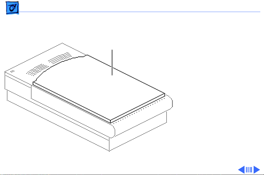
Top Cover
Top Cover
No preliminary steps are
required before you begin
this procedure.
Page 17
Take Apart Top Cover - 2
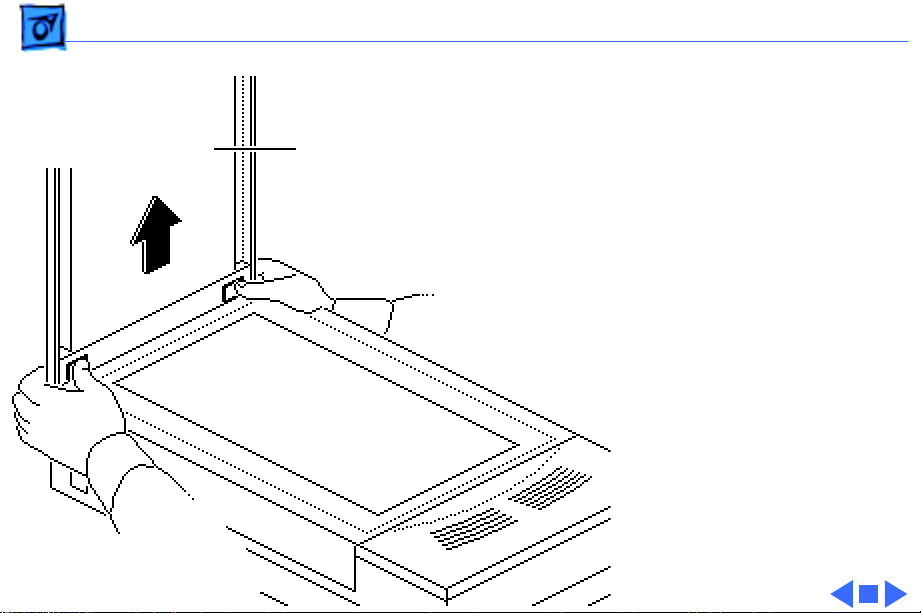
Press the clips and lift the
top cover.
Top Cover
Page 18
Take Apart Glass Cover Assembly - 3
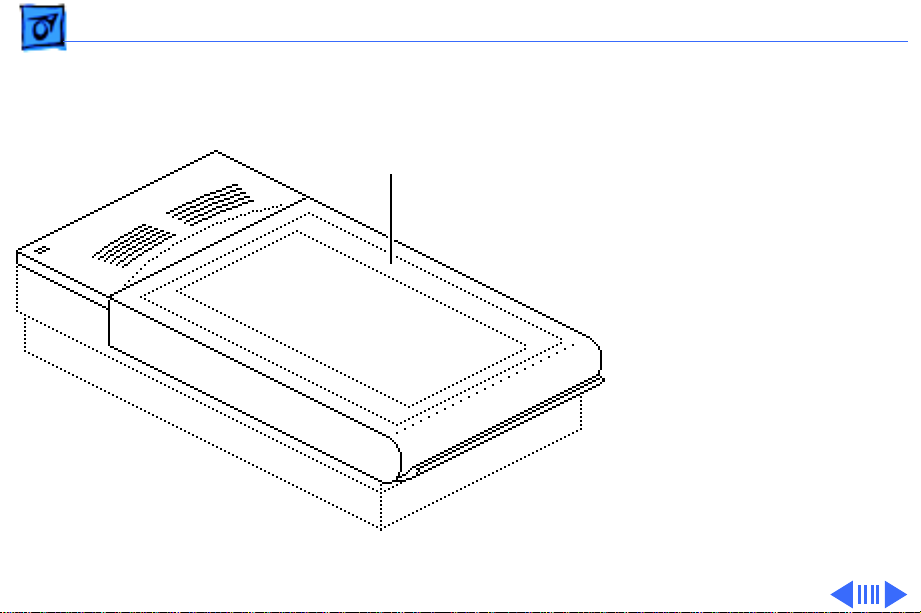
Glass Cover
Glass Cover
Assembly
Assembly
Before you begin, remove
the top cover.
Caution:
precautions in Bulletins/
Safety.
Review the ESD
Page 19
Take Apart Glass Cover Assembly - 4
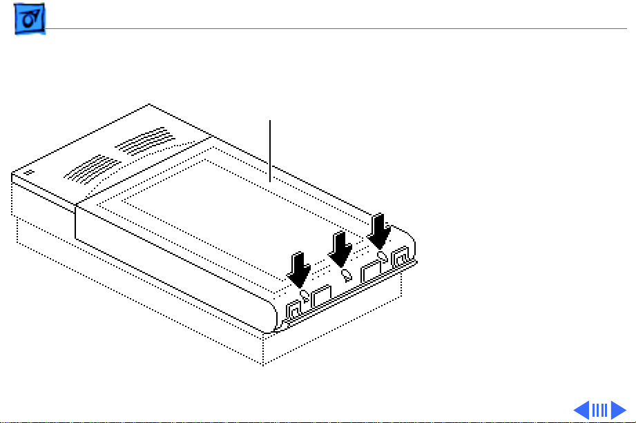
1 Loosen the three captive
screws.
Glass Cover
Assembly
Page 20

Take Apart Glass Cover Assembly - 5
2 Lift the glass cover
Glass Cover
Assembly
assembly from the rear,
and at the same time
press in and release the
two retaining clips.
Retaining Clips
(both sides)
Page 21

Take Apart Glass Cover Assembly - 6
Start Scan
Board
Scan Switch Cable
Glass Cover
Assembly
Caution:
When
removing the glass cover
assembly, make sure you
don’t damage the start
scan board.
3 Raise the glass cover
assembly to 90° and
disconnect the scan
switch cable from the
start scan board.
4 Remove the glass cover
assembly.
Page 22

Take Apart Glass Cover Assembly - 7
5
Replacement Note:
Before returning a
damaged glass cover
assembly, remove the
start scan board. Install
the start scan board on
the new glass cover
assembly.
Start Scan
Board
Page 23

Take Apart Scan Start Board - 8
Scan Start Board
Scan Start Board
Before you begin, remove
the following:
• Top cover
• Glass cover assembly
Caution:
precautions in Bulletins/
Safety.
Review the ESD
Page 24

Take Apart Scan Start Board - 9
1 Remove the two screws
and remove the scan
start board.
2 Remove the LED lenses.
Scan Start
Board
LED Lenses
Page 25

Take Apart Lid Hinge Assembly - 10
Lid Hinge Assembly
Before you begin, remove
the following:
• Top cover
• Glass cover assembly
Lid Hinge
Assembly
Caution:
precautions in Bulletins/
Safety.
Review the ESD
Page 26

Take Apart Lid Hinge Assembly - 11
Glass Cover Assembly
Lid Fastener
Lid Hinge
1 Turn over the glass
cover assembly.
2 Twist and remove the lid
fastener.
3 Repeat for the fastener
on the other side.
Page 27

Take Apart Lid Hinge Assembly - 12
4 Lift up and remove the
lid hinge.
5 Remove the lid hinge
rings.
Lid
Hinge
Lid Hinge Ring
Lid Hinge Ring
Page 28

Take Apart Optical Assembly - 13
Optical Assembly
Before you begin, remove
Optical Assembly
the following:
• Top cover
• Glass cover assembly
Caution:
precautions in Bulletins/
Safety.
Review the ESD
Page 29

Take Apart Optical Assembly - 14
1 Using a small flat-blade
Screwdriver
Lamp
screwdriver, remove
the lamp assembly
Page 30

Take Apart Optical Assembly - 15
2 Remove the two
Front Plate
retaining screws and
lift out the front plate.
Replacement Note:
Place the screws in the
front plate before
reinstalling the plate in
the scanner. Carefully
lower the plate down and
tighten the screws.
Page 31

Take Apart Optical Assembly - 16
3 Push the optical
Optical Assembly
assembly to the center
over the cutout in the
left guide rail.
Left Guide Rail
Page 32

Take Apart Optical Assembly - 17
4 Remove the three
retaining screws, and
the ground clip.
Limit Switch
Assembly
5 Slide the limit switch
assembly to the side.
Ground Clip
Page 33

Take Apart Optical Assembly - 18
6 Loosen the tension lock
screw.
Pulley Lever
Tension Lock Screw
7 Slide the pulley lever
forward to relieve belt
tension and remove the
belt from the rear
pulley gear.
8 Remove the belt from the
front pulley gear.
Page 34

Take Apart Optical Assembly - 19
9 Remove the two
Front Retaining Bracket
retaining screws and the
carrier shaft front
retaining bracket.
Page 35

Take Apart Optical Assembly - 20
Flex Cable
Optical Assembly
Left Guide
Rail
Carrier Shaft
Caution:
Do not lift the
optical assembly too
high, or you may damage
the flex cable.
10 Lift the shaft until it
clears both support
brackets and pull the
shaft slightly to the
right.
11 Free the left side of the
optical assembly from
the left guide rail.
Page 36

Take Apart Optical Assembly - 21
12 Using a small flat-blade
Screwdriver
screwdriver, unlatch
the optical board cover.
13 Repeat for other side
and remove the optical
board cover.
Optical Board Cover
Page 37

Take Apart Optical Assembly - 22
14 Using a small flat-blade
screwdriver, disconnect
the flex cable and
Flex Cable
remove the cable from
the optical assembly.
Optical Assembly
Replacement Note:
Make
sure the blue stripe on
the flex cable is facing
up.
Page 38

Take Apart Optical Assembly - 23
15 Lift the optical
Carrier Stopper Sleeve
assembly from the
scanner.
Carrier Shaft
Optical Assembly
16 Slide the carrier shaft
out of the optical
assembly.
Note:
Keep the carrier
stopper sleeve with the
shaft.
Page 39

Take Apart Optical Assembly - 24
17 Using a small
Retaining Clip
screwdriver, pry off
the retaining clip and
remove the belt from the
optical assembly.
Page 40

Take Apart Carrier Motor - 25
Carrier Motor
Before you begin, remove
the following:
• Top cover
• Glass cover assembly
• Optical assembly
Carrier Motor
Caution:
precautions in Bulletins/
Safety.
.
Review the ESD
Page 41

Take Apart Carrier Motor - 26
1 Remove the logic board
cover.
Logic Board Cover
Page 42

Take Apart Carrier Motor - 27
2 Disconnect the cable
connector from the logic
board.
Logic Board
Page 43

Take Apart Carrier Motor - 28
3 Unhook the cables from
the cable retainer.
Cable
Retainer
Page 44

Take Apart Carrier Motor - 29
4 Remove the five
mounting screws and
lift out the motor plate.
Motor Plate
Page 45

Take Apart Carrier Motor - 30
Carrier Motor
E-Clip
Front Gear Pulley
5 Remove the E-clip and
washer.
6 Slide the front gear
pulley up and off the
pulley spindle.
7 Remove the three motor
mounting screws and the
carrier motor.
Replacement Note:
Install the motor onto
the carrier assembly as
shown.
Page 46

Take Apart Logic Board - 31
Logic Board
No preliminary steps are
required before you begin
this procedure.
Logic Board
Caution:
precautions in Bulletins/
Safety.
Review the ESD
Page 47

Take Apart Logic Board - 32
1 Loosen the three captive
Bottom Cover
screws and remove the
bottom cover.
Page 48

Take Apart Logic Board - 33
Optical
Cable
Caution:
Do not let the
optical cable slide back
into the scanner. Tape it
to the chassis until you
can reinstall the logic
board.
2 Disconnect the five
cables from the logic
board.
Page 49

Take Apart Logic Board - 34
3 Remove the four
mounting screws, and
remove the logic board.
Caution:
the metal case from the
logic board. You could
cause electrostatic
damage to the circuitry.
Do not remove
Page 50

Take Apart Power Supply Board - 35
Power Supply Board
Power Supply Board
Before you begin, remove
the following:
• Top cover
• Glass cover assembly
• Optical assembly
• Logic board
Caution
precautions in Bulletins/
Safety.
: Review the ESD
Page 51

Take Apart Power Supply Board - 36
1 Remove the retaining
screw and slide the AC
AC Inlet Cover
inlet cover to the right
and out of the scanner.
AC Switch
Cover
2 Remove the AC switch
cover.
Page 52

Take Apart Power Supply Board - 37
3 Remove the three
mounting screws and the
Left Guide Rail
left guide rail.
Page 53

Take Apart Power Supply Board - 38
4 Disconnect cables from
Power Supply Board
Ground Wire
the following power
supply connectors:
• CN1
• CN2
5 Remove the retaining
Ground Strap
screw and detach the
power supply board
CN2
ground wire and strap.
CN1
Replacement Note:
Make
sure the ground strap
from the logic board is
seated properly under
the power supply.
Page 54

Take Apart Power Supply Board - 39
6 Remove the screws.
7 Push in and lift out the
power supply board.
Power Supply Board
Page 55

K
Service Source
Additional Procedures
Color OneScanner/B
Page 56

Additional Procedures Power Supply Fuse - 1
Power Supply Fuse
Before you begin, remove
Fuse
the following:
• Top cover
• Glass cover assembly
Caution:
precautions in Bulletins/
Safety.
Review the ESD
Page 57

Additional Procedures Power Supply Fuse - 2
1 To access fuse FU1,
push in the tabs and
remove the AC switch
cover.
AC Switch Cover
Page 58

Additional Procedures Power Supply Fuse - 3
2 Remove fuse FU1.
FU1
(2A)
Replacement Caution:
Use a replacement fuse
with the correct rating.
FU1 is a fire-rated
ceramic fuse.
Page 59

Additional Procedures Lamp Replacement - 4
Lamp Replacement
Optical
Assembly
Lamp
Before you begin, remove
the following:
• Top cover
• Glass cover assembly
Caution:
precautions in Bulletins/
Safety.
Review the ESD
Page 60

Additional Procedures Lamp Replacement - 5
Carefully push the lamp out
Screwdriver
Lamp
of the optical assembly.
Page 61

Additional Procedures Lamp Replacement - 6
Replacement Note:
Retaining Flange
When replacing the lamp
and lamp assembly,
Lamp
make sure
• The lamp is free of
fingerprints. Use a
soft cloth to wipe the
Lamp Assembly
lamp prior to
inserting it into the
lamp assembly.
• The printing on the
lamp faces the lamp
assembly.
• The lamp assembly
seats securely in the
left retaining flanges.
Page 62

K
Service Source
Exploded V ie w
Color OneScanner/B
Page 63

Exploded View 1
Top Coverw/ Glass
Scan Start Board
076-0592
Top Cover
922-1189
Shaft, Carrier
699-0514
Front Plate
Assembly
922-0331
922-1187
Lid Hinge
Assembly
922-1191
Cable Optical
922-0021
Optical Assy
661-0187
Lamp Holder
922-1198
Transformer
Assembly
915-0038 110V
915-0039 100/240V
Interior Cover
949-0226
Drive Belt
Assembly
076-0323
Carrier
Motor
922-1193
Assembly,
Carrier Motor
922-0017
Cover, Voltage Select
922-0402
Plate
AC Inlet Cover
949-0214
Shield Plate (L)
922-1196
*Fuses
See Parts List
Power Supply
661-0186
Bottom Cover
Assembly
922-1188
Logic Board 24Bit
661-0185 (B)
Logic Board Cover
922-1199 (B)
 Loading...