


 Loading...
DIGITAL DUBBER
Operator’s Manual
WARNING
To prevent fire or shock hazard, do not expose this appliance to rain or moisture.
WARNING!!
To prevent fire or shock hazard, do not expose this appliance to rain or moisture.
1-En
CAUTION
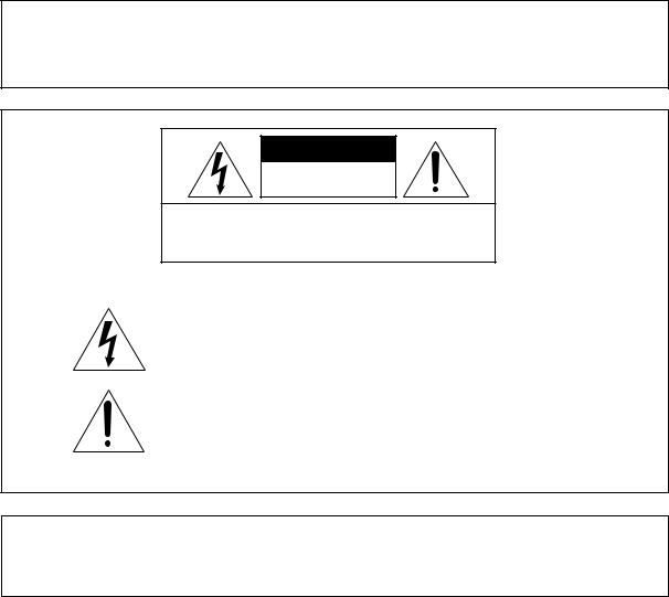
RISK OF ELECTRIC SHOCK
DO NOT OPEN
CAUTION: TO REDUCE THE RISK OF ELECTRIC SHOCK
DO NOT REMOVE COVER (OR BACK).
NO USER-SERVICEABLE PARTS INSIDE.
REFER SERVICING TO QUALIFIED SERVICE PERSONNEL.
THE SYMBOLS ARE RULED BY UL STANDARDS (U.S.A.)
The lightning flash with arrowhead symbol, within an equilateral triangle, is intended to alert the user to the presence of uninsulated “dangerous voltage” within the product’s enclosure; that may be of sufficient magnitude to constitute a risk of electric shock to persons.
The exclamation point within an equilateral triangle is intended to alert the user to the presence of important operating and maintenance (servicing) instructions in the literature accompanying the appliance.
5B-En
LITHIUM BATTERY
This product uses a lithium battery for memory back-up. The lithium battery should only be replaced by qualified service personnel. Improper handling may cause risk of explosion.
24A-En
Rev.3 2000/03/03

WARNING
WARNING: WHEN USING ELECTRIC PRODUCTS, BASIC PRECAUTIONS SHOULD ALWAYS BE FOLLOWED, INCLUDING THE FOLLOWING:
WARNING
Power requirements for electrical equipment vary from area to area. Please ensure that your DD8plus meets the power requirements in your area. If in doubt, consult a qualified electrician or AKAI professional dealer.
120 VAC |
@ 60 Hz for USA and Canada |
220~240 VAC |
@ 50 Hz for Europe |
PROTECTING YOURSELF AND THE DD8plus
•Never touch the AC plug with wet hands.
•Always disconnect the DD8plus from the power supply by pulling on the plug, not the cord.
•Allow only an AKAI professional dealer or qualified professional engineer to repair or reassemble the DD8plus. Apart from voiding the warranty, unauthorized engineers might touch live internal parts and receive a serious electrical shock.
•Do not put, or allow anyone to put any object, especially metal objects, into the DD8plus.
•Use only a household AC power supply. Never use a DC power supply.
•If water or any other liquid is spilled into or onto the DD8plus, disconnect the power, and call your dealer.
•Make sure that the unit is well-ventilated, and away from direct sunlight.
•To avoid damage to internal circuitry, as well as the external finish, keep the DD8plus away from sources of direct heat (stoves, radiators, etc.).
•Avoid using aerosol insecticides, etc. near the DD8plus. They may damage the surface, and may ignite.
•Do not use denaturated alcohol, thinner or similar chemicals to clean the DD8plus. They will damage the finish.
•Modification of this equipment is dangerous, and can result in the functions of the DD8plus being impaired. Never attempt to modify the equipment in any way.
•Make sure that the DD8plus is always well-supported when in use (in a specially-designed equipment rack).
•When installing the DD8plus in a 19" rack system, always allow 1U of ventilated free space above it to allow for cooling. Make sure that the back of the rack is unobstructed to allow a clear airflow.
•In order to assure optimum performance of your DD8plus, select the setup location carefully, and make sure the equipment is used properly. Avoid setting up the DD8plus in the following locations:
1.In a humid or dusty environment
2.In a room with poor ventilation
3.In any situation where the unit is not horizontal
4.Inside a vehicle such as a car, where it will be subject to vibration
5.In an extremely hot or cold environment
DD8plus Version 2.20 - September, 1998 |
i |

WARNING
WARNING
THIS APPARATUS MUST BE EARTHED
IMPORTANT
This equipment is fitted with an approved non-rewireable UK mains plug.
To change the fuse in this type of plug proceed as follows:
1)Remove the fuse cover and old fuse.
2)Fit a new fuse which should be a BS1362 5 Amp A.S.T.A or BSI approved type.
3)Refit the fuse cover.
If the AC mains plug fitted to the lead supplied with this equipment is not suitable for your type of AC outlet sockets, it should be changed to an AC mains lead, complete with moulded plug, to the appropriate type. If this is not possible, the plug should be cut off and a correct one fitted to suit the AC outlet. This should be fused at 5 Amps.
If a plug without a fuse is used, the fuse at the distribution board should NOT BE GREATER than 5 Amp.
PLEASE NOTE: |
THE SEVERED PLUG MUST BE DESTROYED TO AVOID A POSSIBLE SHOCK |
|
HAZARD SHOULD IT BE INSERTED INTO A 13 AMP SOCKET ELSEWHERE. |
The wires in this mains lead are coloured in accordance with the following code:
GREEN and YELLOW |
— EARTH |
BLUE |
— NEUTRAL |
BROWN |
— LIVE |
As the colours of the wires in the mains lead of this apparatus may not correspond with the coloured markings identifying the terminals in your plug, please proceed as follows:
The wire which is coloured GREEN and YELLOW must be connected to the terminal which is marked with the letter E or with the safety earth symbol  or coloured GREEN or coloured GREEN and YELLOW.
The wire which is coloured BLUE must be connected to the terminal which is marked with the letter N or coloured BLACK.
The wire which is coloured BROWN must be connected to the terminal which is marked with the letter L or coloured RED.
THIS APPARATUS MUST BE EARTHED
Ensure that all the terminals are securely tightened and no loose strands of wire exist.
Before replacing the plug cover, make certain the cord grip is clamped over the outer sheath of the lead and not simply over the wires.
6D-En
ii |
DD8plus Version 2.20 - September, 1998 |

WARNING
FCC WARNING
This equipment has been tested and found to comply with the limits for a Class A digital device, pursuant to Part 15 of the FCC Rules.
These limits are designed to provide reasonable protection against harmful interference when the equipment is operated in a commercial environment. This equipment generates, uses, and can radiate radio frequency energy and, if not installed and used in accordance with the instruction manual, may cause harmful interference to radio communications. Operation of this equipment in a residential area is likely to cause harmful interference in which case the user will be required to correct the interference at his own expense.
21A-En
This digital apparatus does not exceed the Class A limits for radio noise emissions from digital apparatus set out in the Radio Interference Regulations of the Canadian Department of Communications.
27-En
AVIS POUR LES ACHETEURS CANADIENS DU DD8plus
Le présent appareil numérique n’ément pas de bruits radioélectriques dépassant les limites applicables aux appareils numériques de la Class A prescrites dans le Règlement sur le brouillage radioélectrique édicté par le ministère des Communications du Canada.
27-F
VENTILATION
Do not prevent the unit's ventilation, especially by placing the unit on the soft carpet, in a narrow space, or by placing objects on the unit's chassis—top, side, or rear panels. Always keep the unit's chassis at least 10 centimeters from any other objects.
31C-En
Changes or modifications not expressly approved by the manufacturer for compliance could void the user’s authority to operate the equipment.
32-En
COPYRIGHT NOTICE
The AKAI DD8plus is a computer-based device, and as such contains and uses software in ROMs. This software, and all related documentation, including this Operator’s Manual, contain proprietary information which is protected by copyright laws. All rights are reserved. No part of the software or its documentation may be copied, transferred or modified. You may not modify, adapt, translate, lease, distribute, resell for profit or create derivative works based on the software and its related documentation or any part there of without prior written consent from AKAI professional M.I. Corp., Yokohama, Japan.
DD8plus Version 2.20 - September, 1998 |
iii |

WARNING
WARRANTY
AKAI professional M.I. Corp. warrants its products, when purchased from an authorized “AKAI professional” dealer, to be free from defects in materials and workmanship for a period of 12 (twelve) months from the date of purchase. Warranty service is effective and available to the original purchase only, and only on completion and return of the AKAI professional Warranty Registration Card within 14 days of purchase.
Warranty coverage is valid for factory-authorized updates to AKAI professional instruments and their software, when their installation is performed by an authorized AKAI professional Service Center, and a properly completed Warranty Registration has been returned to your “AKAI professional” dealer.
To obtain service under this warranty, the product must, on discovery of the detect, be properly packed and shipped to the nearest AKAI professional Service Center. The party requesting warranty service must provide proof of original ownership and date of purchase of the product.
If the warranty is valid, AKAI professional will, without charge for parts or labor, either repair or replace the defective part(s). Without a valid warranty, the entire cost of the repair (parts and labor) is the responsibility of the product's owner.
AKAI professional warrants that it will make all necessary adjustments, repairs and replacements at no cost to the original owner within 12 (twelve) months of the purchase date if:
1)The product fails to perform its specified functions due to failure of one or more of its components.
2)The product fails to perform its specified functions due to defects in workmanship.
3)The product has been maintained and operated by the owner in strict accordance with the written instructions for proper maintenance and use as specified in this Operator's Manual.
Before purchase and use, owners should determine the suitability of the product for their intended use, and owner assumes all risk and liability whatsoever in connection therewith. AKAI professional shall not be liable for any injury, loss or damage, direct or consequential, arising out of use, or inability to use the product.
The warranty provides only those benefits specified, and does not cover defects or repairs needed as a result of acts beyond the control of AKAI professional, including but not limited to:
1)Damage caused by abuse, accident, negligence. AKAI professional will not cover under warranty any original factory disk damaged or destroyed as a result of the owner's mishandling.
2)Damage caused by any tampering, alteration or modification of the product: operating software, mechanical or electronic components.
3)Damage caused by failure to maintain and operate the product in strict accordance with the written instructions for proper maintenance and use as specified in this Operator's Manual.
4)Damage caused by repairs or attempted repairs by unauthorized persons.
5)Damage caused by fire, smoke, falling objects, water or other liquids, or natural events such as rain, floods, earthquakes, lightning, tornadoes, storms, etc.
6)Damage caused by operation on improper voltages.
IMPORTANT NOTE: This warranty becomes void if the product or its software is electronically modified, altered or tampered with in any way.
AKAI professional shall not be liable for costs involved in packing or preparing the product for shipping, with regard to time, labor, or materials, shipping or freight costs, or time or expense involved in transporting the product to and from AKAI professional Authorized Service Center or Authorized Dealer.
AKAI professional will not cover under warranty an apparent malfunction that is determined to be user error, or owner's inability to use the product.
THE DURATION OF ANY OTHER WARRANTIES, WHETHER IMPLIED OR EXPRESS, INCLUDING BUT NOT LIMITED TO THE IMPLIED CONDITION OF MERCHANTABILITY, IS LIMITED TO THE DURATION OF THE EXPRESS WARRANTY HEREIN.
AKAI professional hereby excludes incidental or consequential damages, including but not limited to:
1)Loss of time.
2)Inconvenience
3)Delay in performance of the Warranty.
4)The loss of use of the product.
5)Commercial loss.
6)Breach of any express or implied warranty, including the Implied Warranty of Merchantability, applicable to this product.
iv |
DD8plus Version 2.20 - September, 1998 |

CONTENTS
INTRODUCTION ...................................................................................................................... |
1 |
SPECIFICATIONS ....................................................................................................... |
1 |
ABOUT THIS MANUAL ............................................................................................... |
5 |
TERMINOLOGY .......................................................................................................... |
5 |
FRONT PANEL ............................................................................................................ |
6 |
PLAY KEY ...................................................................................................... |
7 |
STOP KEY ..................................................................................................... |
7 |
REVERSE PLAY ............................................................................................ |
7 |
FAST FORWARD ........................................................................................... |
7 |
REWIND ......................................................................................................... |
7 |
REC ................................................................................................................ |
7 |
IN>OUT .......................................................................................................... |
7 |
TO .................................................................................................................. |
7 |
FROM ............................................................................................................. |
8 |
FRONT PANEL - INSERTING AN MO DISK ............................................................... |
9 |
DISK ACTIVITY LED ...................................................................................... |
9 |
DISK EJECT BUTTON ................................................................................... |
9 |
WRITE PROTECT SWITCH .......................................................................... |
9 |
REAR PANEL ............................................................................................................ |
10 |
OPTION SLOTS ........................................................................................... |
10 |
AKAINET CONNECTOR .............................................................................. |
10 |
TERMINATOR SWITCHES .......................................................................... |
10 |
SYNC CONNECTOR ................................................................................... |
10 |
EXPANSION CONNECTOR ........................................................................ |
10 |
SCSI-B ID SWITCHES ................................................................................. |
10 |
SCSI-A CONNECTOR ................................................................................. |
10 |
GROUND TERMINAL .................................................................................. |
10 |
MAINS INPUT .............................................................................................. |
10 |
PRE-READ LEVEL ....................................................................................... |
10 |
PRE-READ CONNECTOR ........................................................................... |
11 |
POWERING UP THE DD8 ........................................................................................ |
12 |
PLAY MODE ........................................................................................................................... |
13 |
MACHINE SLIP ......................................................................................................... |
13 |
SETTING TIMECODE OFFSETS ............................................................................. |
15 |
RECORD MODE .................................................................................................................... |
16 |
RECORD RUSHES ................................................................................................... |
19 |
NUDGE ................................................................................................................................... |
20 |
TRACK SLIP .......................................................................................................................... |
21 |
LOCATOR .............................................................................................................................. |
22 |
STORE ...................................................................................................................... |
22 |
GOTO ........................................................................................................................ |
22 |
LOCATING TO TIMECODE POSITIONS .................................................................. |
23 |
LOCATING TO LOCATOR MEMORIES .................................................................... |
23 |
LOCATING TO THE START OR END OF A PROJECT ............................................ |
23 |
DD8plus Version 2.20 - September 1998 |
v |

CONTENTS
DISK PAGES .......................................................................................................................... |
24 |
WRITE PROTECT PAGE .......................................................................................... |
24 |
NEW PROJECT PAGE .............................................................................................. |
24 |
LOAD PROJECT PAGE ............................................................................................ |
25 |
DIRECTORY PAGE ................................................................................................... |
27 |
UTILITIES PAGE ....................................................................................................... |
27 |
DISK INFO ................................................................................................................. |
27 |
FORMATTING DISKS ............................................................................................... |
28 |
NORMAL AND EXTENDED FORMAT DISKS ........................................................... |
30 |
UPDATING EXTENDED FORMAT DISKS ................................................................ |
30 |
CLEANUP DISK ........................................................................................................ |
31 |
CLEANUP .................................................................................................... |
31 |
MINIMISE ..................................................................................................... |
32 |
BACKING UP TO SCSI TAPE DRIVES ..................................................................... |
34 |
FORMATTING A TAPE FOR BACKUP ........................................................ |
34 |
BACKING UP SELECTED FILES ................................................................ |
36 |
BACKING UP ALL PROJECTS AND/OR LIBRARIES ................................. |
37 |
BACKING UP AN ENTIRE DISK .................................................................. |
37 |
PERFORMING THE BACKUP ..................................................................... |
37 |
VERIFYING A BACKUP ............................................................................... |
39 |
RESTORING A BACKUP ............................................................................. |
40 |
PERFORMING A RESTORE ........................................................................ |
41 |
RESTORING THE ENTIRE BACKUP .......................................................... |
45 |
NOTES ABOUT BACKUP/RESTORE .......................................................... |
46 |
SUGGESTIONS FOR BACKUP/RESTORE ................................................ |
47 |
TAKING CARE OF YOUR TAPE DRIVE ...................................................... |
48 |
COPYING DISKS ...................................................................................................... |
49 |
MACINTOSH DISK COMPATIBILITY ........................................................................ |
51 |
PROTOOLS IMPORT ................................................................................................ |
52 |
OMF IMPORT ............................................................................................................ |
53 |
NOTES CONCERNING OMF IMPORT ....................................................... |
53 |
AVID MEDIA-COMPOSER AND AUDIOVISION .......................................... |
53 |
UTILITIES PAGE ....................................................................................................... |
54 |
WAVEFRAME DISK COMPATIBILITY ....................................................................... |
55 |
FAIRLIGHT DISK COMPATIBILITY ........................................................................... |
56 |
EXPORT PROJECT PAGE ....................................................................................... |
57 |
DD1000 DISK COMPATIBILITY ................................................................................ |
58 |
LOADING DD1000 QLISTS ......................................................................... |
58 |
SAVING PROJECTS TO DD1000 DISKS .................................................... |
59 |
PLAYING DD1000 DISKS CREATED ON A DD8 ON A DD1000 ................. |
59 |
MULTIPLE DISK DRIVE SYSTEMS ............................................................ |
60 |
SYSTEM SETTINGS .............................................................................................................. |
62 |
DIGITAL SETTINGS .................................................................................................. |
62 |
88.2KHZ AND 96KHZ SAMPLE RATES ................................................................... |
65 |
DIGITAL OUTPUT FORMAT ..................................................................................... |
65 |
SYNC ......................................................................................................................... |
66 |
TIMECODE OFFSETS .............................................................................................. |
69 |
BIPHASE GENERATOR............................................................................................ |
70 |
ADVANCED TIMECODE OPTIONS .......................................................................... |
71 |
vi |
DD8plus Version 2.20 - September 1998 |

CONTENTS |
|
DISPLAY .................................................................................................................... |
72 |
DISPLAY OFFSET ..................................................................................................... |
73 |
FOOTAGE DISPLAY ................................................................................................. |
73 |
RECORD SETUP ...................................................................................................... |
74 |
RECORD CROSSFADES ............................................................................ |
74 |
RECORD MONITOR .................................................................................... |
74 |
RECORD MODES ........................................................................................ |
75 |
PUNCH IN/OUT MODES ............................................................................. |
78 |
ROUTING INPUTS .................................................................................................... |
79 |
SPEED ..................................................................................................................... |
79 |
SECOND SYSTEM SETTING PAGE ..................................................................................... |
80 |
OPERATING LEVEL ................................................................................................. |
80 |
PRE-READ ................................................................................................................ |
80 |
TIMES ........................................................................................................................ |
81 |
JOG ........................................................................................................................... |
81 |
REMOTE ................................................................................................................... |
82 |
THIRD SYSTEM SETTING PAGE .......................................................................................... |
85 |
TRACK MAPPING ..................................................................................................... |
85 |
SAVE SETTINGS ...................................................................................................... |
85 |
LOAD SETTINGS ...................................................................................................... |
85 |
CLEAR SETTINGS .................................................................................................... |
86 |
REAL-TIME CLOCK .................................................................................................. |
86 |
MULTI-MACHINE OPERATION ............................................................................................. |
87 |
DD8 AS AN RS422 MASTER .................................................................................... |
88 |
RS422 SETUP PAGE ................................................................................................ |
88 |
LAYBACK FUNCTION IN RS422 MASTER .............................................................. |
89 |
USING THE LAYBACK FUNCTION ............................................................. |
90 |
RS422 MASTER CONTROL OF NON-LINEAR VIDEO RECORDERS ...... |
90 |
RS422 SLAVE FUNCTIONS ..................................................................................... |
91 |
RS422 SLAVE - EAVESDROPPING MODE ................................................ |
91 |
RS422 SLAVE - FULL SLAVE MODE .......................................................... |
92 |
GPI/O ......................................................................................................................... |
92 |
APPENDIX 1 .......................................................................................................................... |
98 |
NOTES ON CHOOSING A DISK DRIVE ................................................................... |
98 |
NOTES REGARDING SCSI ...................................................................................... |
98 |
NOTES REGARDING THE USE OF MULTIPLE DISK DRIVES ............................... |
99 |
APPENDIX 2 ........................................................................................................................ |
100 |
OPTION BOARD INSTALLATION ........................................................................... |
100 |
INSTALLING IB-D8DA 8-CHANNEL ANALOG OUTPUT BOARD .......................... |
101 |
INSTALLING IB-D8AD 8-CHANNEL ANALOG INPUT BOARD .............................. |
101 |
INSTALLING DIGITAL INTERFACE BOARD .......................................................... |
102 |
INSTALLING GENERAL PURPOSE INTERFACE BOARDS .................................. |
102 |
INSTALLING BUFFER RAM EXPANSION .............................................................. |
103 |
INSTALLING EQ8 EQUALISER BOARD ................................................................ |
103 |
INSTALLING INTERNAL DISK DRIVE .................................................................... |
103 |
DD8plus Version 2.20 - September 1998 |
vii |

CONTENTS
APPENDIX 3 .......................................................................................................................... |
104 |
PIN WIRING - DD8 (and option boards) .................................................................. |
104 |
PRE-READ OUTPUT ................................................................................. |
104 |
ANALOG INPUT/OUTPUT CONNECTIONS ............................................. |
104 |
AES/EBU INPUT/OUTPUT CONNECTIONS ............................................. |
105 |
RS422 9-PIN CONNECTION ..................................................................... |
106 |
BI-PHASE INPUT ....................................................................................... |
106 |
BI-PHASE OUTPUT ................................................................................... |
106 |
PARALLEL (GPIO) CONNECTIONS.......................................................... |
107 |
PARALLEL (GPIO) INTERFACE ........................................................... |
108 |
GPIO OPTION BOARD BLOCK DIAGRAM ............................................... |
109 |
INDEX .................................................................................................................................. |
110 |
viii |
DD8plus Version 2.20 - September 1998 |
INTRODUCTION - 1
INTRODUCTION
The DD8plus is a magneto/optical-based, random-access digital film dubber designed to replace the current generation of magnetic film dubbers and multitrack tape machines used in most film and video post production environments. It features virtually instant locating, convenient removable media, flexible I/O and remote control options together with full data compatibility and seamless integration with the Akai DD1500 Recorder/Editor.
Being a dedicated system with no host computer required, its performance is optimised for ease of use and speed of operation with no prior knowledge of computers and/or hard disk digital recording required.
The DD8plus is a logical developmement from the original DD8 with new additional features including support for 20/24-bit audio recording at sample rates up to 96kHz.
SPECIFICATIONS |
|
General |
|
• Digital audio format: |
16-bit, 20-bit and 24-bit linear PCM |
• Simultaneous recording: |
8 tracks max. |
• Recording time: |
225 track-minutes |
|
(equivalent to 28 minutes/8 track with 2.6Gb MO disk) |
• Sampling rate: |
48k, 44.1k, 32kHz, 88.2kHz and 96kHz |
|
(with +0.1% Pull-up and -0.1% Pull-down at all sample rates) |
• Recording media: |
Optional 2.6Gb MO disk / Removable Hard Disk Unit |
• Internal drive: |
5.25-inch half-height drive bay x 1 mountable |
• Display: |
248 x 60 dot LCD x 1 - Time, Parameters |
|
8-segment LED x 8 - Peak Level Meter, Track Active, Track |
|
Slip |
|
Warning LED x 3 - Disk Busy, T/C RCV, W/C RCV |
• Memory : |
Flash ROM for OS and Settings |
|
72-pin SIMM x 1 for buffer memory expansion (EDO SIMM, |
|
any size from 2Mb to 32Mb) |
• Expansion slot: |
General purpose slot x 4 |
|
Digital audio slot x 1 - TDIF, ADAT or AES/EBU |
|
8-channel analog audio input slot x 1 |
|
8-channel analog audio output slot x 1 |
|
EQ8 slot (internal) x 1 |
• Dimensions: |
482.6 (W) x 177 (179) (H) x 410 (441.2) (D)mm (max.), 4U |
• Weight: |
12.8 kg (no options) |
• Power: |
100-120 / 220-240 VAC, 50 / 60Hz, 90W |
DD8plus Version 2.20 - September 1998 |
Page 1 |

INTRODUCTION - 1
Connections |
|
• Video Sync / Word Clock input: |
BNC x 1 with 75-ohms terminator switch |
• AKAINET (Ethernet): |
BNC connector x 1 with 50-ohms terminator switch |
• Pre-Read output: |
9-pin D-sub x 1, 14.5Vrms (max.), 560Ω |
• Expansion port: |
9-pin D-sub x 1, for RC15 |
• SCSI-A: |
50-pin Amphenol x 1 for disk expansion |
• Phones: |
1/4-inch stereo phone x 1, 15mW 32Ω |
• DIP switch x 1 for SCSI-B ID selection
Options
• IB-D8AD - 8-channel analog input board
Balanced inputs, input imp. 104kΩ; Max. input level +24dBu 25-pin D-sub (TASCAM DA-88 pin assignment)
A/D converter 24-bit, 128-times oversampling
Operating level selectable by software [-12, -16, -18 or -20dBu]
• IB-D8DA - 8-channel analog output board
Balanced outputs, output imp. 94Ω ; Max. output level +24dBu 25-pin D-sub (TASCAM DA-88 pin assignment)
D/A converter: 20-bit 8-times oversampling
Operating level selectable by software [-12, -16, -18 or -20dBu]
• IB-D8TIF - 8-channel TDIF digital input/output board
25-pin D-sub (TASCAM DA-88 pin assignment) with BNC connector for Word Clock Out and 15-pin D-sub (TASCAM DA-88 pin assignment) for TASCAM MU-8824 Meter Bridge connection
• IB-D8MA24 - 8-channel AES/EBU 24-bit digital input/output board 25-pin D-sub connector x 1
• IB-802T - LTC interface board
1/4” phone connector x 2
• IB-803M - MIDI interface board 5-pin DIN connector x 3
• IB-804A - 8-channel ADAT optical digital input/output board Optical connector x 2
• IB-805R - RS422 interface board
9-pin D-sub connector x 1
• IB-806B - Biphase interface board 9-pin D-sub connector x 2
• IB-808G - GPIO parallel interface board 37-pin D-sub connector x 1
• EQ8 - 8-channel EQ board
For the interchangeability of DR8/DR16/DD1500 disks
Page 2 |
DD8plus Version 2.20 - September 1998 |

INTRODUCTION - 1
•DL1500 - Remote Controller
•RC15 - User Assignable Remote Controller
*Restriction of board installation: TDIF, ADAT or Multi-AES/EBU interface
Standard accessory
•Cable set for AD/DA boards and SCSI Drive connection: 1
•Power cable: 1
•Operator’s manual: 1
(0dBu = 0.775Vrms)
Trademarks:
Open Media Framework and OMF are trademarks of Avid Technology, Inc. Macintosh is a registered trademark of Apple Computer, Inc. All other product and company names are the property of their respective owners.
DD8plus Version 2.20 - September 1998 |
Page 3 |

INTRODUCTION - 1
FEATURES
•8-track operation with immediate removability on Magneto Optical (MO) disk (no backup required) or removable hard disks. Record times for one side of a 2.6Gbyte MO disk are 3 hours 40 minutes of mono 16-bit recording at 48kHz and 4 hours of mono 16-bit at 44.1kHz. Effective playback time can be extended using extra MO drives and up to seven drives in total may be connected using SCSI.
•Plug-and-Play replacement for the Tascam DA-88
•Options include SMPTE/EBU IN and OUT (at all frame rates), Bi-phase IN and OUT, and RS422 (Sony™ P2 9-pin protocol) .
•The DD8 will convert SMPTE/EBU to Bi-phase and vice versa.
•The DD8 can follow external timecode backwards and forwards, even at slow speeds.
•Wordclock and video sync inputs fitted as standard allowing synchronisation to house sync, digital audio and PAL/SECAM and NTSC video sync sources.
•20-bit digital to analogue converters (DACs) with 8 x oversampling and software adjustable operating level.
•24-bit analogue to digital converters (ADCs) with 128 x oversampling and software adjustable operating level.
•Custom LSI dedicated for signal processing ensures fast and reliable operation.
•32 channel ‘polyphony’ allows long crossfades or overlaps to be achieved within a single track and across all 8 tracks simultaneously.
•Dedicated MTR-style transport keys for play, stop, rewind, fast forward and record.
•The JOG wheel allows you to ‘scrub’ audio across all 8-tracks for editing.
•AKAINET link (a subset of the Ethernet protocol) fitted as standard to allow true remote control of multiple DD8s from a single DL1500 controller with virtually no limit on distance.
•16, 20 and 24-bit audio recording capabilities
•Direct playback of files created on a variety of other manufacturers digital audio workstations.
Page 4 |
DD8plus Version 2.20 - September 1998 |

INTRODUCTION - 1
ABOUT THIS MANUAL
This owner’s manual has been written to provide you with the information to get the best from the DD8plus. Although it hoped that the DD8plus is easy enough to use without constant reference to this manual, please take the time to read it in order to understand the machine fully. The manual takes you through the machine from scratch, assuming you have just installed it and you are using it for the first time.
This manual covers all basic functions and operation and, wherever possible, gives hints and tips and application notes. However, because of the diversity of applications in which the DD8plus can be used, it is not always possible to cover every application specifically. As such, most descriptions of functions are fairly general unless, however, a certain function has a specific use in a particular application.
It is assumed that the DD8plus is being used in audio to picture, the main application for which it was designed, and it is assumed you have some experience of the techniques involved in this field.
This operating manual was originally written for the DD8 but also includes details of features specific to the DD8plus. Where then name DD8 is used, this can be assumed to refer to the DD8plus as well.
As with any piece of new gear, there is always a bit of new jargon to get to grips with. What follows, therefore, is a short list of some of the terms you will come across during the course of this manual.
PROJECT |
This is where you do the bulk of your work on the DD8 and con- |
|
tains all your recordings, positioned at the required times. Think of |
|
it as a reel of multi-track tape if you like, although a project on the |
|
DD8 is actually nothing more than a Qlist or EDL linking cues to |
|
timecode. |
|
The SYSTEM settings, locator memories etc. are also saved with |
|
the project and when a project is subsequently loaded, the whole |
|
system is restored to exactly the status the project was saved in. |
NOW TIME |
The NOW TIME is the DD8’s current internal time position. All work |
|
is done with referenced to this NOW time. The NOW time is dis- |
|
played on many of the LCD pages. |
CUE |
This refers to a piece of audio from its start to its end. |
EDIT REGION |
This refers to the area selected between the IN and the OUT points. |
IN TIME |
This usually refers to the start of an edit (e.g. NUDGE). However, |
|
the IN TIME is also used to set cycle times. |
OUT TIME |
This usually refers to the end of an edit (e.g. NUDGE) although it is |
|
also used to set cycle times. |
MARK POINT |
This is a special marker intended for Biphase synchronisation. It |
|
can be set to define a sync point between audio and film (usually a |
|
cross before the first frame). |
LIBRARY |
A library is a file created for convenient storage of groups of cues |
|
(referred to as ‘clips’). For example, a library may contain sound |
|
effects, or music cues, etc.. Although this is not available from the |
|
front panel due to the restriced user interface, the DD8plus in- |
|
cludes full support for handling library files when a DL1500 remote |
|
controller is attached. |
DD8plus Version 2.20 - September 1998 |
Page 5 |

INTRODUCTION - 1
FRONT PANEL
JOG / SPOOL
DIGITAL DUBBER
POWER |
|
|
|
ON |
CLIP |
CLIP |
W/C |
|
|
|
RCV |
|
REF |
REF |
|
|
ACTIVE |
|
T/C |
|
|
|
RCV |
TRK SLIP
1 |
2 |
3 |
4 |
5 |
6 |
7 |
8 |
OFF |
|
|
|
|
|
|
|
|
|
ALL / 0 |
1 |
2 |
3 |
4 |
5 |
6 |
7 |
8 |
9 / SYNC |
PANEL |
|
|
|
|
|
|
|
|
|
ENABLED |
PLAY |
|
RECORD |
|
NUDGE |
|
TRACK SLIP |
|
|
|
|
|
|
|
|
F 1 |
F 2 |
F 3 |
F 4 |
F 5 |
F 6 |
CYCLE |
IN-> |
TO |
FROM |
|
OUT |
||||
|
|
|
START END
REC
JOG / SPOOL
DATA – |
DATA + |
DISABLED
LEVEL
DISK BUSY
MIN |
MAX |
|
|
|
|
|
|
|
PHONES |
DISK |
GO TO |
STORE |
ENTER |
ESCAPE |
UNDO |
SYSTEM |
|
Next to the Power Switch, the 8 LED barmeter displays are used as peak level meters as well as indicating the track’s status:
ACTIVE |
Audio data being played from disk. |
TRK SLIP |
Audio track slipped in time from its original location. |
The W/C RCV LED is used to indicate the status of the external word clock input. When external sync is selected, this indicator will light steadily when the correct word clock signal is being received. If there is a problem with the word clock signal, this LED will flash.
Similarly, the T/C RCV LED is used to indicate the status of the external timecode input. When external timecode is being received successfully, the DD8 will play synchronised to that timecode and the T/C RCV LED will be steadily lit. If at any time, the T/C RCV LED flickers, this indicates a problem with the external timecode such as dropout. The DD8 will ‘flywheel’ for a short while in the event of timecode dropout but, if the dropout is too long, the DD8 will stop playing.
Under the power switch, the PANEL ENABLE/DISABLED switch is used to lock the keys on the front panel to prevent accidental operation.
The PLAY, RECORD, NUDGE and TRACK SLIP keys are used to select one of the DD8’s ‘PROJECT’ modes, and also determine the current function of the track select keys (1~8 and ALL).
In the ‘PROJECT’ modes, the track select keys (1~8, ALL) are used for selecting tracks. They can also be used in some of the setup pages as a numeric keypad. In this situation, the ALL key is used as ‘0’ and the SYNC key is used as ‘9’.
Under the LCD display are 6 soft keys (F1 ~ F6) used to select items on the LCD.
The type of action performed when one of the soft keys is pressed is indicated by the style of the soft key display shown on the bottom line of the LCD:
• Accessing another page
• Executing a function
• Moving the cursor to the indicated field
Page 6 |
DD8plus Version 2.20 - September 1998 |
INTRODUCTION - 1
Under the soft keys are the transport keys which are designed to emulate those on an MTR as closely as possible. The keys are:
CYCLE |
When the CYCLE key is pressed, the DD8 will start playback from |
|||||||||||||||
|
|
|
the current time and then continue to repeat between the IN and |
|||||||||||||
|
|
|
OUT times previously stored. |
|||||||||||||
|
|
|
This is the PLAY key. |
|||||||||||||
|
|
|
||||||||||||||
|
|
|
This is the STOP key and will stop playback, recording, rewind and |
|||||||||||||
|
|
|
||||||||||||||
|
|
|
fast forward. |
|||||||||||||
|
|
|
This is the REVERSE PLAY key. Pressing it will cause the DD8 to |
|||||||||||||
|
|
|
play backwards. This is a technique used a lot in film applications |
|||||||||||||
|
|
|
where mixing engineers actually mix down backwards in order to |
|||||||||||||
|
|
|
save time. However, please note that you cannot record backwards. |
|||||||||||||
|
|
|
This is fast forward. Pressing it once gives x 10 play speed; press- |
|||||||||||||
|
|
|
||||||||||||||
|
|
|
ing it again gives x 100 play speed. |
|||||||||||||
|
|
|
When |
|
|
|
|
|
is pressed during play, the DD8 will fast forward with |
|||||||
|
|
|
|
|
||||||||||||
|
|
|
|
|
|
|
|
|
|
|
|
|
|
|
||
|
|
|
‘tape chatter’ just like a standard MTR. In this case, only x 5 play |
|||||||||||||
|
|
|
speed is possible. |
|||||||||||||
|
|
|
This is rewind. Pressing it once gives x 10 play speed; pressing it |
|||||||||||||
|
|
|
again gives x 100 play speed. |
|||||||||||||
|
|
|
When |
|
|
|
|
|
|
is pressed during play, the DD8 will rewind with ‘tape |
||||||
|
|
|
|
|
|
|
|
|
||||||||
|
|
|
chatter’ just like a standard MTR. In this case, only x 5 play speed |
|||||||||||||
|
|
|
is possible. |
|||||||||||||
REC |
This key allows you to drop in and out of record just like a normal |
|||||||||||||||
|
|
|
MTR. Press |
|
plus REC together to drop in and press |
|
(or |
|
) to |
|||||||
|
|
|
|
|
|
|||||||||||
|
|
|
drop out of record. |
|||||||||||||
IN > OUT |
This will play from the IN point to the OUT point. I.e.: |
|||||||||||||||
|
|
|
Because the DD8 automatically places the IN and OUT times at |
|||||||||||||
|
|
|
the start and end of a new recording, you may use PLAY IN>OUT |
|||||||||||||
|
|
|
to check it immediately after recording. |
|||||||||||||
TO |
This will play up to the NOW time. I.e.: |
|||||||||||||||
NOW
PLAY TO 
|
This is useful for checking things prior to editing (i.e. to find a good |
||||
|
edit point) but may also be used for checking things on the NOW |
||||
|
time generally. |
||||
FROM |
This plays from the NOW time for a specified duration. I.e.: |
||||
|
|
NOW |
|||
|
|
|
|
|
|
|
PLAY FROM |
|
|
|
|
|
|
|
|
||
|
|
|
|
|
|
|
|
|
|
|
|
|
|
|
|
|
|
DD8plus Version 2.20 - September 1998 |
Page 7 |

INTRODUCTION - 1
Next to the LCD is the JOG/SPOOL wheel. The function of this wheel is selected by the JOG/ SPOOL key. Pressing this once will select the JOG function and the LED will light steadily. Pressing it again will select the SPOOL function and the LED will flash.
The DATA-/DATA+ keys are used to set or change parameter values.
Next to the disk drive bay is the DISK key. Pressing this enters the DISK mode where you can select functions which are related to the disk drive(s) attached to the system.
The GOTO and STORE keys access the locator pages which allow you to quickly locate the transport to the required position.
The ENTER key is used to confirm actions or to complete the entry of names, numbers or timecode values. The ESCAPE key is used abort or cancel the process without committing it. This is your ‘escape route’ should you be in a situation where you change your mind. The ESCAPE key can also be used to take you out of the current page and back to the main play/record mode.
The UNDO key allows you to undo/redo the last thing you did. If you make a mistake and do something you’re not happy with, press UNDO and the original data will be restored. If you then find that you preferred the mistake, press UNDO again to restore the previous version.
NOTE 1: The UNDO function only refers to recording and editing. You cannot undo anything else. For example, if you load a project and change your mind, you cannot undo that. If you select some tracks for edit when you really meant to select them for record, you cannot undo that.
NOTE 2: IT IS NOT POSSIBLE TO USE UNDO IF YOU DELETE A FILE (I.E. A PROJECT) BY MISTAKE. PLEASE TAKE CARE WHEN DELETING FILES.
The SYSTEM key is used to select pages where you can set many parameters to select the current operational state of the DD8.
Finally, on the other side of disk drive bay, the PHONES connector outputs a mix of all tracks selected for playback. The headphone level is adjusted by the LEVEL control above the connector.
Page 8 |
DD8plus Version 2.20 - September 1998 |
INTRODUCTION - 1
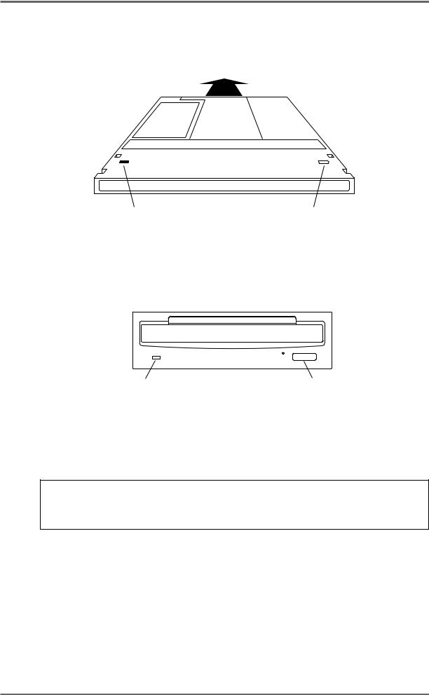
FRONT PANEL - INSERTING AN MO DISK
Assuming you have an MO drive installed, the disk is inserted thus:
WRITE PROTECT SWITCH |
WRITE PROTECT SWITCH |
(This side) |
(Other side) |
The side you wish to use is inserted face up. Power must be on for the disk to be accepted as the load mechanism is motorised.
Disk Activity Led |
Eject switch |
When the disk is in use (i.e. playing back, recording, saving, loading, etc.), the DISK ACTIVITY LED will flash.
To eject the disk, press the DISK EJECT button. Power must be on for the disk to be ejected as the mechanism is motorised.
NOTE: If there is some problem ejecting the disk and/or power is not applied to the drive, you can eject the disk by inserting a small metal tool in the small hole alongside the disk eject button. Something like a rolled out paper clip will do it but a special tool is recommended. This tool may accompany the drive unit.
It is possible to write protect MO disks to prevent accidental erasure, editing, formatting, etc.. To do this, slide the WRITE PROTECT switch to the PROTECT position. If you only intend to playback from the disk, it is a wise precaution to write protect the disk to prevent accidental damage to a project.
DD8plus Version 2.20 - September 1998 |
Page 9 |
INTRODUCTION - 1
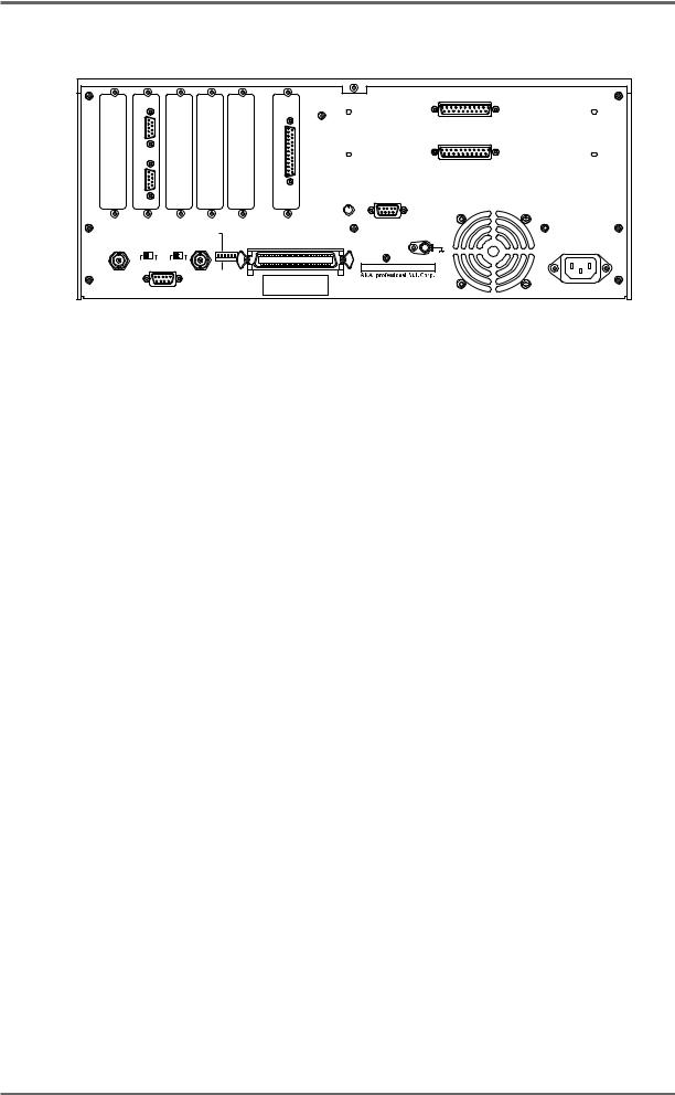
REAR PANEL
|
BIPHASE |
|
|
|
|
|
|
ANALOG INPUT |
|
|
|
|
|
|
|
|
|
||
|
SYNC |
|
|
|
|
AES/EBU |
|
|
|
|
|
|
|
|
|
|
|
|
|
|
|
|
|
|
|
|
DIGITAL I/O |
|
|
|
IN |
|
|
|
|
|
|
|
|
|
|
|
|
|
|
|
|
|
ANALOG OUTPUT |
|
OUT |
|
|
|
|
|
|
|
|
|
|
|
|
|
|
|
LEVEL |
PRE-READ |
|
|
|
|
|
|
|
|
MIN |
MAX |
|
|
|
|
|
|
MASTER |
|
|
GND |
|
|
|
|
|
|
|
|
SCSI-B ID |
|
|
AKAI NET. |
TERM |
TERM |
SYNC |
|
|
|
|||
IN /OUT |
|
SCSI-A |
|
|
|||||
|
|
|
|
|
OFF NC |
T 4 2 1 |
|
|
|
|
|
|
|
|
|
|
|
||
|
ON |
OFF |
ON |
OFF |
|
ON |
|
|
MODEL NUMBER DD8plus |
|
|
|
|
|
|
|
|
|
|
|
|
|
|
|
|
SLAVE |
|
|
|
|
|
|
|
|
|
|
|
|
1-3, HIRANUMA 1-CHOME, NISHI-KU, |
|
|
|
|
|
|
|
|
|
YOKOHAMA , JAPAN |
|
|
EXPANSION |
|
|
|
|
|
MADE IN JAPAN |
|
OPTION SLOTS
There are six slots on the rear panel for installing option cards. The first four slots from the left hand side are for general purpose interface cards such as the IB-805R (RS422 interface) or the IB-806B (Biphase interface). The fifth slot is for a digital audio interface card such as the IB-D8TIF (TDIF interface), IB-D8MA24 (AES/EBU interface) or IB-804A (ADAT interface). The final slot is for the connector to the Tascam MU-8824 Meter Bridge (this is part of the IB-D8TIF option card).
There are two more slots available for installing the analog option cards IB-D8AD (8-channel analog input) and IB-D8DA (8-channel analog output).
AKAINET CONNECTOR
This connector is used to connect the DD8 to the DL1500 Remote Controller
TERMINATOR SWITCHES
These switch selects 75Ω termination for the SYNC connector for use with video sync signals and 50Ω termination for the AKAINET connector.
SYNC CONNECTOR
This BNC can accept either TTL wordclock or video sync signals (such as ‘black and burst’ house sync signals) and is used to synchronise the DD8 to an external clock source.
EXPANSION CONNECTOR
This connector is used to attach the optional RC15 User Assignable Remote Controller.
SCSI-B ID SWITCHES
These DIP switches are not in use at the moment (Note that this switch has no effect on the SCSI-A bus).
SCSI-A CONNECTOR
This 50-pin Amphenol connector is used to connect external SCSI drives to the DD8.
GROUND TERMINAL
This terminal is provided to allow you to earth the DD8 in the event of ground loops.
MAINS INPUT
Mains power is connected here.
PRE-READ LEVEL
This control is used to adjust the level of the oscillator signal that will be generated at the preread output connector.
Page 10 |
DD8plus Version 2.20 - September 1998 |
INTRODUCTION - 1
PRE-READ CONNECTOR
This connector can be used to replace the ‘pre-read’ output generated by some dubbers that have a second playback head mounted before the main playback head. Note that the DD8 does not generate an audio signal here. Instead, it uses an oscillator which is switched on and off as the playback signal reaches a preset threshold.
DD8plus Version 2.20 - September 1998 |
Page 11 |
INTRODUCTION - 1
POWERING UP THE DD8
It is recommended that the following power up procedure is observed when turning the system on:
First, turn on any disk drives that may be connected to the system. Next, turn on the DD8. You will see this screen display momentarily:
The DD8 will look at the disk drives attached to the system. If a disk containing a valid PROJECT is found, it will be loaded automatically and you will see the main playback screen:
If no projects are found, the DD8 will enter the NEW PROJECT page in DISK mode, which will be explained later in Disk mode, to allow you to setup the disks attached to the system and create a new PROJECT:
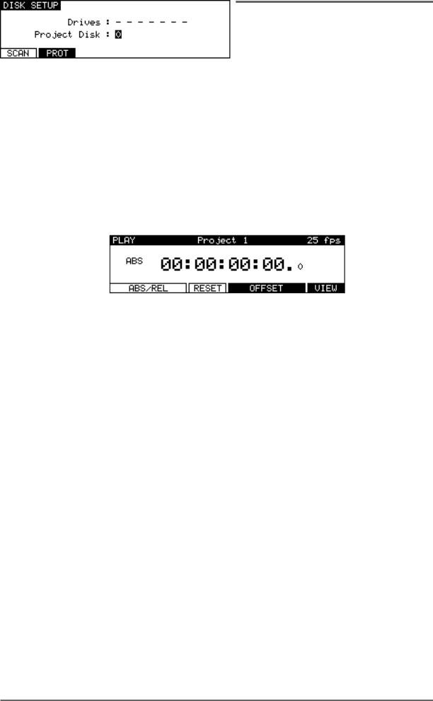
If no disk is found, it goes directly to the DISK SETUP page in DISK mode:
In this case, check the connections to the disk drive (and SCSI termination) and then press the SCAN key to search the SCSI bus again.
Page 12 |
DD8plus Version 2.20 - September 1998 |
PLAY MODE - 2
PLAY MODE
The PLAY mode is the default mode when a Project is loaded. It can also be accessed at any time by pressing the PLAY key under the barmeters. Pressing the track keys 1-8 located under the barmeters select the playback tracks to be muted. The tracks with lit LEDs indicate muted tracks. Pressing the track key again disables the mute.
The Soft Keys’ functions depend on the External Time Source selected in the SYSTEM/SYNC menu. When a Biphase time source is selected, the PLAY screen will look similar to this:
The top line of the screen shows the name of the current Project, as well as the current frame rate of the timecode display.
The time display style and sub-frame display depend on the parameters set in the SYSTEM/ DISPLAY menu. In the example shown above, the timecode display style has been set to display footage. However, it is also possible to select ‘conventional’ timecode formats in which case the display will look something like this:
The top line of the screen shows the name of the current Project, as well as the current frame rate.
Pressing the RESYNC RCV key (F1/F2) resets the biphase reader to the current position.
The RESET key (F3) resets the time counter to zero at the current position.
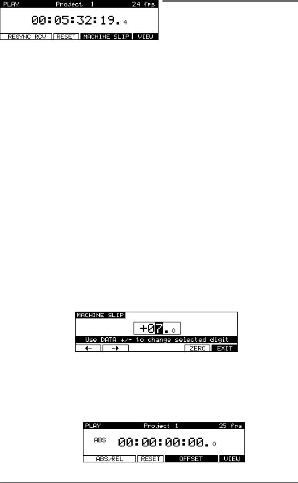
Pressing MACHINE SLIP (F4/F5) takes you to the MACHINE SLIP page :
This page allows you to slip the DD8’s time with respect to the biphase machine. F1 and F2 are used to move the cursor to the correct position (frames or sub-frames), and the DATA +/- keys are used to adjust the value. Note that the Sub-Frame value (1/10th frame, 1/4th frame, 1/2 frame) depends on the setting in SYSTEM/DISPLAY (10th Frame, Film Perfo, Video Field). The ZERO key (F5) resets the offset to zero.
When an external time source other than biphase is selected, the PLAY screen will look like this:
DD8plus Version 2.20 - September 1998 |
Page 13 |
PLAY MODE - 2
When an External Time Source is selected and the SYNC key is switched on, an additional display on the main PLAY screen indicates when the DD8 is chasing the external time:
When the DD8’s internal time is at the same position as the external time (and the sample rate is synchronised to the speed of the external time source), the CHASE display will change to LOCK.
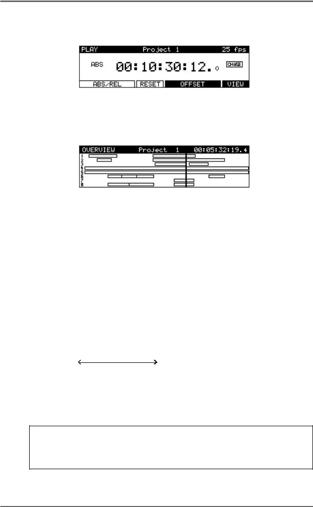
Pressing the VIEW key (F6) switches to the OverView display :
This page shows a static view of the entire Project, with the NOW time scrolling across the screen. The ESCAPE key (or any mode key) is used to exit this display.
Returning to the main PLAY screen, sometimes, you may prefer to set an offset between the DD8’s timecode display and the timecode position of an external machine. For example, your project may start at 00:00:00:00 but the visuals start at 10:00:00:00. Using the soft keys on this page, you may set offsets so that the two machines play in sync without having to extensively modify the project’s start time.
Pressing the ABS/REL (F1/F2) key sets the time display in absolute mode.
Pressing the ABS/REL (F1/F2) key again sets the time display in relative mode which allows the 00:00:00:00.0 reference time to be placed at a time other than absolute zero. For example:
ABS(solute) |
0 |
8 |
23.59 |
||||||||||||||||||||||
REL(ative) |
|
|
|
|
|
|
|
|
|
|
|
|
|
|
|
|
|
|
|
|
|
|
|
|
|
|
|
|
|
|
|
|
|
|
|
|
|
|
|
|
|
|
|
|
|
|
|
|
|
|
|
|
|
|
|
|
|
|
|
|
|
|
|
|
|
|
|
|
|
|
|
|
|
|
|
|
|
-8 |
0 |
15.59 |
|||||||||||||||||||||||
ZERO IS AT : + 08:00:00:00.0
Pressing the RESET (F3) key resets the relative time to zero at the current position.
Pressing the OFFSET key (F4/F5) takes you to the Offset page where you can manually enter the time offset between ABS time and REL time.
NOTE: You may find it useful when starting a project from scratch to always start at, say,
1 hour and use the relative time display so that the project effectively still starts at zero. In this way, if you suddenly find you need to add cues before 00:00:00:00, you can. If you use absolute and start at zero, you will first have to slip all cues in the project forward to accommodate the new cues.
Page 14 |
DD8plus Version 2.20 - September 1998 |

PLAY MODE - 2
SETTING TIMECODE OFFSETS
Pressing the ZERO (F1) key resets the offset to zero. When following timecode from an external machine, pressing the GRAB (F2) key grabs the offset between the current NOW time (internal) and the current External Time value.
If the project starts at 00:00:00:00.0 but the incoming timecode starts at 1 hour, you should set an OFFSET of -01:00:00:00.0. This will subtract 1 hour from the incoming timecode, thereby effectively providing the DD8 with timecode starting at 00:00:00:00.0. Conversely, if the project starts at, say, 10 hours but the incoming timecode starts at 1 hour, you would need to set an offset of +09:00:00:00.0 , adding 9 hours to the incoming timecode so that it plays from 10 hours.
In cases where the project and the incoming timecode both start at odd times (for example, when the project starts at 02:23:45:23.0 and the incoming timecode starts at, say, 09:12:12:14.0), your best bet is to use the GRAB softkey. Locate the project and the incoming timecode to their respective start times and press GRAB. The offset will be calculated automatically.
Pressing ENTRY (F5) enters the Offset Entry page which allows you to manually enter an offset value or nudge the current offset value:
Soft keys F1 and F2 can be used to move the cursor to the sub-frame field, or any of the other fields. The offset time is then entered using the track keys as a numeric keypad or the current digit can be nudged using the DATA +/- keys.
The offset sign (plus or minus) can be toggled by pressing the +/- key (F4).
DD8plus Version 2.20 - September 1998 |
Page 15 |
RECORD MODE - 3
RECORD MODE
The RECORD mode is the default mode when a New Project is created. It can also be selected by pressing the RECORD key below the barmeters. In this mode, the track select keys (1~8) are used for selecting tracks to record onto.
The Time Display Style and Sub-Frame display depend on the according parameters in the SYSTEM/DISPLAY menu. However, “Free on Disk” is always shown in real time (hh:mm:ss).
When not recording, the following display is shown:
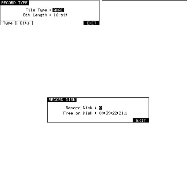
The top line of the screen shows the name of the current Project, as well as the current frame rate. Pressing DISK (F1) takes you to the Record Disk page :
Here you may select the SCSI ID of the disk onto which new audio will be recorded. This page also shows you how much available recording time there is on tracks enabled for record.
Pressing SETUP (F2) takes you directly to the RECORD SETUP screen which is described later in this manual in the System Section.
Pressing TYPE (F3) takes you to the RECORD TYPE page where you can select certain options for new recordings:
The TYPE key (F1) is used to move the cursor to the FILE TYPE field. The BITS key (F2) is used to move the cursor to the BIT LENGTH field.
FILE TYPE |
This selects the type of audio file that will be created when new recordings |
|
are made. The options available in this field depend on the format of the |
|
selected Record Disk. |
|
• AKAI: This is the DD’s native audio file format and is only available when |
|
the selected Record Disk is an AKAI format |
|
• AIFF:This is Apple’s “Audio Interchange File Format” that is used by many |
|
Macintosh software applications. The AIFF option is only available when the |
|
selected Record Disk is Macintosh format |
|
• SD-II: This is the native audio file format used by Digidesign Pro Tools and |
|
some other Macintosh software applications. The SD-II option is only avail- |
|
able when the selected Record Disk is Macintosh format |
|
• AKAI->FAIRLIGHT: This allows special Akai audio files to be created which |
|
are intended for playback on a Fairlight MFX3plus system fitted with Akai |
|
File Exchange support. This option is only available when the selected Record |
|
Disk is an AKAI format |
|
|
Page 16 |
DD8plus Version 2.20 - September 1998 |
RECORD MODE - 3
BIT LENGTH |
This selects the audio bit length for new recordings. |
|
|
|
|
|
|
|
|
|||||||
|
• 16-bit: This is the compact Disc standard. |
|
|
|
|
|
|
|
|
|||||||
|
• 20-bit: This option allows 20-bit audio to be recorded, giving greater resolu- |
|||||||||||||||
|
tion and headroom. |
|
|
|
|
|
|
|
|
|
|
|
|
|||
|
• 24-bit: This option allows 24-bit audio to be recorded, giving even greater |
|||||||||||||||
|
resolution and headroom. |
|
|
|
|
|
|
|
|
|
|
|
|
|||
|
• 20-bit (packed): This is a special option that is only available when record- |
|||||||||||||||
|
ing AKAI format audio files. Typically, 20-bit audio occupies the same space |
|||||||||||||||
|
on disk as 24-bit audio (the extra 4-bits of storage space in each sample |
|||||||||||||||
|
being wasted). The 20-bit ‘packed’ mode avoids this waste of space by writ- |
|||||||||||||||
|
ing the audio to disk in a special pattern. |
|
|
|
|
|
|
|
|
|
|
|||||
|
|
|
|
|
|
|
|
|
|
|
|
|
|
|
|
|
|
24-BIT : |
|
|
|
Sample 1 |
Sample 2 |
|
Sample 3 |
|
|
||||||
|
|
|
|
|
|
|
|
|
|
|
|
|
||||
|
20-BIT : |
|
|
|
Sample 1 |
|
Sample 2 |
|
Sample 3 |
|
|
|
||||
|
|
|
|
|
|
|
|
|
|
|
|
|
||||
|
20-BIT PACKED : |
|
|
|
Sample 1 |
|
Sample 2 |
|
Sample 3 |
|
|
|
|
|
|
|
Note that this mode does not involve any ‘audio compression’. It just places the data on disk in an optimal manner to maximum disk storage space and bandwith.
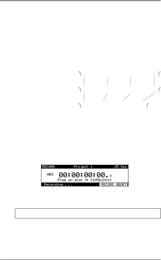
Once you have selected your recording tracks, to record, simply press PLAY (to start playback) and then press PLAY and the RECORD key together. The track key(s) will be steadily lit as will the transport RECORD key.
During recording, the screen changes as follows :
Pressing RECORD ABORT (F5/F6) aborts the recording process.To stop recording, press STOP. To drop out of record (i.e. stop recording but keep playing), simply press PLAY - the DD8 will drop out of record and keep playing.
NOTE: There is a minimum time before you can punch in to record again after punching out. This is due to disk speed and will depend on the drive you are using.
It is also possible to start recording from stop by pressing the REC key first and then pressing PLAY. You can stop recording by pressing PLAY again or by pressing STOP.
DD8plus Version 2.20 - September 1998 |
Page 17 |
RECORD MODE - 3
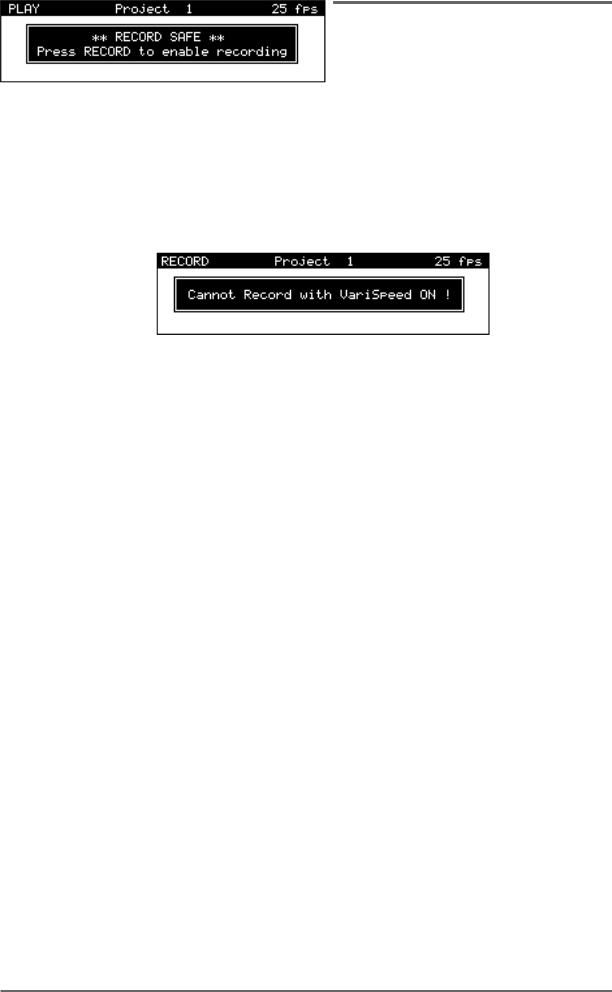
If the DD8 is in a mode other than RECORD (i.e PLAY, NUDGE or TRACK SLIP), the following message will appear when you try to start recording:
If VariSpeed is ON (and different from 0 %), the following prompt will appear when you try to start recording:
UNDOING A RECORDING
If you don’t like the recording you just made, the simplest way to repair it is probably to record over it just like tape. Another way out of a recording disaster is to undo the last recording you made by pressing the UNDO key (the key’s LED will light). Of course, should you change your mind, you can redo the recording by pressing the UNDO key again (the LED will switch off).
Page 18 |
DD8plus Version 2.20 - September 1998 |
RECORD MODE - 3
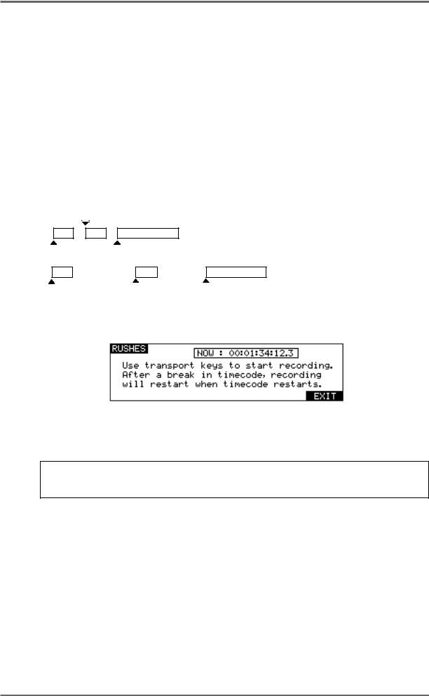
RECORD RUSHES
When recording ‘dailies’ at a film or video shoot, recordings are made referenced to ‘time of day’ timecode on a portable recorder of some kind. However, due to the nature of dropping in and out of record, the timecode becomes discontinuous. For example, the first recording may start at 10am and finish a minute later. As the scene is reset, the next recording may start at 10:15:13am and last 2 minutes. However, on the recording device used at the shoot, the two recordings will be adjacent, separated by a gap of a few seconds and there will be a break in the recorded timecode.
While making ‘normal’ recordings, the DD8 will drop out of recording if it detects a dropout in the received timecode. Hence, it would be necessary to manually put the DD8 back into record to transfer the audio in the example above. The Record Rushes function overcomes this and allows continuous recording on the DD8 despite breaks in the source reel’s timecode. When the transfer is made, the rushes will be placed at their actual (original) timecode positions. For example:
10:15:13
Source Reel 'rushes'
10:00:00 |
10:32:45 |
Rushes transferred to DD8
10:00:00 |
10:15:13 |
10:32:45 |
To use the rushes function, press RECORD RUSHES (F5/F6) on the main record page. You will see this screen:
You should start the source machine playing and drop into record as normal on the DD8. When a recording is started from this page, the normal recording behaviour is modified so that recording will restart after a break in timecode.
NOTE: Of course, as you are recording to external timecode, the correct parameters should be selected in the SYSTEM pages to enable the appropriate time source. You will receive an error message if these settings are not correct.
DD8plus Version 2.20 - September 1998 |
Page 19 |

NUDGE - 4
NUDGE
The NUDGE function is used to adjust the position of a region (defined by the IN and OUT points), by small increments (frames or sub-frames) using DATA +/- keys. The selected region can be auditioned using the play IN->OUT key.
Pressing the NUDGE key will show the following prompt:
After the appropriate tracks are selected and ENTER is pressed, the following screen will appear:
It is not possible to select different tracks once the Nudge mode has been entered. When entering the Nudge mode, the displayed amount is always zero. The final amount is committed when exiting the NUDGE mode.
Pressing SELECT CUE (F3/F4) selects all of the cues at the current time on the track(s) selected for Nudge. (i.e. it sets the IN time at the beginning of the first Cue and the OUT time at the end of the last cue).
The cursor keys (F1/F2) are used to select the digit to be adjusted. The Sub-Frame value (1/10 frame, 1/4th frame, 1/2 frame) depends on the setting in SYSTEM/DISPLAY (10th Frame, Film Perfo, Video Field).
Pressing SOLO (F6) toggles the SOLO function ON/OFF. When SOLO is activated, only the track(s) selected for Nudge are heard on the headphone output.
Page 20 |
DD8plus Version 2.20 - September 1998 |
Loading...