


 Loading...
DIGITAL PERSONAL STUDIO
Version 1.6
Important Notice
The material in this document is copyright to AKAI professional M.I. Corp., and may not be quoted or reproduced in any form without written permission from the company.
LIMITED SOFTWARE WARRANTY POLICY
All the software provided with, or purchased especially for, AKAI professional products has been tested for functionality. AKAI professional M.I. Corp. will make its best efforts to correct reported software defects for future releases subject to technical practicabilities.
AKAI professional M.I. Corp. makes no warranty or representation either expressed or implied with respect to the system's performance or fitness for a particular purpose.
In no event will AKAI professional M.I. Corp. be liable for direct or indirect damages arising from any defect in the software or its documentation. Further, AKAI professional M.I. Corp. will not accept any liability for any programs, sounds, audio recording or sequences stored in or used with AKAI professional products, including the cost of recovery of such data.
The warranties, remedies and disclaimers above are exclusive and take precedence over all others, oral or written, express or implied, to the extent permitted by law in the geographical area of the product's use. No employee of AKAI professional M.I. Corp., agent, distributor or employee of an agent or distributor is authorised to offer any variation from this policy.
WARNING!!
To prevent fire or shock hazard, do not expose this appliance to rain or moisture.
1-En
CAUTION |
RISK OF ELECTRIC SHOCK |
DO NOT OPEN |
CAUTION: TO REDUCE THE RISK OF ELECTRIC SHOCK |
DO NOT REMOVE COVER (OR BACK). |
NO USER-SERVICEABLE PARTS INSIDE. |
REFER SERVICING TO QUALIFIED SERVICE PERSONNEL. |
THE SYMBOLS ARE RULED BY UL STANDARDS (U.S.A.)
The lightning flash with arrowhead symbol, within an equilateral triangle, is intended to alert the user to the presence of uninsulated “dangerous voltage” within the product’s enclosure; that may be of sufficient magnitude to constitute a risk of electric shock to persons.
The exclamation point within an equilateral triangle is intented to alert the user to the presence of important operating and maintenance (servicing) instructions in the literature accompanying the appliance.
5B-En
Lithium battery
This product uses a lithium battery for memory backup.
The lithium battery should only be replaced by qualified service personnel. Improper handling may cause risk of explosion.
24A-En
2/9/2005 Rev. 3

WARNING: WHEN USING ELECTRIC PRODUCTS, BASIC PRECAUTIONS SHOULD ALWAYS BE FOLLOWED, INCLUDING THE FOLLOWING:
WARNING
The DPS 24MK II is designed to be used in a standard household environment.
Power requirements for electrical equipment vary from area to area. Please ensure that your DPS 24MKII meets the power requirements in your area. If in doubt, consult a qualified electrician or AKAI professional dealer.
120 VAC |
@ 60 Hz for USA and Canada |
220~240 VAC |
@ 50 Hz for Europe |
240 VAC |
@ 50 Hz for Australia |
IMPORTANT SAFETY INSTRUCTIONS
1.Read these instructions.
2.Keep these instructions.
3.Heed all warnings.
4.Follow all instructions.
5.Do not use this apparatus near water.
6.Clean only with dry cloth.
7.Do not block any ventilation openings. Install in accordance with the manufacture's instructions.
8.Do not install near any heat souces such as radiators, heat register, stoves, or other apparatus (including amplifiers) that produce heat.
9.Do not defeat the safety purpose of the polarized or grounding-type plug. A polarized plug has two blades with one wider than the other. A grounding type plug has two blades and a third grounding prong. The wide blade or the third prong are provided for your safety. If the provided plug does not fit into your outlet, consult an electrician for replacement of the obsolete outlet.
10.Protect the power cord from being walked on or pinched particularly at plugs, convenience receptacles, and the point where they exit from the apparatus.
11.Only use attachments/accessories specified by the manufacturer.
12.Use only with the cart, stand, tripod, bracket, or table specified by the manufacturer, or sold with the apparatus. When a cart is used, use caution when moving the cart/apparatus combination to avoid injury from tip-over.
13.Unplug this apparatus during lightning storms or when unused for long periods of time.
14.Refer all servicing to qualified service personnel. Servicing is required when the apparatus has been damaged in any way, such as power-supply cord or plug is damaged, liquid has been spilled or objects have fallen into the apparatus, the apparatus has been exposed to rain or moisture, does not operate normally, or has been dropped.
15.Do not expose this apparatus to dripping or splashing and ensure that no objects filled with liquids, such as vases, are placed on the apparatus.
i

WARNING
For U.K. customers only
WARNING
THIS APPARATUS MUST BE EARTHED
IMPORTANT
This equipment is fitted with an approved non-rewireable UK mains plug.
To change the fuse in this type of plug proceed as follows:
1)Remove the fuse cover and old fuse.
2)Fit a new fuse which should be a BS1362 5 Amp A.S.T.A or BSI approved type.
3)Refit the fuse cover.
If the AC mains plug fitted to the lead supplied with this equipment is not suitable for your type of AC outlet sockets, it should be changed to an AC mains lead, complete with moulded plug, to the appropriate type. If this is not possible, the plug should be cut off and a correct one fitted to suit the AC outlet. This should be fused at 5 Amps.
If a plug without a fuse is used, the fuse at the distribution board should NOT BE GREATER than 5 Amp.
PLEASE NOTE: |
THE SEVERED PLUG MUST BE DESTROYED TO AVOID A POSSIBLE |
|
SHOCK HAZARD SHOULD IT BE INSERTED INTO A 13 AMP SOCKET |
|
ELSEWHERE. |
The wires in this mains lead are coloured in accordance with the following code:
GREEN and YELLOW |
— Earth |
BLUE |
— Neutral |
BROWN |
— Live |
As the colours of the wires in the mains lead of this apparatus may not correspond with the coloured markings identifying the terminals in your plug, please proceed as follows:
The wire which is coloured GREEN and YELLOW must be connected to the terminal which is marked with the letter E or with the safety earth symbol  or coloured GREEN or coloured GREEN and YELLOW.
The wire which is coloured BLUE must be connected to the terminal which is marked with the letter N or coloured BLACK.
The wire which is coloured BROWN must be connected to the terminal which is marked with the letter L or coloured RED.
THIS APPARATUS MUST BE EARTHED
Ensure that all the terminals are securely tightened and no loose strands of wire exist.
Before replacing the plug cover, make certain the cord grip is clamped over the outer sheath of the lead and not simply over the wires.
6D-En
ii

WARNING
FCC WARNING
This equipment has been tested and found to comply with the limits for a Class B digital device pursuant to Part 15 of the FCC rules. These limits are designed to provide reasonable protection against harmful interference in a residential installation. This equipment generates, uses, and can radiate radio frequency energy and, if not installed and used in accordance with the instructions, may cause harmful interference to radio communications. However, there is no guarantee that interference will not occur in a particular installation. If this equipment does cause harmful interference to radio or television reception, which can be determined by turning the equipment off and on, the user is encouraged to try to correct the interference by one or more of the following measures:
•Reorient or relocate the receiving antenna.
•Increase the separation between the equipment and receiver.
•Connect the equipment into an outlet on a circuit different from that to which the receiver is connected.
•Consult the dealer or an experienced radio/TV technician for help.
21B-En
AVIS POUR LES ACHETEURS CANADIENS DU DPS24
Le présent appareil numérique n’ément pas de bruits radioélectriques dépassant les limites applicables aux appareils numériques de la Class B prescrites dans le Règlement sur le brouillage radioélectrique édicté par le ministère des Communications du Canada.
27-F
This digital apparatus does not exceed the Class B limits for radio noise emissions from digital apparatus set out in the Radio Interference Regulations of the Canadian Department of Communications.
27-En
VENTILATION
Do not prevent the unit’s ventilation, especially by placing the unit on soft carpet, in a narrow space, or by placing objects on the unit’s chassis—top, side, or rear panels. Always keep the unit’s chassis at least 10 centimeters from any other objects.
31C-En
CHANGES OR MODIFICATIONS NOT EXPRESSLY APPROVED BY THE MANUFACTURER FOR COMPLIANCE COULD VOID THE USER’S AUTHORITY TO OPERATE THE EQUIPMENT.
32-En
COPYRIGHT NOTICE
The AKAI professional DPS24 is a computer-based device, and as such contains and uses software in ROMs. This software, and all related documentation, including this Operator’s Manual, contain proprietary information which is protected by copyright laws. All rights are reserved. No part of the software or its documentation may be copied, transferred or modified. You may not modify, adapt, translate, lease, distribute, resell for profit or create derivative works based on the software and its related documentation or any part thereof without prior written consent from AKAI professional M.I. Corp., Yokohama, Japan.
iii

iv |
Table of Contents |
|
Table of Contents |
|
|
|
INTRODUCTION .......................................................................................... |
1 |
|
DPS24 STRUCTURE ................................................................................... |
2 |
|
REAR PANEL ............................................................................................... |
4 |
|
FRONT PANEL ............................................................................................ |
7 |
|
TOP PANEL .................................................................................................. |
8 |
|
GETTING AROUND THE DPS24 ............................................................. |
8 |
|
ILLUMINATED KEYS................................................................................ |
8 |
|
INPUTS..................................................................................................... |
9 |
|
RECORD/EDIT SELECT KEYS ............................................................. |
10 |
|
L/R AND GROUP ASSIGN KEYS .......................................................... |
11 |
|
SUB-GROUPING CHANNELS TO THE L/R MIX .................................................. |
12 |
|
Q-STRIP FUNCTION KEYS/CHANNEL ENCODERS ........................... |
13 |
|
CHANNEL ENCODERS ......................................................................... |
13 |
|
FADER FLIP .................................................................................................................... |
14 |
|
Q-CHANNEL SELECT/Q-CHANNEL ENCODERS ................................ |
15 |
|
Q-STRIP/Q-CHANNEL ENCODERS ..................................................... |
17 |
|
FADERS/FADER BANKS ....................................................................... |
18 |
|
MASTER SECTION ................................................................................ |
20 |
|
MONITOR SECTION .............................................................................. |
21 |
|
LCD 'POD' .............................................................................................. |
23 |
|
LCD LAYOUT ................................................................................................................. |
24 |
|
SOFT KEYS ...................................................................................................................... |
24 |
|
PROJECT INFO BAR ..................................................................................................... |
24 |
|
SAVE INDICATOR ........................................................................................................ |
25 |
|
PROJECT OVERVIEW................................................................................................... |
26 |
|
WAVEFORM GENERATION INDICATOR............................................................... |
26 |
|
METER BRIDGE ............................................................................................................. |
26 |
|
Q-LINK CONTROLS ..................................................................................................... |
27 |
|
MOVING AROUND THE LCD ................................................................................... |
28 |
|
NAMING ......................................................................................................................... |
30 |
|
PROMPTS ........................................................................................................................ |
31 |
|
MAIN CONTROL SECTION ................................................................... |
32 |
|
MIX SCENE KEYS ................................................................................. |
35 |
|
STORING A MIX SCENE .............................................................................................. |
36 |
|
RECALLING A MIX SCENE ........................................................................................ |
37 |
|
RESET MIXER ................................................................................................................. |
38 |
|
INITIAL SCENE ............................................................................................................. |
39 |
Table of Contents |
v |
|
TRANSPORT KEYS......................................................................... |
40 |
|
EDIT PLAY KEYS ............................................................................. |
41 |
|
AUTOLOCATOR .............................................................................. |
42 |
|
USING THE AUTOLOCATOR .......................................................... |
43 |
|
QUICK LOCATE KEYS .................................................................... |
45 |
|
GOTO NEXT / PREV CUE ............................................................... |
45 |
|
LOCATE TO TIME ............................................................................ |
46 |
|
JOG/SHUTTLE WHEEL ................................................................... |
47 |
|
IN/OUT KEYS................................................................................... |
47 |
|
POWERING UP THE DPS24 ............................................................... |
48 |
|
DPS24 MODES .................................................................................... |
49 |
|
MAIN SCREEN .................................................................................... |
50 |
|
GRID ................................................................................................. |
51 |
|
EDIT MODE ......................................................................................... |
52 |
|
EDITING AND AUTOMATION .......................................................... |
56 |
|
COPY ............................................................................................... |
57 |
|
CUT ................................................................................................ |
58 |
|
ERASE ............................................................................................. |
58 |
|
INSERT ............................................................................................ |
59 |
|
PASTE .............................................................................................. |
60 |
|
MOVE ............................................................................................... |
61 |
|
WAV/AIFF IMPORT .......................................................................... |
63 |
|
IMPORTING MULTIPLE WAV FILES TO MULTIPLE TRACKS ........... |
68 |
|
WAV/AIFF FILES EXPORT .............................................................. |
71 |
|
DSP MODE .......................................................................................... |
76 |
|
TIMESTRETCH ................................................................................ |
77 |
|
PITCH SHIFT ................................................................................... |
79 |
|
BPM ................................................................................................ |
80 |
|
VARI-SPEED .................................................................................... |
80 |
|
REVERSE ........................................................................................ |
81 |
|
NORMALISE .................................................................................... |
82 |
|
RESAMPLE ...................................................................................... |
82 |
|
MIXER MODE ...................................................................................... |
84 |
|
MIXVIEW .......................................................................................... |
86 |
|
CHANNEL ........................................................................................ |
87 |
|
CHANNEL DYNAMICS PROCESSOR ............................................ |
92 |
|
EQ / COMPRESSOR / GATE PRESET LIBRARIES ....................... |
94 |
|
EQ AND DYNAMICS SNAPSHOTS ................................................ |
97 |
|
STEREO CHANNELS .................................................................... |
100 |
|
 v1.6 Operator s Manual

vi Table of Contents
SOLO SETUP ................................................................................ |
101 |
USING SOLO ........................................................................................................ |
104 |
FX/AUX SETUP ............................................................................. |
105 |
TALKBACK TO STUDIO OUT .................................................................... |
106 |
PATCH MODE .................................................................................... |
107 |
SOURCE ........................................................................................ |
107 |
OUTPUTS ...................................................................................... |
109 |
GROUPS ......................................................................................... |
110 |
L/R ................................................................................................... |
111 |
PATCH PRESETS ........................................................................... |
112 |
AUTOMATION ................................................................................... |
113 |
ABOUT THE AUTOMATION ........................................................... |
115 |
RECORD SAFE .............................................................................. |
117 |
TRIM FADERS ................................................................................ |
118 |
CLEAR AUTOMATION ................................................................... |
120 |
AUTOMATED SCENE AND SNAPSHOT RECALL ....................... |
121 |
USING AUTOMATED SCENE/SNAPSHOT RECALL ................................ |
122 |
NOTES REGARDING AUTOMATED SCENE RECALL .............................. |
123 |
AUTOMATION EVENT EDITOR .................................................... |
125 |
EDITING EVENTS............................................................................................... |
126 |
EFFECTS MODE ............................................................................... |
132 |
EDITING EFFECTS ....................................................................... |
129 |
STORING EDITED EFFECTS ....................................................... |
129 |
EFFECTS LIBRARY ...................................................................... |
130 |
FX LIBRARY FACTORY PRESETS .................................................................... |
131 |
FX PARAMETERS ......................................................................... |
132 |
REVERB ................................................................................................................. |
132 |
DELAY ................................................................................................................... |
134 |
COMBINED .......................................................................................................... |
137 |
CHORUS ............................................................................................................... |
138 |
FLANGER ............................................................................................................. |
139 |
PHASER ................................................................................................................ |
140 |
ROTARY SPEAKER / PAN ................................................................................ |
141 |
PITCH SHIFT / WAH ......................................................................................... |
142 |
EQ / ENHANCER / DISTORTION ................................................................. |
143 |
DYNAMICS .......................................................................................................... |
144 |
PITCH CORRECTOR .......................................................................................... |
146 |
FX SNAPSHOTS ........................................................................... |
148 |
EFFECTS SEND/RETURN LEVELS ............................................. |
150 |
SETTING UP MULTI-EFFECTS .................................................... |
150 |
RECORDING EFFECTS ................................................................ |
150 |
 v1.6 Operator s Manual

Table of Contents vii |
|
ADDING EFFECTS TO A CONTROL ROOM MONITOR MIX ....... |
151 |
ADDING EFFECTS TO A FOLDBACK MIX ................................... |
151 |
PROJECT MODE ............................................................................... |
152 |
LOADING PROJECTS ................................................................... |
152 |
CREATING NEW PROJECTS ....................................................... |
152 |
RECORD / PLAYBACK FROM EXTERNAL SCSI DISK DRIVES ............ |
154 |
NOTES ABOUT USING EXTERNAL DRIVES FOR RECORD/PLAYBACK ... |
155 |
MANAGING PROJECTS ............................................................... |
156 |
DISK COPY .................................................................................... |
157 |
PROJECT COPY VIA USB .................................................................................. |
158 |
BACKING UP PROJECTS ............................................................. |
158 |
BACKING UP FROM EXTERNAL HARD DRIVES ...................................... |
159 |
COPY/BACKUP/RESTORE USER PRESETS .............................. |
159 |
RESTORING PROJECTS .............................................................. |
160 |
RESTORING TO EXTERNAL DRIVES ............................................................ |
160 |
VIRTUAL TRACKS ............................................................................ |
161 |
UTILS ............................................................................................. |
162 |
USING THE VIRTUAL TRACKS .................................................... |
163 |
OPTIONS ....................................................................................... |
165 |
 v1.6 Operator s Manual

viii Table of Contents
SETUP MODE .................................................................................... |
166 |
SAMPLE RATE .............................................................................. |
166 |
DIGITAL SYNC ............................................................................... |
167 |
T/C RATE ....................................................................................... |
167 |
TIME SYNC .................................................................................... |
167 |
BIT DEPTH..................................................................................... |
168 |
MMC SETUP .................................................................................. |
169 |
TEMPO MAPS ............................................................................... |
170 |
PREFERENCES ............................................................................ |
172 |
PLAY TO ................................................................................................................ |
172 |
PLAY FROM ......................................................................................................... |
172 |
METRONOME ..................................................................................................... |
172 |
FOOTSWITCH ..................................................................................................... |
172 |
24-TRACK RECORD ........................................................................................... |
173 |
PEAK HOLD TIME ............................................................................................. |
173 |
WAVEFORM GENERATION ............................................................................. |
174 |
TRACK NAMES IN GRID ................................................................................. |
174 |
PROJECT INFO .................................................................................................... |
175 |
SHUTTLE X5 MODE ........................................................................................... |
176 |
UNDO CONFIRMATION .................................................................................. |
176 |
AUDIO SETUP ............................................................................... |
177 |
CLOCK SETUP .............................................................................. |
178 |
USER BANK .................................................................................. |
179 |
OS UPDATE ................................................................................... |
180 |
DISK ............................................................................................... |
182 |
CLEANUP DISK .................................................................................................. |
183 |
DISK TOOLS ......................................................................................................... |
183 |
DISK FORMAT ..................................................................................................... |
184 |
AUDIO RECOVERY ............................................................................................ |
185 |
PERFORMING AN AUDIO RECOVERY ........................................................ |
187 |
CD-RECORDER ................................................................................ |
188 |
DOWNSAMPLING PROJECTS FOR CD MASTERING................ |
190 |
HOW TO PREPARE MATERIAL FOR DISK-AT-ONCE ................. |
191 |
MIXING DOWN .............................................................................. |
193 |
MULTI-BAND COMPRESSOR/EXPANDER .................................. |
194 |
LOADING/SAVING MBCX PRESETS ........................................... |
198 |
MASTERING ON THE DPS24 ....................................................... |
199 |
CD PLAYER ................................................................................... |
201 |
 v1.6 Operator s Manual
ix
EXT SYNC KEY ................................................................................. |
202 |
SETTING EXT SYNC OFFSETS ................................................... |
203 |
INTEGRATING ADATMACHINES .................................................. |
203 |
24-TRACK TRANSFER - ADAT TO DPS24 ................................... |
205 |
24-TRACK TRANSFERS - DPS24 TO ADAT ................................ |
205 |
OTHER APPLICATIONS FOR THE ADAT EXPANSION OPTION ............... |
205 |
ADAT AND DIGITAL CLOCK ......................................................... |
206 |
APPENDIX ......................................................................................... |
207 |
MIDI Implementation Chart ............................................................ |
207 |
Block Diagrams .............................................................................. |
208 |
Insatllation of Options - To service Technicians ............................. |
212 |
OS Upgrade via USB (PC only) ..................................................... |
213 |
OS Upgrade via CD (PC only) ....................................................... |
214 |
ASCII Keyboard commands ........................................................... |
215 |
ADAT LRC Key Assignment ....................................................... |
215 |
SPECIFICATIONS.............................................................................. |
216 |
INDEX ....................................................................................................... |
218 |
 v1.6 Operator s Manual

x Table of Contents
 v1.6 Operator s Manual

FEATURES 1
INTRODUCTION
FEATURES
Thank you for purchasing the DPS24 24-track personal studio. The DPS24 is packed full of highly professional features that allow you to make digital multi-track recordings and mixdowns in one convenient unit. These include:
•24-track hard disk recorder/editor offers non-compressed 16/24-bit linear operation at 32/44.1/48/88.2/96kHz sampling rates with non-destructive multi-track real-time editing (cut, copy, paste, insert, move, etc). (12 tracks at 88.2kHz and 96kHz sample rates)
•Off-line DSP functions include stereo, phase coherent timestretch, pitch shift, BPM matching, varispeed, reverse, normalise and resample.
•20 levels of UNDO/REDO
•256 'Virtual Tracks'
•46-channel digital mixer with 8 groups, phantom power (inputs 1-4), multi-channel ADAT digital I/O, stereo SPDIF digital I/O, talkback, 2-track input, stereo AUX input and internal digital patchbay. (24-channel mixer at 88.2kHz and 96kHz sample rates)
•All mono Inputs and disk Tracks have 3-band semi-parametric EQ and dynamics processing (compressor and gate) per channel.
•Inputs and disk tracks have 4 pre/post sends individually switchable to Internal effects or AUX sends per channel. (2 sends per channel at 88.2kHz and 96kHz sample rates)
•Over 50 real-time effects (x 4 channels) which include reverb, delay, chorus, flanger, phase shifter, pitch shifter, auto-pan, wah, rotary speaker simulation, distortion, EQ, noise gate, compressor/limiter, enhancer and real-time pitch corrector. (x2 channels at 88.2 and 96kHz)
•24 x balanced analogue inputs (12 x 2 banks) reduces the need for re-patching.
•Balanced send/return analog inserts on Inputs 1-4 can also be used as preamp bypass inputs.
•100mm long throw touch sensitive, motorized faders.
•Q-STRIP gives quick and convenient access to pan and effects/aux sends.
•Q-CHANNEL puts an entire channel of controls (pan, EQ, sends) at your fingertips and the collar of LEDs around the control show each control's position.
•Q-LINK controls alongside the LCD gives quick and easy access to on-screen parameters.
•MAIN and NEARFIELD monitor outputs with dedicated console switch.
•Dedicated MONO switch allows mono reference monitoring.
•STUDIO outputs feed headphone monitoring in separate recording area with bult-in talkback.
•Dedicated tape-like transport keys and JOG/SHUTTLE wheel for multi-track scrubbing.
•Autolocator with 100 locate points per project.
•External sync to SMPTE (optional) and MIDI timecode.
•320 x 240 greyscale LCD offers an intuitive and easy-to-use operating environment.
•CD-RW option allows back-up and mastering.
2 DPS24 STRUCTURE
DPS24 STRUCTURE
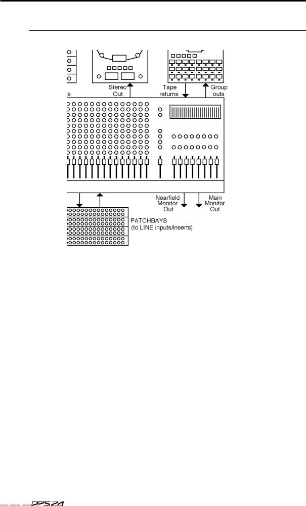
Internally, the DPS24 is laid out much like any conventional recording studio:
At the heart of this 'typical' studio is a large, multi-channel mixer.
This mixer has 46 channels: 12 mono + 1 stereo inputs, 24 track returns and 4 stereo FX returns.
The mixer's 8 GROUP outputs are connected to the inputs of the MTR (multi-track recorder) and inputs are routed to tracks on the MTR via these. The outputs of the MTR are fed back into the mixer where the tracks can be mixed, EQ'd, etc.. Microphones are connected to bal anced mic inputs on the mixer and line sources are patched to the line inputs. The effects sends are connected to the effects processors and the outputs of these are connected to the mixer's effects return channels.
The mixer's stereo L/R outputs are connected to a stereo mastering machine. The outputs of the stereo recorder can be patched through a mastering compressor/expander, before feed ing a CD recorder (not shown here).
Monitor outputs feed an amplification system and, as is common in high-end studios, there are two monitor outputs - one feeds the control room's main monitoring system whilst an other feeds a smaller monitoring system (maybe a domestic hi-fi) for checking a mix on smaller speakers. Also in this typical studio (but not shown here) would be compressors, noise gates and so forth.

3
If you are familiar with this setup, then you already understand most of the DPS24 as this is pretty much what the DPS24 offers!
However, instead of separate analog units, all the above is done digitally within the DPS24 so that you enjoy the benefits of superior sound quality, automated mixing, non-destructive editing and much more besides in one convenient unit.
The obvious benefit of the DPS24 versus individual components is the simplification of the cabling between components. No need for expensive "snakes" between the mixer and the recorder, etc. All the cabling required is the connection from the sources and to the monitors.
Another advantage is that the data and parameters of all included components are stored
together, on the hard drive, in a single file for each song, called a PROJECT.
When loading a Project, the whole system is recalled in a single operation: audio tracks, edits, routing, mixer (levels, EQ, ...) and automation, effects settings.
In the same way, when Projects are backed-up or restored (which can be done via CD-R, SCSI or USB), the data for the whole system is included.
This reference manual covers the general operation of the various components included in the DPS24.
Take a little time to look at the control panel and get familiar with the various keys and controls of the surface.
As you will see, everything in the DPS24 is laid out very logically:
The Multi-Track recorder/editor is controlled using the 24 RECORD/EDIT SELECT keys for arming/editing the 24 Tracks and the full TRANSPORT section, including the GOTO and MEMORY keys for auto-locate functions, as well as the JOG/SHUTTLE wheel for audio scrubbing. A scrolling graphic view of the 24 tracks is displayed using the GRID key (SHIFT+MAIN SCREEN).
The Editing functions are accessed via the EDIT/DSP mode key and the Virtual Tracks via the V.TRACK key (SHIFT+PROJECT).
The Mixer section is controlled using the FADER BANK keys, the Faders, Channel ON keys (for Mute/Solo) and Channel SELECT keys, the Q-CHANNEL/Q-STRIP encoders and keys, the MIX SCENE STORE and RECALL keys, and of course, the MIXER key.
The Automation is accessed via .... the AUTOMATE key.
The Patch Bay is controlled using the ASSIGN L/R and GROUP keys, and of course, the PATCH key (SHIFT+MIXER)
The Effects are accessed via.... the FX key.
Projects are managed in the PROJECT mode.
Global Project settings are accessed via the SETUP key.
Finally, Audio CD writing functions are accessed via the CD-R key (SHIFT+SETUP).
The detailed operation of all those controls is described is this manual.
Recording via Groups is only the default configuration of the DPS24. However, if you are not familiar with 8-buss recording operation, the routing of the DPS24 can be changed to bypass the groups, by patching inputs directly to tracks. Please refer to the PATCH mode for more details.
4 REAR PANEL
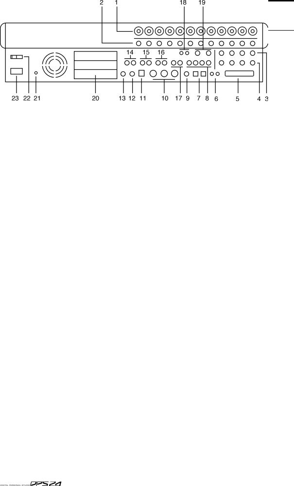
REAR PANEL
The rear panel has a comprehensive selection of connectors to interface the DPS24 with a wide range of analogue and digital equipment. These are:
1. INPUTS - BANK A
Across the top of the rear panel are the two banks of analog inputs. The top row (Bank A) are balanced inputs on XLR/TRS jack combos. These can accommodate XLR connectors or TRS (tip, return, send - stereo) 1/4" jack plugs.
2. INPUTS - BANK B
The second row of inputs (Bank B) are TRS jacks that can accommodate balanced inputs. Banks A and B are switched from the front panel using the switches across the top of the panel
3.CHANNEL INSERT SENDS/DIRECT OUT
4.CHANNEL INSERT RETURNS/ADC INPUTS
Inputs 1-4 also feature balanced insert points allowing you to patch in professional external processors such as noise gates, compressors, etc.. Although each channel of the DPS24 has a compressor/gate, you may want to use external valve units or other devices.
The channel insert sends (3) can also be used as balanced direct outputs and the channel insert returns (4) can also be used to accept external pre-amps or 19" 'channel strips' therefore by-passing the internal pre-amps on the DPS24 for these channels.
5. SCSI CONNECTOR OPTION
The optional 68pin Wide-SCSI interface IB-24SCSI may be installed here allowing you to connect external SCSI drives to the DPS24.
6. DIGITAL I/O
These RCA phono connectors offer SPDIF digital audio input and output. The input is freely assignable to channels within the DPS24 and the output can accept a wide variety of internal audio sources (the default is the master stereo L/R output).
7. MULTI-PURPOSE LIGHT PIPE I/O
These optical connectors can be configured to carry either stereo SPDIF or 8-channel ADAT˛ digital input/output.
8. AUXILLIARY SENDS 1-4
AUX SENDS 1-4 default to being output here for use with external effects processors. How-

REAR PANEL |
5 |
ever, it is possible to patch other audio sources to appear at these outputs if you wish.
9. WORDCLOCK I/O
When wordclock is selected as the sync source, this BNC is set to receive wordclock. At all other times, this BNC is set to generate wordclock.
10. MIDI IN/OUT/THRU
The MIDI IN connection can accept MIDI Time Code for synchronising to external equipment such as sequencers.
The MIDI OUT connector can generate MIDI Time Code or MIDI Clock so that sequencers, etc., may be synchronised to the DPS24. The MIDI OUT can also generate MIDI Controller events such as volume and pan allowing the DPS24 to control (mix) external equipment (for example, samples, sound modules, etc.).
The MIDI THRU connection passes MIDI data received at the MIDI Input.
11. USB CONNECTOR
This is provided for connection to a personal computer using the akSys TrackView software or the akSysServer audio file transfer utility.
12. PS2 KEYBOARD CONNECTOR
You may attach a PS2 keyboard here to assist with naming items in the DPS24.The key mapping of the keyboard to DPS24 functions is shown in the appendix section.
13. FOOTSWITCH INPUT
This 1/4" jack socket can accept a footswitch for hands-free recording and playback of the DPS24. This input can also accept an Alesis LRC˛ remote controller allowing simple remote control (when overdubbing vocals in a separate studio are or vocal booth, for example).
The key mapping of the LRC to DPS24 functions is shown in the appendix section.
14. MASTER STEREO OUTPUT
These balanced outputs should be connected to the line inputs of your stereo mastering machine.
15. MAIN MONITOR OUTPUT
These balanced outputs should be connected to the line inputs of your main control room monitor amplifier or powered speakers.
16. NEARFIELD MONITOR OUTPUT
These balanced outputs should be connected to the line inputs of a smaller monitoring system powering smaller speakers. You may switch between the MAIN and NEARFIELD monitoring systems using the NEAR switch in the monitoring section of the DPS24's control surface.
17. STUDIO FOLDBACK OUTPUTS
These outputs should be connected to a separate monitoring system (typically an amplified headphone monitoring system) located in a separate studio recording area , vocal booth, etc.. The audio feed to these outputs is derived via AUX 3/4 allowing an independent mix to be sent to these outputs when track laying and overdubbing.
NOTE: When either of the STUDIO OUTPUTS are enabled, the respective AUX out put (3 and/or 4) is disabled. This is selected in the MIXER / FX/AUX SETUP page.
18. 2-TRACK INPUT
You should connect the outputs of your stereo mastering machine to these RCA phonos. You can monitor this input using the 2-TRACK switch found in the monitoring section of the DPS24's control surface. However, the 2-TRACK input can also be freely patched within the DPS24 and used as a record source if you wish.
 v1.6 Operator s Manual

6REAR PANEL
19.AUX IN
This is a balanced stereo input that can be used for a variety of purposes. It can be used to bring in an external sub-mixer (for example, to expand the number of input channels for sound modules, samplers, drum machines, etc., that may be being sequenced during mixdown) or it can be used as a stereo effects return. By default, this signal feeds the main L/ R bus via the stereo AUX mixer channel prior to the master stereo fader. However, the AUX IN can also be freely patched within the DPS24 and used as a record source if you wish.
20. EXPANSION SLOTS
These three slots can be used to accept a variety of optional expansion cards, such as:
*IB-24ADT : ADAT˛ Expansion card, adding 16 more channels of ADAT˛ digital input output and an ADAT˛ SYNC OUT connector to control the transports of ADAT˛ machines from the DPS24.
*IB-24LTC : SMPTE/EBU Time Code Reader/Generator card for synchronization with other devices such as Tape machines and Video decks.
*The third expansion slot is reserved for future options.
21.GROUND TERMINAL
Connect this to some earthed metalwork if you experience any mains hum or interference as it may help reduce it.
22. POWER SWITCH
This is used to switch the DPS24 on and off.
23. POWER CONNECTOR
This should be attached to a suitable cable connected to a mains power source.
 v1.6 Operator s Manual
FRONT PANEL |
7 |
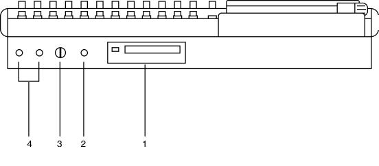
FRONT PANEL
1. CD-RW/CD-R DRIVE BAY
An IDE CD-RW is installed here.
It is also possible to install a removable IDE hard drive bay.
2. HI-Z GUITAR INPUT
An electric guitar (or bass guitar) may be DI'd into this high impedance input.
Note that when a jack is plugged into this input, it uses Input Channel 12, and Inputs 12A and 12B on the rear panel are overridden and cannot be used.
3. HEADPHONE LEVEL
This allows control of the level of the signal appearing at the headphone outputs.
4. HEADPHONE OUTPUT
Two headphone output connectors are provided. Both are identical (i.e. wired in parallel) and carry a duplicate of the MONITOR output.
 v1.6 Operator s Manual

8 Top Panel
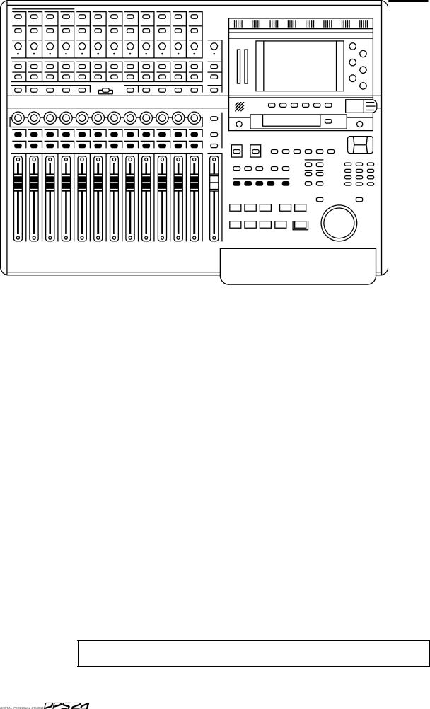
TOP PANEL
GETTING AROUND THE DPS24
This section deals with the DPS24's control surface. Although we would like to think that most of it should be fairly self-explanatory, please read this section to gain a full understand ing of the DPS24's functions.
The panel is laid out logically with many dedicated keys that provide direct access to the most commonly used functions employed when recording, track laying, overdubbing and mixing and the DPS24's control surface is designed in such a way that for every day use, it should not be necessary to access obscure, LCD-driven menus - with its 'knobby' front panel, operation is designed to be as 'hands-on' and 'traditional' as possible. For example....
For track laying, route the inputs to the appropriate track(s) using the Group function as on a traditional mixer, arm the track(s) for record and press PLAY and RECORD together. Drop out of record by pressing PLAY again. To overdub, rewind, re-group, select different tracks for record and repeat the process, monitoring previously recorded material via the DISK TRACKS fader bank.
Want to pan your tracks? Simply use the row of encoders above the faders. Want to add effects? Select the appropriate FX send in the Q-STRIP FUNCTION panel and adjust the encoders to set FX send levels as necessary.
Need to tweak EQ? Select the appropriate channel(s) using the channel SELECT keys, press the Q-CHANNEL key and adjust the EQ using the Q-CHANNEL encoders.
Need to tweak an effect? Press FX and use the Q-LINK controls to modify parameters (and with the Q-CHANNEL selected, you can adjust the channel parameters AND the effects pa rameters simultaneously).
If you are working with artists in separate rooms, set up a 'foldback' cue mix using pre-fade AUX 3 and/or 4 and the STUDIO outputs - even speak to them via the DPS24's internal talkback mic during the track laying process.
Having laid down some tracks, you hear something that needs deleting! Simply hit EDIT, select the appropriate track(s), mark the offending region with the IN/OUT keys and press CUT or ERASE. Similarly, you want to use that one great guitar riff elsewhere in the project - select the appropriate track(s), press EDIT, mark the region, copy it and paste it wherever it's needed.
You get the picture!
And so far, unlike other digital mixers/recorders, all of this is achieved without hardly ever having to refer to the LCD!
To find out more, read on.
ILLUMINATED KEYS
Illuminated keys will light when selected as you would expect.
However, in certain circumstances, these keys flash to indicate that they are in a different status. For instance, the CH ON keys are lit when mixer channels are ON (not muted), but they flash when the mixer channels are solo'ed.
Also, the RECORD/EDIT SELECT keys for the 24 tracks use bi-color LEDs, red for Record
(flashing when ready, lit when recording) and green for Edit,
INPUTS 9
INPUTS
Across the top of the panel are controls associated with the twelve analog input preamps.
The functions are:
48V ON/OFF |
Switches on 48 volt phantom power to Inputs A 1-4 allowing these chan |
|
nels to be used with condenser mics. |
A/B |
The switches running along the top switch between Input A or B. |
|
(A is the XLR combo, B is the 1/4" jack) |
LINE/MIC The next row of switches set the input (TRIM) sensitivity between line ( 15dB <> +45dB) and mic (0dB <> +60dB).
TRIM |
This pot allows you set the input channel's initial gain according to the |
|
setting of the LINE/MIC switch. |
SIG/CLIP This tri-coloured LED shows the level of the input signal after the input pre-amp. It illuminates as follows:
-60dB or less |
OFF |
-60dB -> -3dB |
GREEN |
-3dB |
YELLOW |
0dB |
RED (clip) |
10 Top Panel
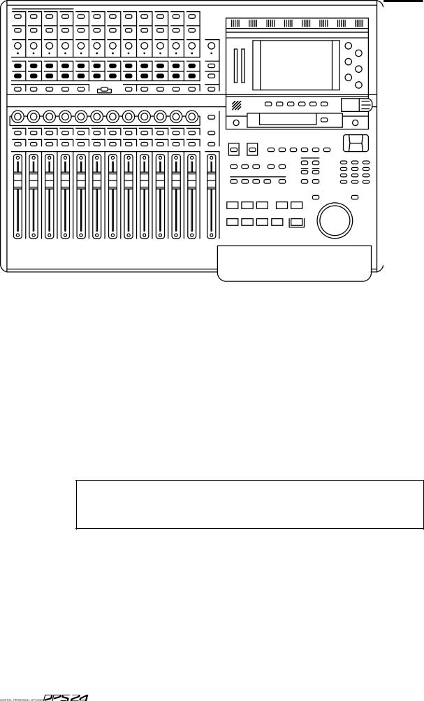
RECORD/EDIT SELECT KEYS
Below the inputs are the RECORD/EDIT SELECT keys for Tracks1-24:
These keys have bi-coloured LEDs and normally, when recording, they illuminate red and are used to select tracks for record. However, when the EDIT mode is enabled, these keys illuminategreen and are used to select tracks for editing.
The number shown to the right of each key shows the default Group assignment. As on a 'traditional' console/recorder combination, the group outputs are patched to the disk tracks and channels are routed to them by way of the Groups (Groups 1-8 routed to Tracks 1-8, 9-16 and 17-24). So, for example, to route Input 5 to Track 3, you would assign it to GROUP 3/4. To route, say, Tracks 1, 2, 3 and 4 to, say, Tracks 13 and 14 for a stereo bounce-down, you would assign them all to GROUP 5/6.
Because of the flexible patching facilities in the DPS24, it is possible to override the default group routing arrangement so the default assignment shown alongside the record track numbers may not be applicable if you have changed them. Routing and patching is explained in more detail later in this manual.
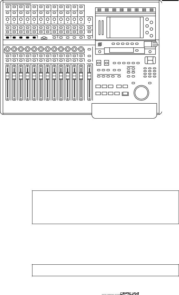
L/R AND GROUP ASSIGN KEYS 11
L/R AND GROUP ASSIGN KEYS
Below the RECORD/EDIT SELECT keys to the left of the panel are the ASSIGN keys:
These allow you to route signals to the groups and also to the stereo L/R bus.
To route any channel to a Group (and hence to the track(s)), press the desired GROUP key. The current GROUP key will flash. The SELECT keys for any channels assigned to that group will illuminate whilst those that aren't assigned will flash. Press the channel SELECT keys for the channels you wish to assign (or press an illuminated key to de-assign a channel).
When done, press the GROUP key again to return to normal mode. The GROUP key will stop flashing.
If a channel SELECT key is not lit nor flashing, it means that the channel in question cannot be routed to that bus. This applies to GROUP, AUX and MIDI mixer channels.
Almost any channel can be assigned to any group. However, it is not possible to assign groups to groups. Groups can be assigned to the stereo L/R bus, however.
In normal operation, i.e. when not assigning channels to groups, the GROUP keys should not be flashing.
To assign a channel to the L/R output bus, press the L/R key. The L/R key will flash.The SELECT keys for any channels assigned to the L/R bus will illuminate (and those that aren't will flash).
Press the channel SELECT keys for the channels you wish to assign (or press an illuminated key to de-assign a channel).
When done, press the L/R key again to return to normal mode. The L/R key will stop flashing.
In normal operation, i.e. when not assigning channels to the L/R bus, the L/R key
should not be flashing.

12 Top Panel
SUB-GROUPING CHANNELS TO THE L/R MIX
Very often (especially during mixdown), it is very useful to be able to sub-group certain channels to the stereo L/R bus via the Groups. For example, all your drums and percussion channels could be sub-grouped to one group, all your keyboard parts to another, all your backing vocals to another, etc., so that you have control over these elements with a single Group fader.
Routing groups to the stereo L/R bus is done simply by pressing the L/R key and, in the
GROUPS/FX fader bank, pressing the group channels' (1-8) SELECT key(s) as appropriate. This is consistent with assigning other channels to groups.
Channels which are routed to a sub-group need to be taken out of the stereo L/R bus to avoid them appearing twice. - once through the direct connection of the channel to the stereo L/R bus and secondly through its connection to the stereo L/R bus via the subgroup.
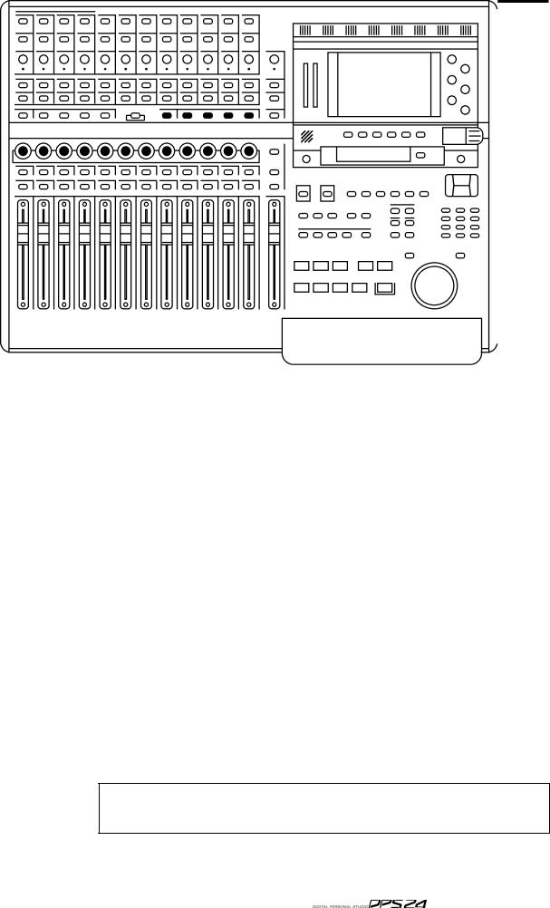
Q-STRIP FUNCTION KEYS/CHANNEL ENCODERS 13
Q-STRIP FUNCTION KEYS/CHANNEL ENCODERS
Below the RECORD/EDIT SELECT keys to the left of the panel are the Q-CHANNEL key and the Q-STRIP FUNCTION keys:
Directly above the channel faders is a row of continuous rotary encoders (the Q-STRIP / Q CHANNEL) with a 'collar' of LEDs around each of them that serve a variety of purposes.
When the Q-CHANNEL key is off, they operate as the Q-STRIP.
On power up, their default function is to act as PAN controls with one pan control for each of the channels of the current Fader Bank.
However, they may be used to set FX/AUX send levels.
This functionality is selected using the Q-STRIP FUNCTION keys:
PAN : Sets the rotary encoders to act as pan controls for each of the channels.
FX/AUX 1-4 : Sets the rotary encoders to act as send levels for the internal effects channels or to the AUXILIARY bus.
If the sends are configured as stereo sends, FX/AUX1 sets the send level and FX2 sets the pan position. The same is true for FX/AUX3/4 - if set to stereo, FX/AUX3 sets the level and FX/AUX4 sets panning.

14 Top Panel
FADER FLIP
It is also possible to 'flip' (or swap) the faders and FX/Aux sends allowing you to set FX/ Aux sends using the motorized faders. This is useful when you require very abrupt changes to FX/Aux sends... to allow for precision when setting the FX/Aux send levels, the encoders need a few turns to cover the entire range. The faders, on the other hand, can cover the entire range in one swift movement.
To flip the faders, simply 'double-click' the FX/Aux buttons:
Press the FX/Aux key once to select it. Press it again to 'flip'.
When 'flipped, the faders set FX/Aux send level and the encoders now set channel level.
When 'flipped', the LED in the key will flash to indicate its status.
Press it again to return to normal operation.
If the sends are configured as stereo sends, when FX/AUX1 is 'flipped', the faders set FX/ Aux1/2 send level and the encoders set the channel level.
However, when FX/AUX2 is 'flipped', the faders set FX/Aux1/2 send level and the encoders set FX/ AUX1/2 send pan position. The same is true for FX/AUX3/4.

Q-CHANNEL SELECT / Q-CHANNEL ENCODERS 15
Q-CHANNEL SELECT/Q-CHANNEL ENCODERS
In the centre of the panel is the Q-CHANNEL key:
One of the most useful features of the DPS24 is that the row of encoders directly above the faders can be switched to become a complete channel's worth of parameters allowing you to have 'hands-on' control of panning, EQ and FX/Aux sends. This 'mode' is enabled by press ing the Q-CHANNEL switch located centrally on the upper panel.
When the Q-CHANNEL key is on (illuminated), the encoders function as a complete channel strip for the selected Channel as follows from left to right (as labelled underneath the encoders):
PAN
LOW SHELF EQ FREQUENCY
LF GAIN
SWEEP EQ FREQUENCY
SWEEP EQ GAIN
SWEEP EQ 'Q'
HIGH SHELF EQ FREQUENCY1
HF GAIN
FX/AUX 1 SEND LEVEL
FX/AUX 2 SEND LEVEL
FX/AUX 3 SEND LEVEL
FX/AUX 4 SEND LEVEL

16 Top Panel
Furthermore, the function of the Q-STRIP FUNCTION keys described earlier also change when the Q-CHANNEL is enabled:
The labelling underneath the keys denotes their function when in Q-CHANNEL 'mode' and you have 'hands-on' control to bypass the EQ and to switch FX/AUX 1-4 as preor post-fade.
Of course, for the Q-CHANNEL 'mode' to be applicable, you must select a channel for edit ing (i.e. you should press a channel's SELECT key just under the row of encoders). The SE LECT key of the selected Channel is illuminated. On power up, the default selection is the Master Channel.
Enabling Q-CHANNEL automatically calls up the MIXER / CHANNEL page of the selected Channel on the LCD. Then , when disabling Q-CHANNEL, the display returns to the previous screen.
Q-STRIP / Q-CHANNEL ENCODERS 17
Q-STRIP/Q-CHANNEL ENCODERS
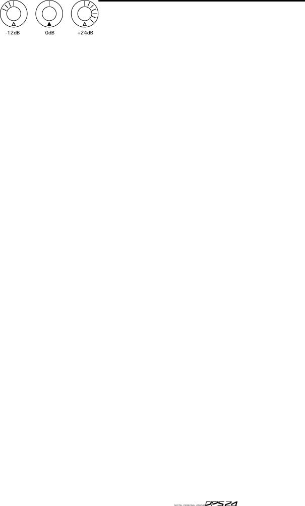
Around the encoders is a collar of LEDs that show the encoder's value. As the control is moved, so do these LEDs illuminate to show its position. However, the way these LEDs illuminate depend on the control's function.
PAN POSITION / EQ FREQUENCY
When used as a pan pot, the LEDs around the encoders illuminate as follows:
When the encoder is set to MID, the red LED at the bottom illuminates as well. This is to assist with viewing the encoder(s) at an angle where the top middle LED may not be visible.
LEVEL CONTROL
When the encoders are used as level controls (e.g. FX/AUX SEND), the LEDs illuminate as follows:
EQ GAIN
When the encoders are being used to set EQ gain in the Q-CHANNEL, the LEDs illuminate as follows:
EQ 'Q'
When the encoder is used to set EQ 'Q' in the Q-CHANNEL, its' LEDs illuminate as follows:
In this way, the control gives an almost graphic indication of the 'width' of the sweep EQ. With the control at minimum, the Q is at its widest; at maximum, the Q is at its narrowest.
18 Top Panel
FADERS/FADER BANKS
Below the DPS24's Q-STRIP/Q-CHANNEL encoders are the channel faders and SELECT and ON/SOLO keys:
Each channel is identical whether it's an input or a disk channel (the GROUP/FX channels are different and those differences are described on the next page). Each channel has a long throw 100mm motorised fader which is touch sensitive for use with the mixer's automation and simply touching the fader will make it active.
Channels may be muted using the green ON key above the fader.
When the channel is ON, the key illuminates; when it is OFF (muted), the key is not lit.
By pressing SHIFT+ON, the channel can be solo'd.
When a channel is solo'd, the ON key's LED flashes (and a large SOLO LED flashes in the
MASTER section). SOLO operation is described later in the manual.
A channel can be selected for tweaking using the channel SELECT key above each fader.
The SELECT keys are also used in conjunction with the ASSIGN keys to route channels to the L/R bus and/or to Groups (and hence to disk tracks) for recording.
The SELECT keys can be used to link adjacent odd/even Channels as a stereo pair.
To link a pair of channels, press the SELECT key of one of the channels while holding down the SELECT key of the adjacent channel. To un-link them, use the same procedure.
Once linked, pressing the SELECT key for either channel will select both, and the ON key of
either channel will be used for muting/solo'ing both channels.
Only odd/even adjacent channels can be paired., not even/odd channels, i.e. you can link channels 1&2 or 3&4, but not channels 2&3.
Loading...