


DR16 PRO
HARD DISK RECORDER
Operator’ s Manual
WARNING
To prevent fire or shock hazard, do not
expose this appliance to rain or moisture.
000218-4 Printed in Japan
Important Notice
The material in this document is copyright to AKAI professional M.I. Corp., and may not be
quoted or reproduced in any form without written permission from the company.
LIMITED SOFTWARE WARRANTY POLICY
All the software provided with, or purchased especially for, AKAI professional products has
been tested for functionality. AKAI professional M.I. Corp. will make its best efforts to correct
reported software defects for future releases subject to technical practicabilities.
AKAI professional M.I. Corp., makes no warranty or representation either expressed or
implied with respect to the system's performance or fitness for a particular purpose.
In no event will AKAI professional M.I. Corp. be liable for direct or indirect damages arising
from any defect in the software or its documentation. Further, AKAI professional M.I. Corp.
will not accept any liability for any programs, sounds, audio recording or sequences stored in
or used with AKAI professional products, including the cost of recovery of such data.
The warranties, remedies and disclaimers above are exclusive and take precedence over all
others, oral or written, express or implied, to the extent permitted by law in the geographical
area of the product's use. No employee of AKAI professional M.I. Corp., agent, distributor or
employee of an agent or distributor is authorised to offer any variation from this policy.
WARNING!!
To prevent fire or shock hazard, do not expose this appliance to rain or moisture.
CAUTION
RISK OF ELECTRIC SHOCK
DO NOT OPEN
CAUTION: TO REDUCE THE RISK OF ELECTRIC SHOCK
DO NOT REMOVE COVER (OR BACK).
NO USER-SERVICEABLE PARTS INSIDE.
REFER SERVICING TO QUALIFIED SERVICE PERSONNEL.
THE SYMBOLS ARE RULED BY UL STANDARDS (U.S.A.)
The lightning flash with arrowhead symbol , within an equilateral triangle, is
intended to alert the user to the presence of uninsulated “dangerous voltage”
within the product’s enclosure; that may be of sufficient magnitude to
constitute a risk of electric shock to persons.
The exclamation point within an equilateral triangle is intented to alert the user
to the presence of important operating and maintenance (servicing) instructions in the literature accompanying the appliance.
1-En
5A-En
Lithium battery
This product uses a lithium battery for memory backup.
The lithium battery should only be replaced by qualified service personnel.
Improper handling may cause risk of explosion.
Page i
24A-En

WARNING
WARNING
The DR16pro is designed to be used in a standard household environment.
Power requirements for electrical equipment vary from area to area. Please ensure that your
DR16pro meets the power requirements in your area. If in doubt, consult a qualified electrician or
AKAI professional dealer.
120VAC @ 60Hz for USA and Canada
220-230/240VAC @ 50Hz for Europe
240VAC @ 50Hz for Australia
PROTECTING YOURSELF AND THE DR16pro
Never touch the AC plug with wet hands.
•
Always disconnect the DR16pro from the power supply by pulling on the plug, not the cord.
•
Allow only an AKAI professional dealer or qualified professional engineer to repair or reas-
•
semble the DR16pro. Apart from voiding the warranty, unauthorized engineers might touch live
internal parts and receive a serious electric shock.
Do not put, or allow anyone to put any object, especially metal objects, into the DR16pro.
•
Use only a household AC power supply. Never use a DC power supply.
•
If water or any other liquid is spilled into or onto the DR16pro, disconnect the power, and call
•
your dealer.
Make sure that the unit is well-ventilated, and away from direct sunlight.
•
To avoid damage to internal circuitry, as well as the external finish, keep the DR16pro away
•
from sources of direct heat (stoves, radiators, etc.).
Avoid using aerosol insecticides, etc. near the DR16pro. They may damage the surface, and
•
may ignite.
Do not use denaturated alcohol, thinner or similar chemicals to clean the DR16pro. They will
•
damage the finish.
Modification of this equipment is dangerous, and can result in the functions of the DR16pro
•
being impaired. Never attempt to modify the equipment in any way.
In order to assure optimum performance of your DR16pro, select the setup location carefully,
•
and make sure the equipment is used properly. Avoid setting up the DR16pro in the following
locations:
1. In a humid or dusty environment
2. In a room with poor ventilation
3. On a surface which is not horizontal
4. Inside a vehicle such as a car, where it will be subject to vibration
5. In an extremely hot or cold environment
Page ii

Precautions When Using the Installed Hard Disk Drive
1. The hard disk drive has extremely high precision and is vulnerable to shock and vibration. If
transporting the DR16pro by either land or air, we recommend packing it in a shell-shaped
case lined with urethane rubber which meets ATA specifications.
2. Make sure the DR16pro is used in the horizontal position. Do not set it on end or tilt it when
using it.
3. If the DR16pro is moved from a cold location to a warm one, or if the temperature has been
raised suddenly, condensation may form inside the DR16pro. If it is impossible to avoid conditions like these, let the DR16pro sit for at least an hour in the new location before using it.
4. When setting up the DR16pro, make sure the ventilation opening is not blocked. Also, if using
the DR16pro in a rack that contains other equipment, make sure sufficient ventilation space is
assured on all sides (approx. 44 mm of space between the DR16pro and any equipment
mounted above or below it in the rack).
Page iii

WARNING
THIS APPARATUS MUST BE EARTHED
IMPORTANT
This equipment is fitted with an approved non-rewireable UK mains plug.
To change the fuse in this type of plug proceed as follows:
1) Remove the fuse cover and old fuse.
2) Fit a new fuse which should be a BS1362 5 Amp A.S.T.A or BSI approved type.
3) Refit the fuse cover.
If the AC mains plug fitted to the lead supplied with this equipment is not suitable for
your type of AC outlet sockets, it should be changed to an AC mains lead, complete
with moulded plug, to the appropriate type. If this is not possible, the plug should be
cut off and a correct one fitted to suit the AC outlet. This should be fused at 5 Amps.
If a plug without a fuse is used, the fuse at the distribution board should NOT BE
GREATER than 5 Amp.
PLEASE NOTE: THE SEVERED PLUG MUST BE DESTROYED TO AVOID A
POSSIBLE SHOCK HAZARD SHOULD IT BE INSERTED
INTO A 13 AMP SOCKET ELSEWHERE.
The wires in this mains lead are coloured in accordance with the following code:
GREEN and YELLOW — EARTH
BLUE — NEUTRAL
BROWN — LIVE
As the colours of the wires in the mains lead of this apparatus may not correspond
with the coloured markings identifying the terminals in your plug, please proceed as
follows:
The wire which is coloured GREEN and YELLOW must be connected to the
terminal which is marked with the letter E or with the safety earth symbol or
coloured GREEN or coloured GREEN and YELLOW.
The wire which is coloured BLUE must be connected to the terminal which is
marked with the letter N or coloured BLACK.
The wire which is coloured BROWN must be connected to the terminal which is
marked with the letter L or coloured RED.
THIS APPARATUS MUST BE EARTHED
Ensure that all the terminals are securely tightened and no loose strands of wire
exist.
Before replacing the plug cover, make certain the cord grip is clamped over the
outer sheath of the lead and not simply over the wires.
6D-En
Page iv
FCC WARNING
This equipment has been tested and found to comply with the limits for a Class B digital
device pursuant to Part 15 of the FCC rules. These limits are designed to provide reasonable protection against harmful interference in a residential installation. This equipment
generates, uses, and can radiate radio frequency energy and, if not installed and used in
accordance with the instructions, may cause harmful interference to radio communications.
However, there is no guarantee that interference will not occur in a particular installation. If
this equipment does cause harmful interference to radio or television reception, which can
be determined by turning the equipment off and on, the user is encouraged to try to correct
the interference by one or more of the following measures:
- Reorient or relocate the receiving antenna.
- Increase the separation between the equipment and receiver.
- Connect the equipment into an outlet on a circuit different from that to which the receiver is
connected.
- Consult the dealer or an experienced radio/TV technician for help. 21B-En
CHANGES OR MODIFICATIONS NOT EXPRESSLY APPROVED BY THE MANUFACTURER FOR
COMPLIANCE COULD VOID THE USER’S AUTHORITY TO OPERATE THE EQUIPMENT.
32-En
AVIS POUR LES ACHETEURS CANADIENS DU DR16pro
Le présent appareil numérique n’ément pas des bruits radioélectriques dépassant les limites
applicables aux appareils numériques de la Class B prescrites dans le Règlement sur le
brouillage radioélectrique édicté par le ministère des Communications du Canada
27-F
This digital apparatus does not exceed the Class B limits for radio noise emissions from
digital apparatus set out in the Radio Interference Regulations of the Canadian Department of Communications.
27-En
VENTILATION
Do not prevent the unit's ventilation, especially by placing the unit on the soft carpet, in a narrow space,
or by placing objects on the unit's chassis—top, side, or rear panels. Always keep the unit's chassis
at least 10 centimeters from any other objects.
31C-En
COPYRIGHT NOTICE
The AKAI DR16pro is a computer-based device, and as such contains and uses software in ROMs.
This software, and all related documentation, including this Owner’s Manual, contain proprietary
information which is protected by copyright laws. All rights are reserved. No part of the software or
its documentation may be copied, transferred or modified. You may not modify, adapt, translate,
lease, distribute, resell for profit or create derivative works based on the software and its related
documentation or any part there of without prior written consent from AKAI professional M.I. Corp.,
Yokohama, Japan.
Page v

WARRANTY
AKAI professional M.I. Corp. warrants its products, when purchased from an authorized AKAI professional
dealer, to be free from defects in materials and workmanship for a period of 12 (twelve) months from the date
of purchase. Warranty service is effective and available to the original purchaser only , and only on completion
and return of the AKAI professional Warranty Registration Card within 14 days of purchase.
Warranty coverage is valid for factory-authorized updates to AKAI professional instruments and their software,
when their installation is performed by an authorized AKAI professional Service Centre, and a properly
completed Warranty Registration has been returned to your AKAI professional dealer.
To obtain service under this warranty, the product must, on discovery of the defect, be properly packed and
shipped to the nearest AKAI professional Service Centre. The party requesting warranty service must provide
proof of original ownership and date of purchase of the product.
If the warranty is valid, AKAI professional will, without charge for parts or labour, either repair or replace the
defective part(s). Without a valid warranty, the entire cost of the repair (parts and labour) is the responsibility
of the product’s owner.
AKAI professional warrants that it will make all necessary adjustments, repairs and replacements at no cost
to the original owner within 12 (twelve) months of the purchase date if:
1 The product fails to perform its specified functions due to failure of one or more of its components.
2 The product fails to perform its specified functions due to defects in workmanship.
3 The product has been maintained and operated by the owner in strict accordance with the written
instructions for proper maintenance and use as specified in this Operator’s Manual.
Before purchase and use, owners should determine the suitability of the product for their intended use, and
the owner assumes all risk and liability whatsoever in connection therewith. AKAI professional shall not be
liable for any injury, loss or damage, direct or consequential, arising out of the use, or inability to use the
product.
The warranty provides only those benefits specified, and does not cover defects or repairs needed as a result
of acts beyond the control of AKAI professional, including, but not limited to:
1 Damage caused by abuse, accident or negligence. AKAI professional will not cover under warranty any
original factory disk damaged or destroyed as a result of the owner’s mishandling.
2 Damage caused by any tampering, alteration or modification of the product: operating software,
mechanical or electronic components.
3 Damage caused by failure to maintain and operate the product in strict accordance with the written
instructions for proper maintenance and use as specified in this Operator’s Manual.
4 Damage caused by repairs or attempted repairs by unauthorized persons.
5 Damage caused by fire, smoke, falling objects, water or other liquids, or natural events such as rain,
floods, earthquakes, lightning, tornadoes, storms, etc.
6 Damage caused by operation on improper voltages.
IMPORTANT NOTE: This warranty becomes void if the product or its software is electronically modified,
altered or tampered with in any way.
AKAI professional shall not be liable for costs involved in packing or preparing the product for shipping, with
regard to time, labour or materials, shipping or freight costs, or time and expenses involved in transporting
the product to and from an AKAI professional Authorized Service Centre or Authorized Dealer.
AKAI professional will not cover under warranty an apparent malfunction that is determined to be user error,
or the owner’s inability to use the product.
THE DURATION OF ANY OTHER WARRANTIES, WHETHER IMPLIED OR EXPRESS, INCLUDING BUT
NOT LIMITED TO THE IMPLIED CONDITION OF MERCHANTABILITY, IS LIMITED TO THE DURATION
OF THE EXPRESS WARRANTY HEREIN.
AKAI professional hereby excludes incidental or consequential damages, including but not limited to:
1 Loss of time
2 Inconvenience
3 Delay in performance of the Warranty
4 The loss of use of the product
5 Commercial loss
6 Breach of any express or implied warranty, including the lmplied W arranty of Merchantability, applicable
to this product
Page vi

Contents
Contents
Introduction ....................................................................................................... 1
What is the DR16pro?........................................................................................................ 1
Signal Flow ........................................................................................................................ 3
Level Diagram.................................................................................................................... 5
Inside the DR16pro ............................................................................................................ 6
1 Front and Rear Panels ................................................................................................. 7
Front Panel ........................................................................................................................ 7
Rear Panel ....................................................................................................................... 18
2 Getting Around the DR16pro..................................................................... 23
Operating Modes ............................................................................................................. 23
Operation ......................................................................................................................... 24
Entering Time Values ....................................................................................................... 26
3 Setting Up the DR16pro............................................................................. 28
Typical DR16pro Setup.................................................................................................... 29
4 Recording ................................................................................................... 30
Sampling Frequency ........................................................................................................ 30
Input Source..................................................................................................................... 33
Selecting the Input Channels ........................................................................................... 35
Starting & Stopping Recording......................................................................................... 38
Punch-In Functions .......................................................................................................... 39
Recording Undo ............................................................................................................... 44
Setting the Recording Mode ............................................................................................ 45
5 Playback...................................................................................................... 47
Outputs ............................................................................................................................ 47
Starting & Stopping Playback .......................................................................................... 48
Starting & Stopping Playback by Footswitch ................................................................... 48
Special Play Keys ............................................................................................................ 49
Repeat ............................................................................................................................. 52
Varispeed ......................................................................................................................... 53
6 Projects ........................................................................................................ 54
Creating a New Project .................................................................................................... 54
Loading Project Files ....................................................................................................... 55
Deleting Project Files ....................................................................................................... 56
Creating a New Protools Session on a Macintosh disk ................................................... 58
7 Mixer............................................................................................................ 60
Output Assignment Mode................................................................................................. 60
Individual Channel Settings ............................................................................................. 61
System Settings ............................................................................................................... 65
Snapshot Settings............................................................................................................ 68
Mapping Snapshots ......................................................................................................... 69
Other Functions ............................................................................................................... 71
ADAT Digital Output......................................................................................................... 72
8 Take Functions ........................................................................................... 73
Other Take Applications ................................................................................................... 76
9 Locate Functions ....................................................................................... 77
Direct Locate Points (1 ~ 9 Keys) .................................................................................... 78
Page vii

Contents
Stack Locate Points ......................................................................................................... 79
Last Memory .................................................................................................................... 80
Preroll............................................................................................................................... 81
10 Time Display ............................................................................................. 82
Setting Relative Time to Zero........................................................................................... 83
Setting a Relative Time Offset ......................................................................................... 83
1 1 Editing ........................................................................................................ 84
Undoing an Edit ............................................................................................................... 85
Copy................................................................................................................................. 86
Copy+Insert .....................................................................................................................88
Move ................................................................................................................................ 89
Move+Insert .....................................................................................................................90
Insert ................................................................................................................................ 91
Erase................................................................................................................................ 92
Delete............................................................................................................................... 93
Slip ................................................................................................................................... 94
Slip Track ......................................................................................................................... 95
12 Hard Disks ................................................................................................. 96
SCSI................................................................................................................................. 97
Checking for Disks ......................................................................................................... 100
External Hard Disk Operating Precautions .................................................................... 101
Formatting Disks ............................................................................................................ 102
Erasing Disks ................................................................................................................. 104
Optimizing Your Hard Disks ........................................................................................... 105
Copying Disks and Projects ........................................................................................... 107
Data Compatibility with Akai 16 Bit DR8/DR16 Models ................................................. 109
13 Backup and Restore ................................................................................110
Backup ........................................................................................................................... 110
Restore .......................................................................................................................... 114
14 Synchronization ......................................................................................118
SMPTE/EBU Synchronization........................................................................................ 118
MIDI Synchronization..................................................................................................... 121
Master/Slave Operation Via RS422 ............................................................................... 123
15 Song Mode................................................................................................127
Creating a Song ............................................................................................................. 129
Creating a Tempo Map................................................................................................... 132
16 Other Functions .......................................................................................134
System Set up................................................................................................................ 134
Assigning AKAINET Machine ID .................................................................................... 134
Saving/Loading Settings to Flash ROM .................................................................. 135-136
Setting up for Using the MT8 Mixing Tab Unit................................................................ 140
SCMS............................................................................................................................. 141
Appendix.........................................................................................................142
Specifications................................................................................................................. 143
Options.................................................................................................................... 144-145
IB-808G Block Diagram ................................................................................................. 146
System Error Codes................................................................................................ 147-151
MIDI Implementation Chart ............................................................................................ 152
Index..........................................................................................................153-157
Page viii

Introduction
Introduction
From all at Akai, thank you for purchasing an Akai DR16pro Hard Disk Recorder, and welcome to
the exciting world of hard disk recording.
Please take the time to read this manual. It will allow you to get the best out of your DR16pro.
What is the DR16pro?
Take a conventional sixteen-track recorder, replace all the analog circuitry with the latest digital
audio processing technology, replace the tape transport with a hard disk for near-instant digital
audio data access, and add a 16-channel programmable digital mixer — the result is the DR16pro.
The DR16pro is a 16-track digital hard disk recorder and editor, with a built-in digital mixer. It
contains many of the features and functions you would normally expect, such as CD quality audio,
non-destructive editing, etc., but unlike computer-based systems, the DR16pro is as easy to use
as an ordinary multi-track tape recorder.
Features
16-track hard disk recorder with familiar multi-track recorder (MTR) operation.
•
16-channel programmable digital mixer with snapshot and fade automation.
•
24-bit 128-times oversampling A/D converters.
•
20-bit D/A 8-times oversampling on all outputs.
•
16-bit / 20-bit / 24-bit linear PCM recording.
•
Up to six SCSI hard disks can be connected.
•
96kHz sample rate support for DVD mastering.
•
Instant playback start.
•
Near-instant data access, no time consuming rewinds, etc.
•
Autolocator with 100 locate points.
•
Absolute and relative time modes, with sync offset.
•
Beat/tempo map for MIDI Clock synchronize operation.
•
MMC, MTC supported.
•
Adjustable preroll.
•
V arispeed playback.
•
Punch in/out includes: manual, auto (with rehearsal), and footswitch.
•
Jog/shuttle control for locating edits.
•
Take functions allow you to select from five different recordings.
•
Non-destructive editing functions include: copy, copy+insert, move, move+insert, erase, de-
•
lete, slip, insert, and edit undo.
Balanced 1/4 inch phone jack analog inputs and outputs.
•
Output mode is selectable for 16 individual channels or two stereo master and two send out-
•
puts.
XLR and RCA/phono digital inputs and outputs (AES/EBU or S/PDIF).
•
Backup to SCSI tape devices such as SCSI DAT or Exabyte.
•
Optional MT8 Mixing Tab for easier mixer setting.
•
Page 1

Introduction
Built in Ethernet (AKAINET) interface for connection to remote controllers.
•
Optional IB-802T SMPTE reader/generator board for time-code synchronization.
•
Optional IB-803M MIDI interface board for MIDI sequencer synchronization.
•
Optional IB-805R RS422 in terface board for master/slave operation via RS422.
•
Optional IB-1616A (IB-804A) ADAT interface board for digital data transfer between Alesis™
•
ADATs.
Optional EQ 16 digital EQ board.
•
Up to 4,000 audio files can be recorded on a disk. (DD-PLUS format)
•
A recording crossfade setting of 0-80ms is available.
•
An optional interface board IB-808G GPIO is available for track arming control.
•
An optional Multi-channel AES/EBU digital interface board IB-D16MA24 is available.
•
Flash ROM for system settings and OS updates.
•
TRADEMARKS
Digidesign and Protools are registered tademarks of Digidesign and/or A vid Technology, Inc.
Macintosh is a registered trademark of Apple Computer Inc. All other trademarks, product
and company names are the property of their respective owners.
Page 2
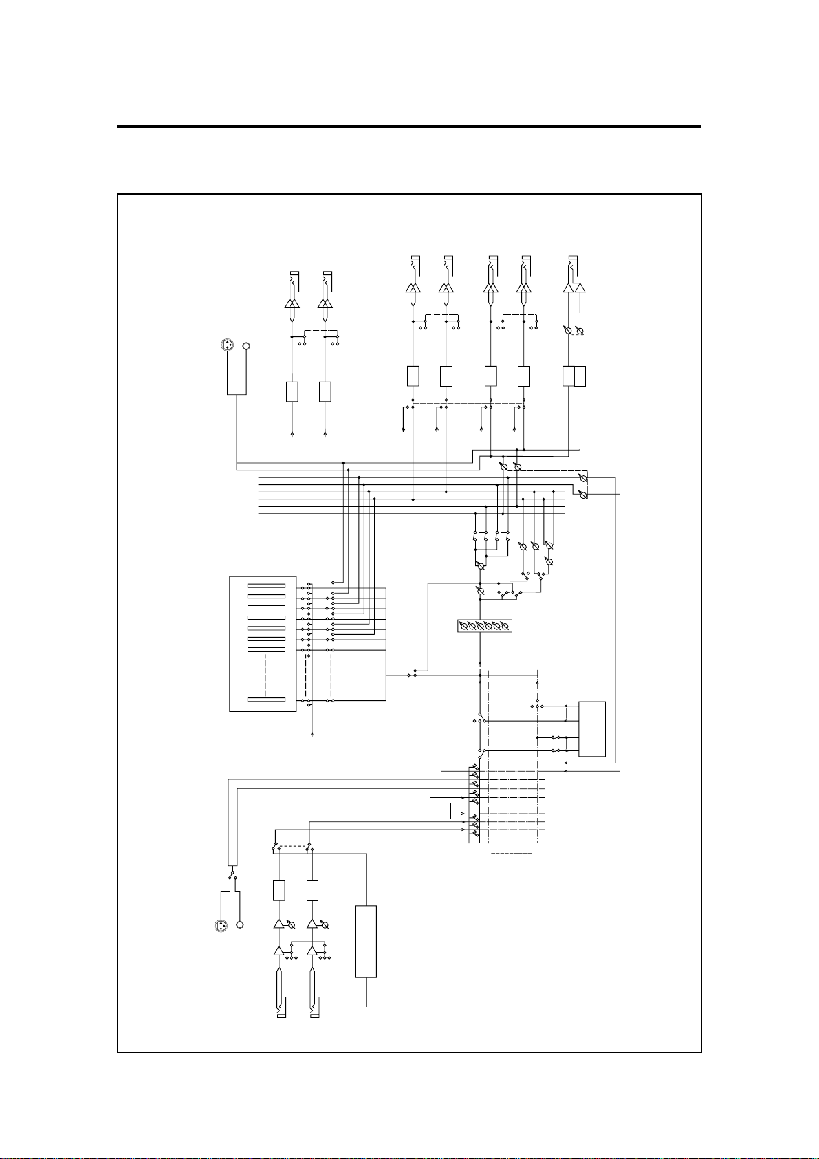
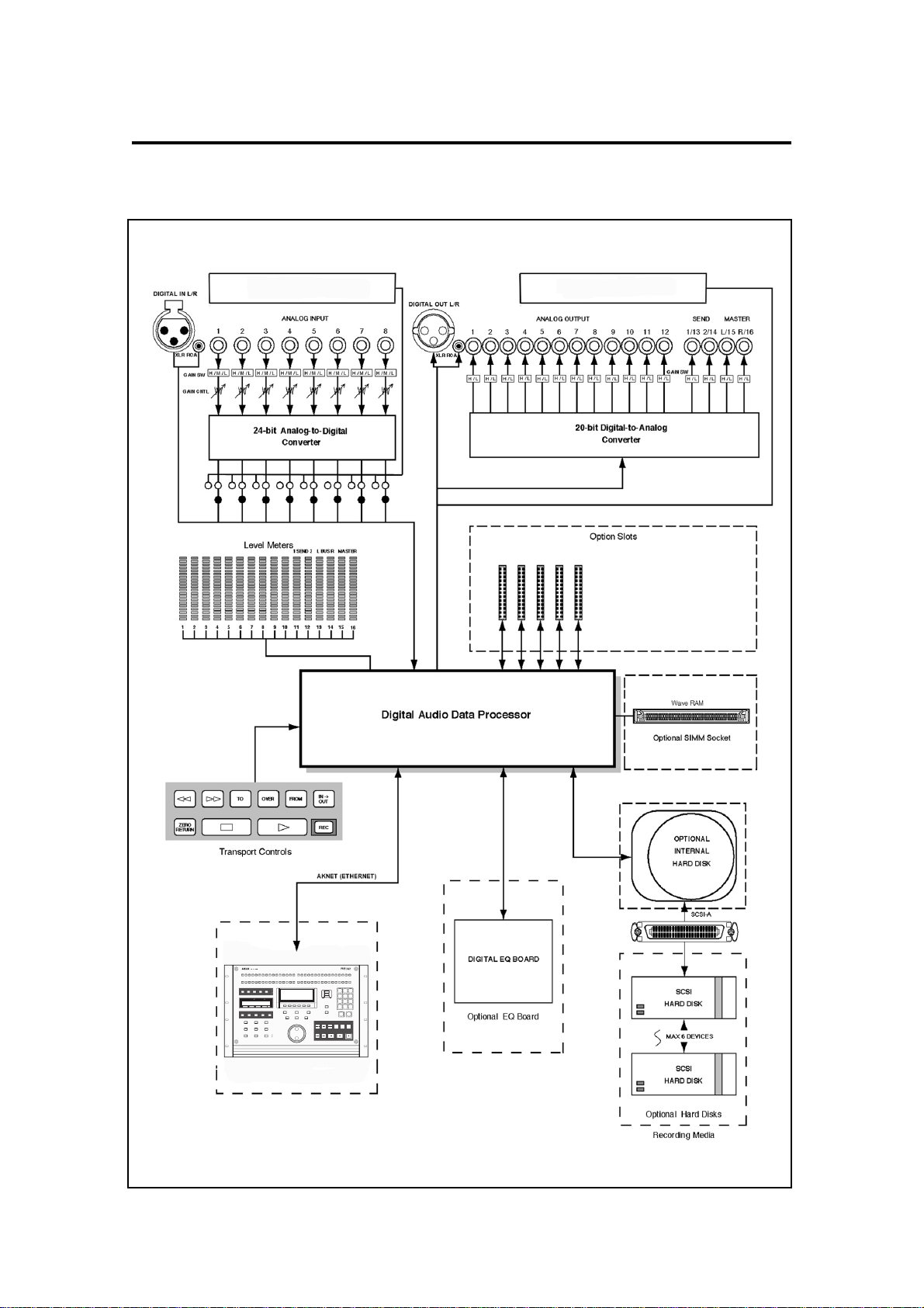
Signal Flow
DAC
DAC
TRACK OUT
1,3,5,7,9,11
TRACK OUT
2,4,6,8,10,12
HIGH (0)
LOW (–10)
HIGH (0)
LOW (–10)
LEVEL SW
CHANNEL OUT
1,3,5,7,9,11
1/4" STEREO JACK
CHANNEL OUT
2,4,6,8,10,12
1/4" STEREO JACK
DAC
DAC
HIGH (0)
LOW (–10)
HIGH (0)
LOW (–10)
LEVEL SW
CHANNEL OUT 13
or SEND 1
1/4" STEREO JACK
CHANNEL OUT 14
or SEND2
1/4" STEREO JACK
DAC
DAC
HIGH (0)
LOW (–10)
HIGH (0)
LOW (–10)
LEVEL SW
CHANNEL OUT 15
or MASTER L
1/4" STEREO JACK
CHANNEL OUT 16
or MASTER R
1/4" STEREO JACK
PHONES
1/4" STEREO JACK
DIGITAL OUT
XLR
RCA
TRACK OUT 13
TRACK OUT 14
TRACK OUT 15
TRACK OUT 16
MX or MULT
PHONES LEVEL
EQ
(OPTION)
TRACK OUT
1–16
CH LEVEL
PAN
SOLO
BUS ON
MONO/STEREO
SENDS LEVEL
SEND PAN
SEND2 LEVEL
SEND1 LEVEL
PRE/POST
HARD DISK
REC
REC or PLAY
AUX IN
TRACK 16
TRACK 2
TRACK 1
INPUT SELECT
OFF
TRACK OUT 1
2
16
POST
PRE
MIXER VALUE
MIXER VALUE
or LEVEL
METER
METER
SEND BUS MASTER
12LRLR
11101 1213141516
MASTER L
MASTER R
SEND I/L
SEND 2/R
BUS L
BUS R
ADC
GAIN VR
(–10 to –22)
LOW (–10)
MID (+20)
HIGH (+40)
INPUT
1, 3, 5, 7
INPUT 1
1/4" STEREO
JACK
ADC
GAIN VR
(–10 to –22)
LOW (–10)
MID (–20)
HIGH (+40)
INPUT
2, 4, 6, 8
INPUTS 1 ... 8
INPUT 2
1/4" STEREO
JACK
INPUT 8 or DIGITAL 8
DIN L
DIN R
BUS L
BUS R
INPUT 1 or DIGITAL 1
INPUT 2 or DIGITAL 2
DIGITAL IN
XLR
DIN R
DIN L
RCA
GAIN SW
DAC
DAC
MAS-
TER
LEVEL
DIGITAL INPUT OPTION
(ADAT or TDIF or AES/EBU)
Introduction
Page 3

Introduction
Description of Signal Flow
Input
A signal input to the ANALOG INPUT channels 1 to 16 passes through the gain switches (HIGH,
MID, LOW) and the GAIN controls. The signal is then converted to digital. Alternatively, pressing
the DIGI key will select DIGIT AL INPUT for channels 1 to 8 from the optional Digital Audio Interface
(eg. ADAT or AES/EBU).
After digital conversion, the signal goes to the INPUT SELECT switches and then to the hard disk
for recording.
At the INPUT SELECT switches, input channels 1 to 8 usually correspond to hard disk tracks 1 to
8 and tracks 9 to 16. However, you can assign any input channel to any hard disk track. You can
also select the BUS L and BUS R signals as inputs or the built-in stereo AES or S/PDIF inputs, DIN
L and DIN R.
Press the appropriate TRACK REC keys to record data to the hard disk tracks. For Analog inputs,
you need to set the recording levels with the GAIN controls. Then press the Play and REC keys to
record.
Output
On playback, the signal from the hard disk tracks passes through the CHANNEL ON keys 1 to 16
and into the TRACK MIX section of the mixer. In addition, the signal is sent to the individual
ANALOG OUTPUT channels 1 to 16. Unlike the inputs, these output channels are fixed to the
corresponding hard disk tracks.
TRACK MIX
In the TRACK MIX section, the signal passes through the equalizer (if the optional digital EQ board
is installed), channel level, pan, and effects send. It is then sent to the MASTER LEVEL where it is
output in digital through the DIGITAL I/O - MASTER OUT or converted to analog and then to the
MASTER L/R or PHONES outputs. The signal is also sent to the SEND and BUS channels. On the
SEND channels, it is converted to analog and sent to the SEND 1/L-2/R outputs. It only appears
on the BUS channels if the BUS ON switch is selected.
Using the BUS channels allows you to carry out a digital bounce-down recording (ping-pong)
inside the DR16pro with very little deterioration in tonal quality.
Page 4
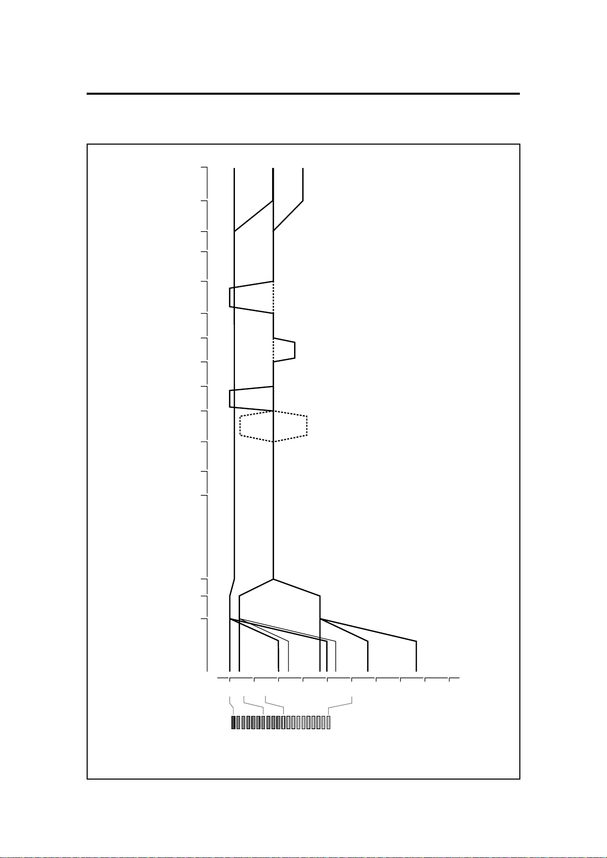
Level Diagram
–dB 50
0
14
6
METER
-10
+200+10
-50
-20
-40
-30
-70
-60
dB
GAIN SW GAIN VR ADC
TRACK
ON/OFFREC/PLAY
EQ
(OPTION) LEVEL PAN
MASTER
LEVEL METERMETERMETER DAC OUT L/R
MASTER L/R
OUTPUT
SW L CLIP
SW L VR MIN
SW M CLIP
SW M VR MIN
SW L VR MAX
SW H CLIP
SW H VR MIN
SW M VR MAX
SW H VR MAX
SOLO
CLIP
VR 9 O'CLOCK
LEVEL-127
LEVEL-104
(DEFAULT)
PAN
L63,R63
PAN-MID
(DEFAULT)
LEVEL-104
(DEFAULT)
SEND 1,2 OUT
INDIVIDUAL
OUTS
H CLIP LEVEL
L CLIP LEVEL
(SAME H/L LEVEL
SEND 1,2
INDIVIDUAL OUTS)
LEVEL-127
Introduction
Page 5
Introduction
Inside the DR16pro
Multi-Channel Digital Input
Optional ADAT or AES/EBU
Multi-Channel Digital Output
Optional ADAT or AES/EBU
IB-802T SMTPE READER/GENERATOR
IB-805R RS422 INTERFACE
IB-803M MIDI INTERFACE
IB-808G GPIO PARALLEL INTERFACE
IB-1616A Alesis™ ADA T INTERFACE
IB-D16MA24 AES/EBU INTERFACE
RE32
MULTITRACK REMOTE CONTROLLER
INPSTOLOC
Page 6
HARD DISK RECORDER
IN OUT EDIT AUTO PUNCH REPEAT
9-16
REHEARSAL
TRACK REC/INPUT SELECT
CHANNEL ON
DIGI
D IN
FINE JOG ON
ESCAPE
STORE/ENT
PREROLL
TIME
:/STACK
SYNC VARI
SPEED
SYNC
SONG BEAT
TIME D TEMPO
RESET ABS/REL LOCATE
JOG SHUTTLE
UNDO
<<MEMO>>
TIME
OVER FROM
TO
TIME
ZERO
RETURN
REC
IN ->
OUT
TO
COPY
MOVE
FROM
METER
POWER
ON
OFF
LEVEL
MIN MAX
PHONES
SNAPSHOT
MAP
SOLO
MIX
MIXER
SUB-MENU
TAKE5
COMMIT
TAKE4TAKE3
DISCARD
TAKE2TAKE1
RESERVED
12345678
GAIN
123
789
LAST
0/-
SET UPDIGIDISK
UTILITY
456
FOOT SW
123456789
MASTERL BUS R1 SEND 2
50 –dB
0614
–dB 50
1/9
0
6
14
ABS
REL
S-M
SONG
EDIT MIX
BUSY
1 2 3 4 5 6 7 8 9
OFFSET
2/10 3/11 4/12 5/13 6/14 7/15
8/16
1/9
2/10 3/11 4/12
10 11 12 13 14 15
16
10 11 12 13 14 15 16
5/13 6/14 7/15
8/16
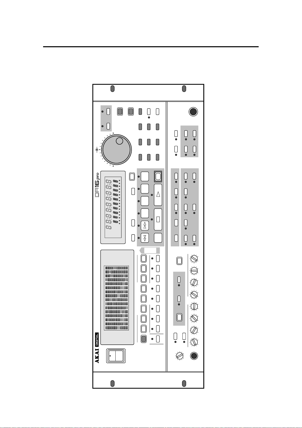
Front and Rear Panels
Front Panel
1: Front and Rear Panels
Page 7
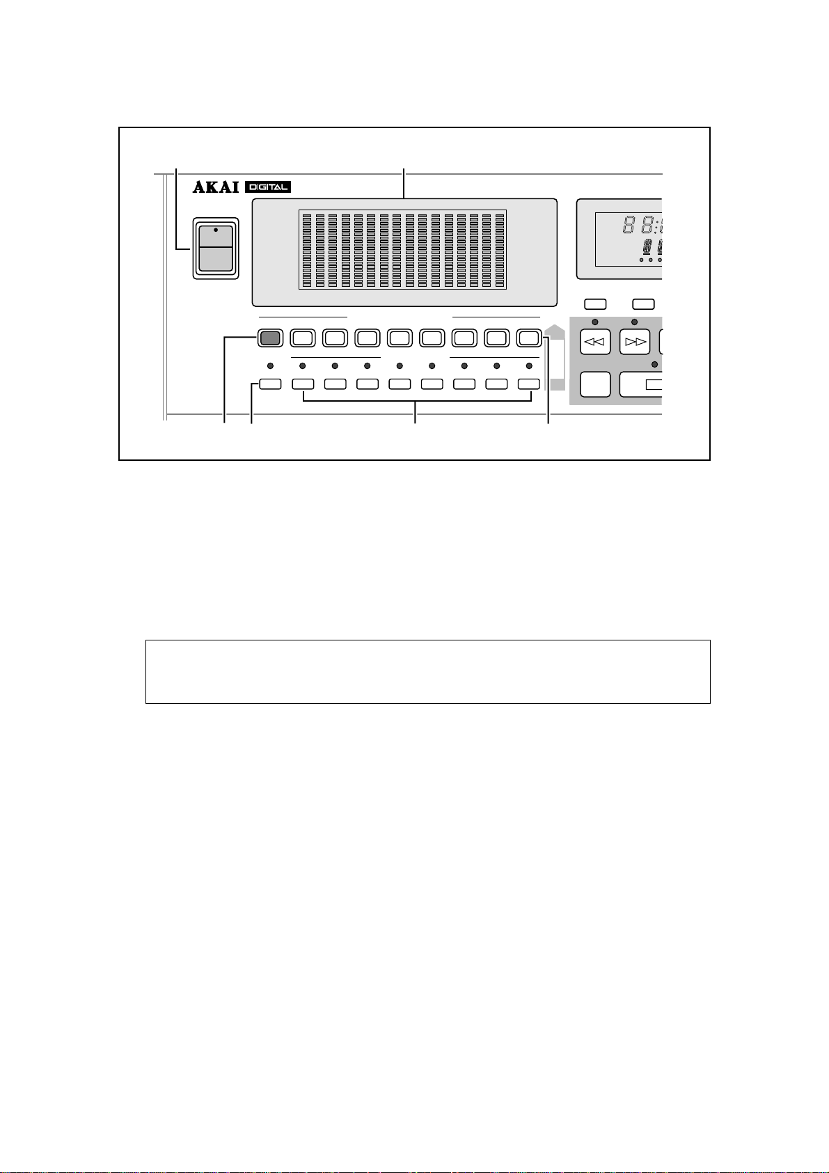
1: Front and Rear Panels
1
2
ABS
REL
S-M
SONG
EDIT MIX
BUSY
HARD D
1 2 3
OFFSET
POWER
ON
OFF
34
METER
0
6
14
–dB 50
123456789
1/9
1/9
DIGI
D IN
MASTERL BUS R1 SEND 2
10 11 12 13 14 15
TRACK REC/INPUT SELECT
2/10 3/11 4/12
2/10 3/11 4/12 5/13 6/14 7/15
5/13 6/14 7/15
CHANNEL ON
5
0
6
14
50 –dB
16
8/16
8/16
6
TO
COPY
MOVE
FROM
RESET ABS/REL
ZERO
RETURN
1) POWER switch
The rocker part of the power switch is recessed in the ON position to prevent accidental
power off.
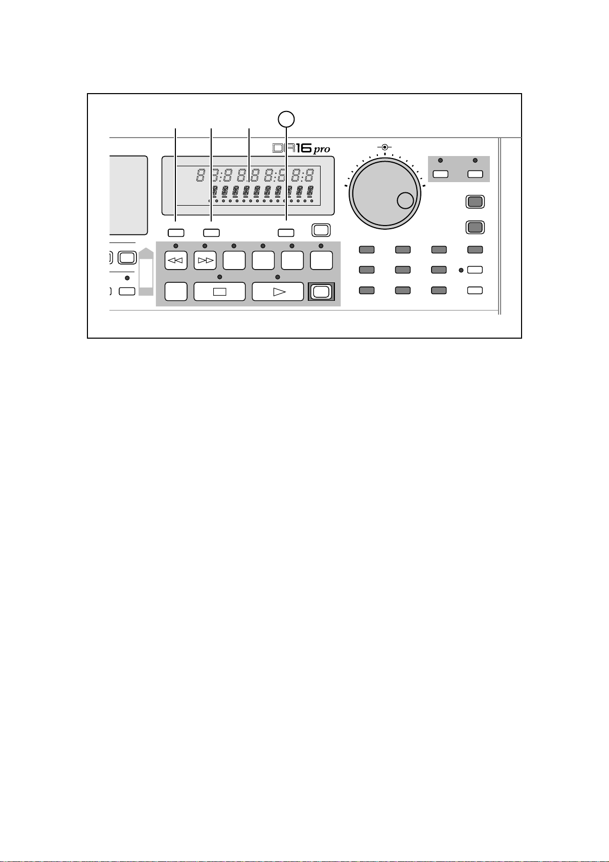
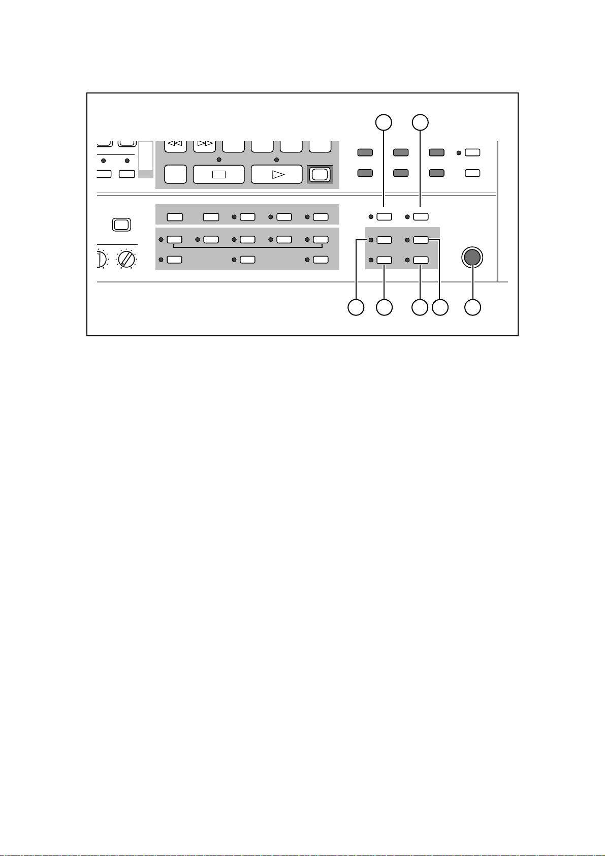
2) Peak Level meters
These 20-segment FLD (Fluorescent Light Display) bargraphs with peak hold indicate the
playback and source levels. There are sixteen track level indicators that also indicate the
send, bus routing, and stereo master levels. The bargraphs are used to display channel pa-
rameter settings when the DR16pro is in Mix Mode.
Note: These meters are after the A/D converters in the signal path. Therefore when the
amber 0 dB (Peak) FLD segment lights, it indicates digital distortion. You should adjust
the levels so this never occurs.
3) METER key
This key toggles the level meter indicator between channel and master. Normally, the level
meter shows the level of each track. Pressing the METER key changes tracks 11-16 indica-
tors to send, bus, and master level indicators.
4) DIGI(D IN) key
This key selects digital inputs for input channels 1 – 8 from the optional ADAT or AES/EBU
digital audio interface. (Select the XLR or the RCA/phono connectors with the DIGI(D IN) sub-
menu function.) See “Digital Inputs” on page 33.
This key is also used for selecting either the XLR or RCA connector (DIN-L / DIN-R).
5) CHANNEL ON keys 1/9 ~ 8/16
These keys allow you to select channels for monitoring. See “Track Number Limitations” on
page 42. When you are using the Mix Mode, these keys select the channel you want to edit.
Also see “Selecting Mix Mode” on page 61.
6) TRACK REC(INPUT SELECT) keys 1/9 ~ 8/16
These keys are used to arm tracks for recording (“Arming Tracks” on page 38) or to select
auxiliary inputs (“Setting an Auxiliary Input” on page 64.) A flashing key indicates that a track
is armed for recording, and a lit key indicates recording in progress. Assign the input channel
for each track using the TRACK REC (INPUT SELECT) sub-menu function (“Selecting the
Input Channels” on page 35).
Page 8
1: Front and Rear Panels
10
10 11 12 13 14 15 16
OVER FROM
TIME
UNDO
IN ->
OUT
<<MEMO>>
REC
JOG SHUTTLE
FINE JOG ON
789
456
UTILITY
123
SET UPDIGIDISK
ESCAPE
STORE/ENT
LAST
0/-
PREROLL
TIME
:/STACK
0
6
14
50 –dB
8/16
8/16
789
HARD DISK RECORDER
ABS
REL
S-M
SONG
EDIT MIX
BUSY
1 2 3 4 5 6 7 8 9
RESET ABS/REL LOCATE
OFFSET
COPY
MOVE
FROM
TO
ZERO
RETURN
TO
TIME
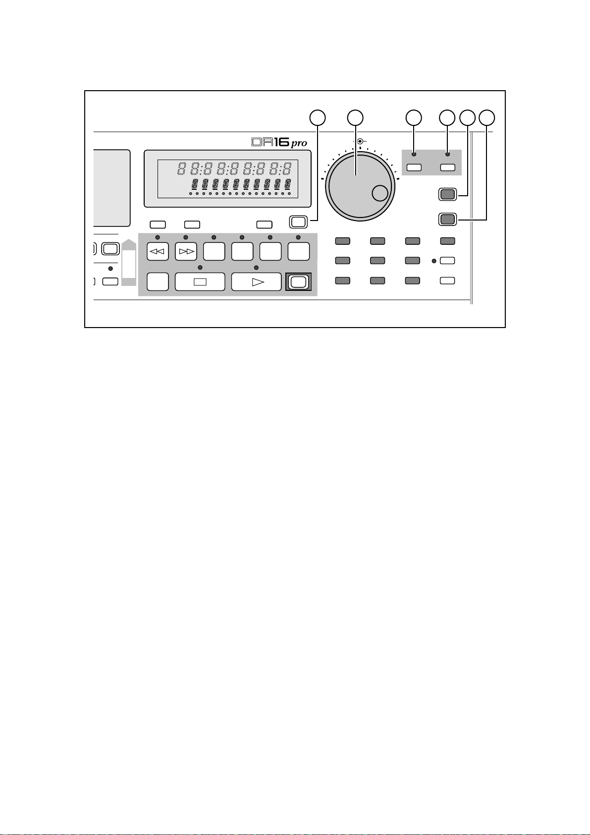
7) RESET key
This key is used to reset the relative time to zero. If it is pressed while an absolute time is
displayed, relative time will be selected automatically, just like pressing the ABS/REL key.
8) ABS/REL(OFFSET) key
This key switches the display between absolute time and relative time. Absolute time starts at
zero, cannot be changed, and works as the base time for relative time. When synchronizing
using SMPTE timecode, the relative mode can be used to set synchronization offsets.
Set the offset for relative time with the ABS/REL(OFFSET) sub-menu function.
9) Time and Status display
This custom FLD (Fluorescent Light Display) shows recording time information and mes-
sages indicating the system status.
The top row of nine 7-segment digits display time, either absolute or relative. It may also be
switched to show bars, beats, and clocks.
The bottom row of 14-segment digits display status, sub-menu, and error messages. Also in
this display, the current mode is displayed.
The “BUSY” indicator at the bottom of the display shows hard disk activity . Beside it, a row of
small dots show activity for each of the 16 tracks and indicate that data exists on the track at
the current position.
10) LOCATE key
This key is used to enter locate time values. See “Locate Functions” on page 77 and “Speci-
fying the “in” Point and “out” Point” on page 26.
Page 9
1: Front and Rear Panels
11 12 13 14 15 16
JOG SHUTTLE
FINE JOG ON
789
456
UTILITY
123
SET UPDIGIDISK
ESCAPE
STORE/ENT
LAST
0/-
PREROLL
TIME
:/STACK
0
6
14
50 –dB
8/16
8/16
HARD DISK RECORDER
ABS
REL
S-M
SONG
EDIT MIX
BUSY
1 2 3 4 5 6 7 8 9
RESET ABS/REL LOCATE
OFFSET
TO
COPY
MOVE
FROM
ZERO
RETURN
TO
TIME
10 11 12 13 14 15 16
OVER FROM
TIME
UNDO
IN ->
OUT
<<MEMO>>
REC
11) UNDO key
This key allows you to undo the last recording or edit. This is useful if you make a mistake
while recording and want to return to the previous recording. Likewise, when editing you can
compare the material before and after an edit. See “Recording Undo” on page 44 and “Undo-
ing an Edit” on page 85.
12) JOG/SHUTTLE control
The inner JOG wheel allows you to locate while listening to a recording. Playback speed is
determined by how fast you turn the wheel. Turn it counterclockwise to review and clockwise
to preview. The ef fect is similar to reel-rocking on an analog tape recorder — you can use it to
identify edit points precisely. In certain modes such as MIX, SONG and SUB-MENU, this
wheel is also used for data entry. Turn it counterclockwise to decrease values and clockwise
to increase them.
Like the JOG wheel, the outer SHUTTLE control also allows you to locate while listening to a
recording. The playback speed is determined by the angle at which you hold the control. Turn
it counterclockwise to review and clockwise to preview. The SHUTTLE control is also used to
move the cursor (input point) when setting certain parameter values. See “Cursor” on page
25.
13) FINE key
This key allows you to increase the resolution of the jog wheel for more precise selection of
time location points.
14) JOG ON key
This key allows you to switch the JOG/SHUTTLE control on and off. When the LED is lit, the
JOG/SHUTTLE control can be used to locate while listening to a recording. Otherwise, the
JOG/SHUTTLE control cannot be used to locate.
15) ESCAPE key
This key can be used to escape from the current edit or sub-menu function.
16) STORE/ENT key
This key is used when entering and storing time values, executing edit functions, etc.
Page 10
1: Front and Rear Panels
JOG SHUTTLE
FINE JOG ON
789
456
UTILITY
123
SET UPDIGIDISK
ESCAPE
STORE/ENT
LAST
0/-
PREROLL
TIME
:/STACK
0
6
14
50 –dB
8/16
8/16
HARD DISK RECORDER
ABS
REL
S-M
SONG
EDIT MIX
BUSY
1 2 3 4 5 6 7 8 9
RESET ABS/REL LOCATE
OFFSET
COPY
MOVE
FROM
TO
ZERO
RETURN
TO
TIME
10 11 12 13 14 15 16
OVER FROM
TIME
UNDO
IN ->
OUT
<<MEMO>>
REC
17 18 19 20
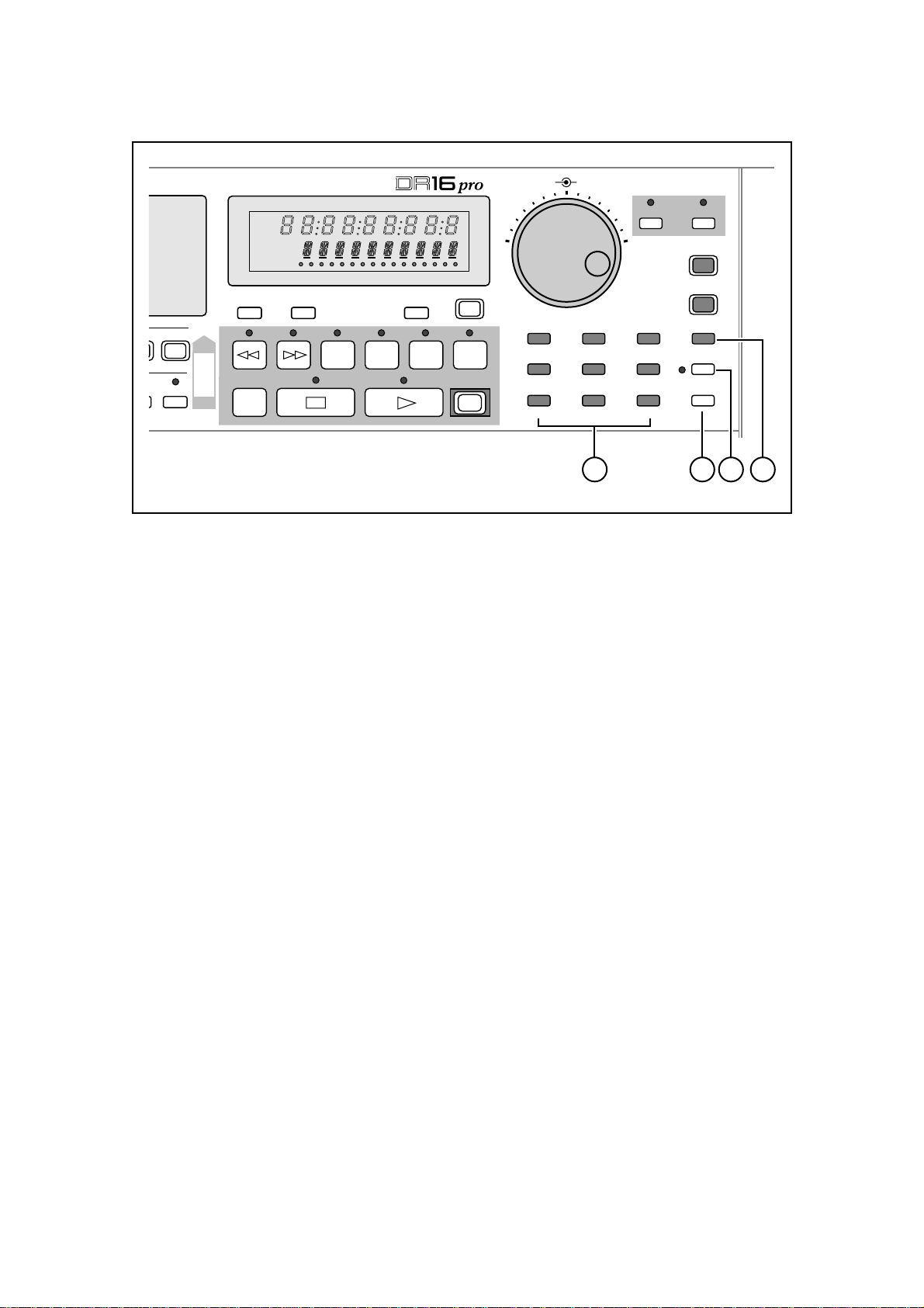
17) Numeric keypad - 1(DISK), 2(DIGI), 3(SET UP), 4(UTILITY), 5, 6, 7, 8, 9
These keys are used to store and recall direct locate points, enter time values, and set param-
eter values.
You can perform a variety of operations on the hard disk with the 1(DISK) sub-menu func-
tions.
Set the sampling frequency and other related functions with the 2(DIGI) sub-menu functions.
Adjust the display brightness, drop the sub-frame notation, and assign MIDI controller num-
bers with the 3(SET UP) sub-menu functions. See “System Set up” on page 134.
The 4(UTILITY) sub-menu functions are used for loading, saving or creating projects.
18) :/ST ACK key
This key is used to enter and recall the 100 stack locate points (00-99). It is also used as a
shortcut during locate data entry. See “Stack Locate Points” on page 79.
19) PREROLL(TIME) key
This key is used to switch on the preroll function. Preroll allows you to locate to a point a few
seconds before a specified point, for example, to provide a count-in to an overdub. See “Preroll”
on page 81.
The preroll value is set using the PREROLL(TIME) sub menu function.
20) LAST 0/– key
This key is used to locate to the last two points at which the stop key was pressed. Press the
key once to locate to the last point at which the stop key was pressed. Press again to locate to
the previous point. See “Last Memory” on page 80.
This key is also used for entering time and parameter values, and entering negative values.
Page 11
1: Front and Rear Panels
JOG SHUTTLE
FINE JOG ON
789
456
UTILITY
123
SET UPDIGIDISK
ESCAPE
STORE/ENT
LAST
0/-
PREROLL
TIME
:/STACK
0
6
14
50 –dB
8/16
8/16
HARD DISK RECORDER
ABS
REL
S-M
SONG
EDIT MIX
BUSY
1 2 3 4 5 6 7 8 9
RESET ABS/REL LOCATE
OFFSET
COPY
MOVE
FROM
TO
ZERO
RETURN
TO
TIME
10 11 12 13 14 15 16
OVER FROM
TIME
UNDO
IN ->
OUT
<<MEMO>>
REC
21 22 23 24 25 26
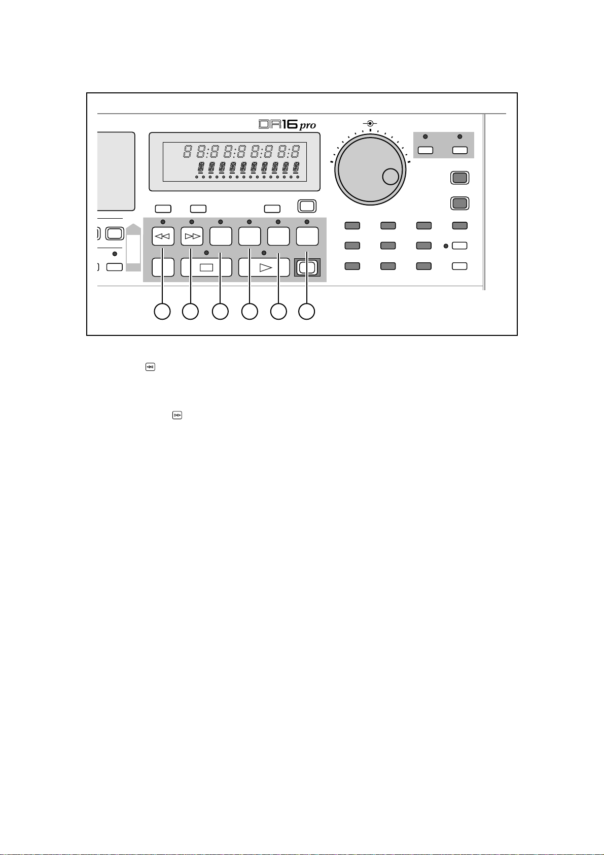
21) Rewind key
This key is like the rewind key found on most conventional tape recorders. In stop mode, it
activates time display fast rewind.
22) Fast Forward key
This key is like the fast forward key found on most conventional tape recorders. In stop mode,
it activates time display fast forward.
23) TO(TIME) key
This key will start playback at a specified number of seconds before the current position, i.e.,
the currently displayed time. The default is one second. Playback will stop when the current
position is reached. The number of seconds can be specified in the TO(TIME) sub-menu
function.
24) OVER key
This key will start playback at a specified number of seconds before the current position.
Playback will stop the same number of seconds beyond the current point. The default is one
second before and one second after the current point. The number of seconds are specified
with the TO(TIME) and FROM(TIME) sub-menu functions.
25) FROM(TIME) key
This key will start playback at the current position. Playback will stop a specified number of
seconds beyond the current point. The default is one second. The number of seconds can be
specified in the FROM(TIME) sub-menu function.
26) IN->OUT(<<MEMO>>) key
This key will start playback from the current “in” point to the current “out” point. You set these
points with “IN key”“OUT key” on page 16. After playback, the DR16pro returns to the original
time. You can save up to nine specific “in” and “out” points with the IN->OUT(<<MEMO>>)
sub-menu function. See “Using the <<MEMO>> function” on page 27.
Page 12
1: Front and Rear Panels
JOG SHUTTLE
FINE JOG ON
789
456
UTILITY
123
SET UPDIGIDISK
ESCAPE
STORE/ENT
LAST
0/-
PREROLL
TIME
:/STACK
0
6
14
50 –dB
8/16
8/16
HARD DISK RECORDER
ABS
REL
S-M
SONG
EDIT MIX
BUSY
1 2 3 4 5 6 7 8 9
RESET ABS/REL LOCATE
OFFSET
COPY
MOVE
FROM
TO
ZERO
RETURN
TO
TIME
10 11 12 13 14 15 16
OVER FROM
TIME
UNDO
IN ->
OUT
<<MEMO>>
REC
27 28 29 30
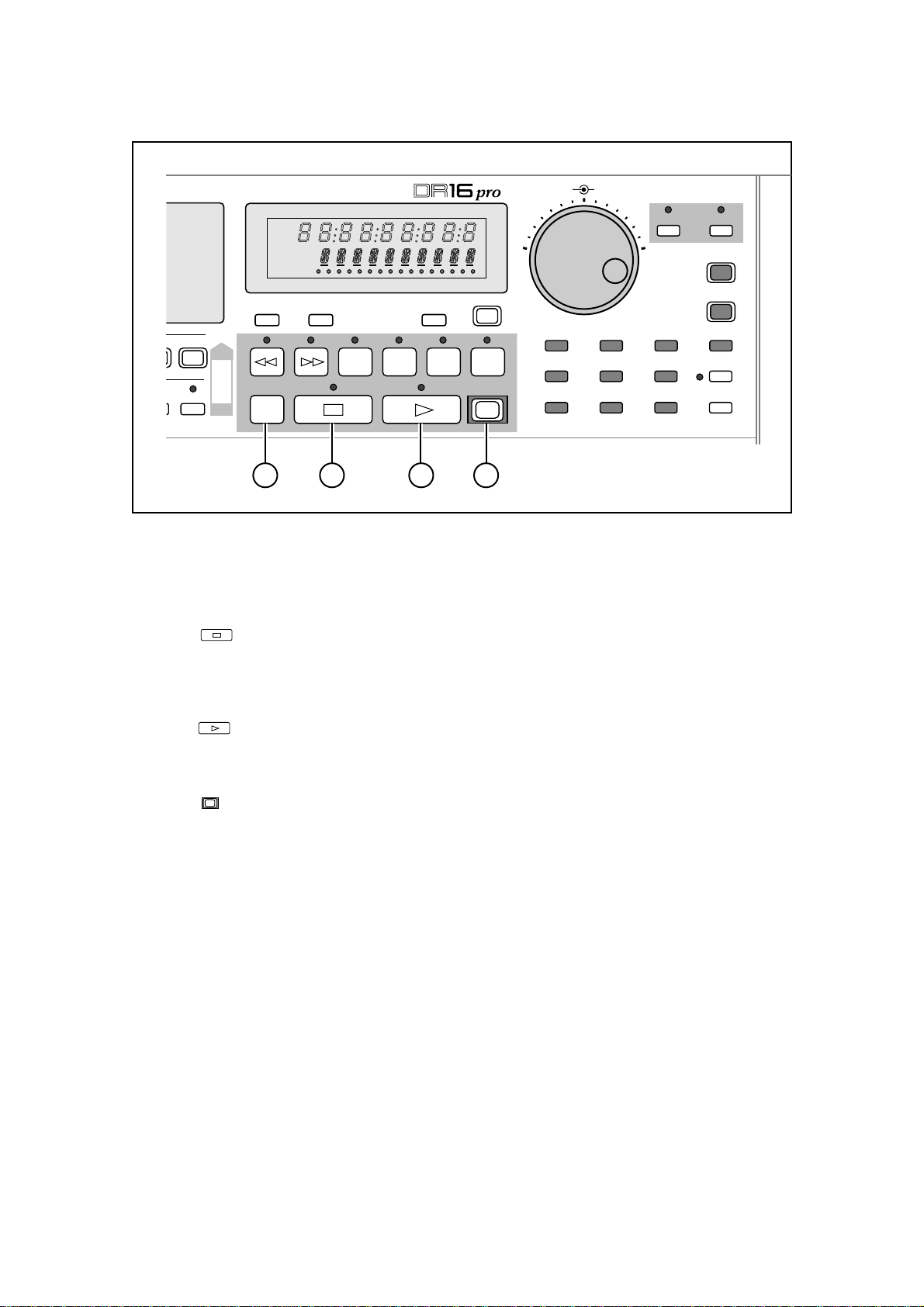
27) ZERO RETURN key
In absolute mode, this key will locate to the absolute 00:00:00:00:0 point.
In relative mode, it will locate to the relative 00:00:00:00:0 point.
28) Stop key
This key is used to stop playback, recording, fast forward, and rewind.
When Stop is pressed, the last two stop points are stored in memory . You can use the LAST
0/- key to switch between the last two stop points.
29) Play key
This key is used to start playback. Pressing this key while holding down the REC key will start
recording.
30) REC key
This key (in combination with the Play key) is used to start recording. It flashes when the
DR16pro is in record-ready mode (TRACK REC keys have been selected) and lights up while
recording is in progress.
Page 13
1: Front and Rear Panels
31 33 34 35 36 37
8/16
COPY
MOVE
FROM
ZERO
RETURN
IN OUT
RESERVED
TAKE2TAKE1
LEVEL
MIN MAX
PHONES
CHANNEL ON
DIGI
1/9
2/10 3/11 4/12 5/13 6/14 7/15
D IN
9-16
REHEARSAL
12345678
MIX
MIXER
SOLO
GAIN
SNAPSHOT
MAP
SUB-MENU
32
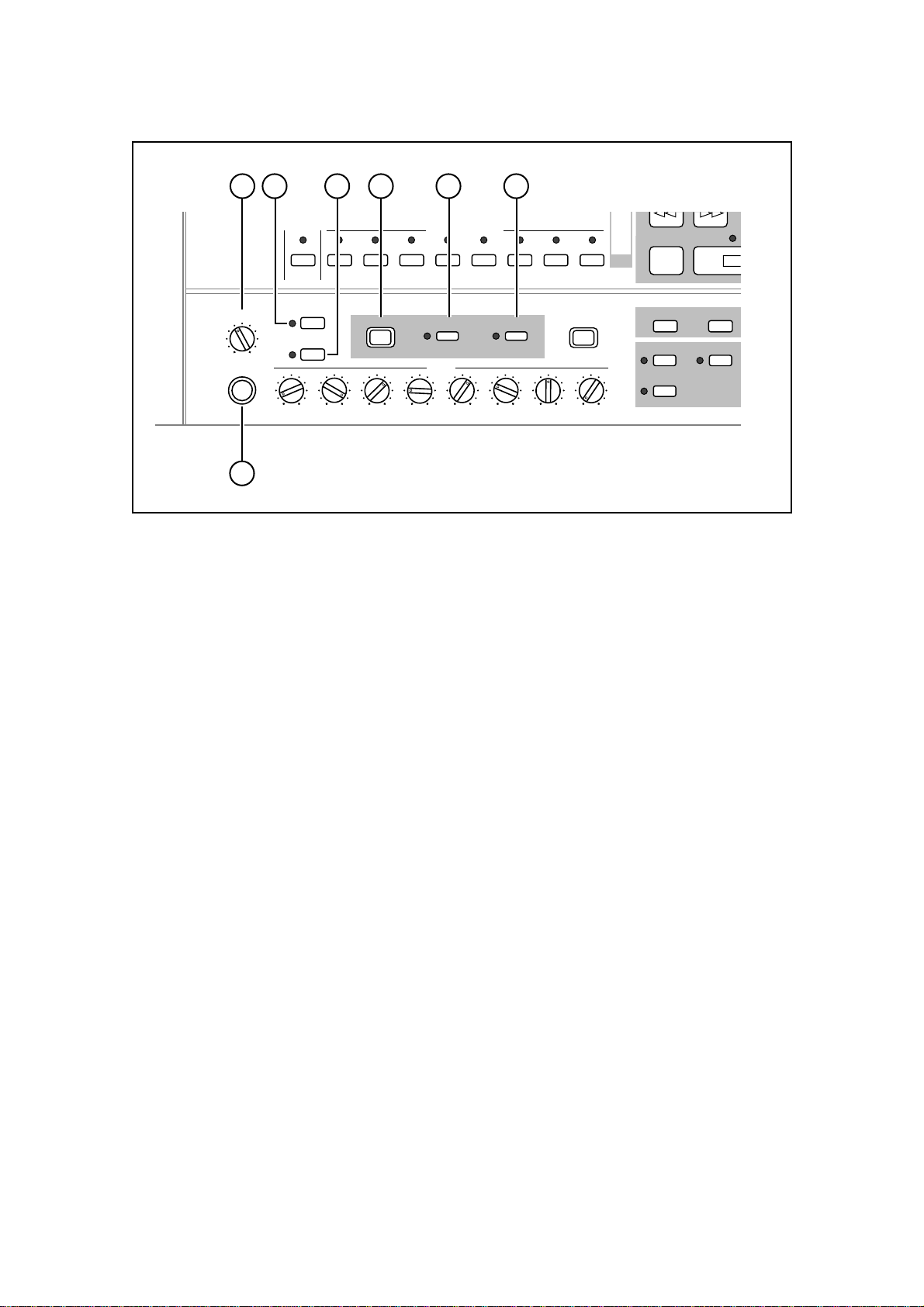
31) Phones LEVEL
This control adjusts the headphone volume level.
32) PHONES connection
A stereo pair of headphones can be connected to this 1/4 inch stereo phone jack.
33) 9 ~ 16 key
This key toggles the TRACK REC keys and the CHANNEL ON keys between selecting tracks
or channels 1~8 and 9~16.
34) REHEARSAL key
This key turns the rehearsal function on and off. Rehearsal allows you to practice punch-ins
and -outs. During a rehearsal, the monitor will switch to source at the punch-in point, but
nothing will be recorded. See “Rehearsal” on page 43.
35) MIX(MIXER) key
This key allows you to configure the mixer — set the level, pan and auxiliary send levels for
each channel. See “Mixer” on page 60.
Set global mixer parameters such as the master level, auxiliary send types, and metering
parameters with the MIX(MIXER) sub-menu function. See “System Settings” on page 65.
36) SOLO key
This key allows you to isolate individual channels. Pressing one of the CHANNEL ON keys
will switch off all other tracks, so that you may listen to the selected track in isolation. You can
select more than one track at a time. See “Solo Function” on page 71.
37) SNAPSHOT(MAP) key
This key allows you to store a mix as a ‘snapshot’. Once stored, this key is used to recall
snapshot mixes. See “Snapshot Settings” on page 68.
Page 14
1: Front and Rear Panels
38
8/16
COPY
MOVE
FROM
ZERO
RETURN
IN OUT
RESERVED
TAKE2TAKE1
LEVEL
MIN MAX
PHONES
CHANNEL ON
DIGI
1/9
2/10 3/11 4/12 5/13 6/14 7/15
D IN
9-16
REHEARSAL
12345678
MIX
MIXER
SOLO
GAIN
SNAPSHOT
MAP
SUB-MENU
39
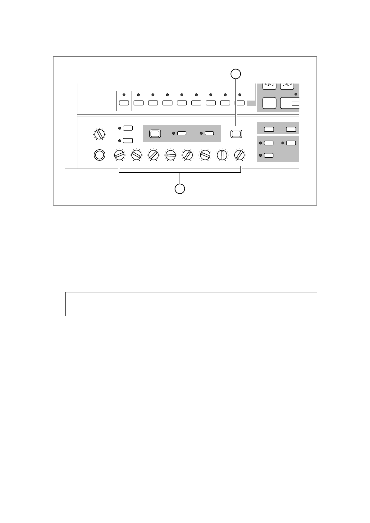
38) SUB-MENU key
This key is used to select sub-menu functions. Many of the keys have sub-menu functions
(indicated in amber, usually beneath the key).
To select a sub-menu function, press the SUB-MENU key (the indicator in the key will flash
and the text “SUB-MENU” will appear on the display), then press the desired key. While the
DR16pro is in Sub-Menu mode, the amber “S-M” indicator will be lit on the display.
39) GAIN controls
These controls allow you to set the level of the eight analog inputs on the rear panel.
Note: The settings of these controls are not stored as part of a mixer snapshot. See
“Storing a Snapshot” on page 68.
Page 15
1: Front and Rear Panels
40 41 42 43 44
TO
COPY
MOVE
8/16
7/15
FROM
ZERO
RETURN
TO
TIME
OVER FROM
TIME
IN ->
OUT
<<MEMO>>
REC
456
UTILITY
123
SET UPDIGIDISK
PREROLL
TIME
:/STACK
SUB-MENU
78
IN OUT EDIT AUTO PUNCH REPEAT
TAKE4TAKE3
RESERVED
TAKE2TAKE1
DISCARD
TAKE5
COMMIT
SYNC VARI
SYNC
SONG BEAT
TIME D TEMPO
SPEED
FOOT SW
45 46 47 48
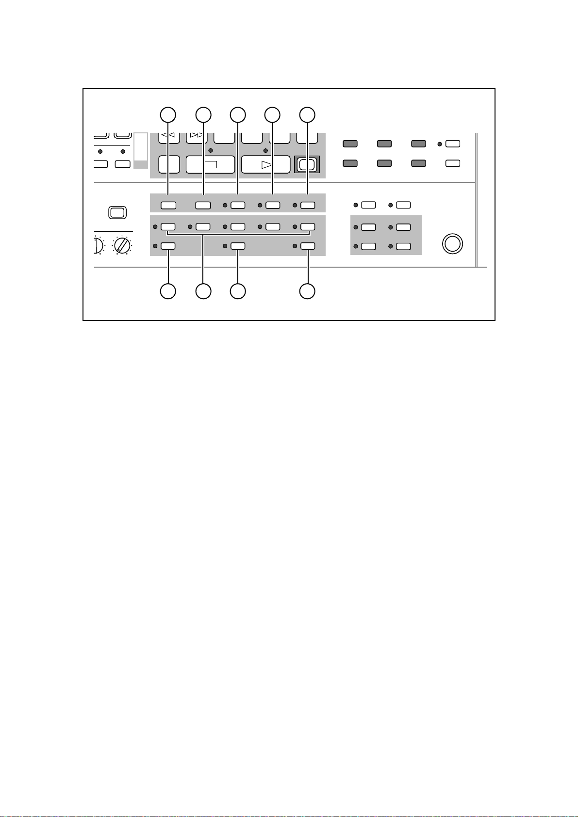
40) IN key
This key sets the DR16pro to the “in” point. To store an “in” point, first press the STORE/ENT
key (this marks the time) and then press the IN key.
41) OUT key
This key sets the DR16pro to the “out” point. To store an “out” point, first press the STORE/
ENT key and then press the OUT key.
42) EDIT key
This key is used to select the edit functions. See “Editing” on page 84.
43) AUTO PUNCH key
This key is used to automatically control recording punch-in and punch-out. See “Auto Punch-
In/Out” on page 41.
44) REPEAT key
This key is used to repeat playback. When this key is on, the part between the “in” point and
the “out” point will be played back repeatedly. See “Repeat” on page 52.
45) RESERVED key
This key assigns a recording or edit to one of the TAKE keys.
46) TAKE1 to TAKE5 keys
These keys are used to keep the last 5 recordings. See “Take Functions” on page 73.
47) DISCARD key
This key allows you to delete the contents of one of the TAKE keys.
48) COMMIT key
This key saves the “perfect” take to the hard disk tracks.
Page 16
1: Front and Rear Panels
TO
COPY
MOVE
8/16
7/15
SUB-MENU
78
FROM
OVER FROM
TO
TIME
ZERO
RETURN
IN OUT EDIT AUTO PUNCH REPEAT
TAKE2TAKE1
RESERVED
DISCARD
TIME
TAKE4TAKE3
IN ->
OUT
<<MEMO>>
REC
TAKE5
COMMIT
49
456
UTILITY
123
SYNC VARI
SYNC
SONG BEAT
TIME D TEMPO
50
SPEED
PREROLL
TIME
:/STACK
SET UPDIGIDISK
FOOT SW
51 52 53 5554
49) SYNC(SYNC) key
This key is used to activate synchronization with an external device. The optional IB-802T
SMPTE reader/generator board is required for SMPTE synchronized operation; the optional
IB-803M MIDI interface board is required for MIDI operation; the optional IB-805R RS422
interface board is required for RS422 operation.
Select the type of external device to sync to with the SYNC(SYNC) sub-menu function. See
“SMPTE/EBU Synchronization” on page 118 and “MIDI Synchronization” on page 121.
50) VARI(SPEED) key
This key switches on the varispeed function for playback. See “Varispeed” on page 53.
The amount of varispeed is set using the VARI(SPEED) sub-menu function.
51) SONG key
This key switches the display to BBC mode: Bar, Beat, Clock. This mode is mainly used when
the DR16pro is synchronized to a MIDI Clock (MTC) signal with the optional IB-803M MIDI
interface board. See “Song Mode” on page 127.
52) TIME D key
This key is used to switch to normal time display (hours, minutes, seconds, frames) when the
DR16pro is in BBC mode.
53) TEMPO key
This key is used to set the tempo when the DR16pro is in BBC mode.
You may also use this key to input tempo changes. When an external sequencer is slaved to
the DR16pro, it will be able to follow tempo changes.
54) BEAT key
This key is used to set the time signature when the DR16pro is in BBC mode.
55) FOOT SW connection
A normally closed type footswitch can be connected here for punch-in and punch-out opera-
tion.
Page 17
1: Front and Rear Panels
LR
LOW HIGH
MASTER
12
HIGH LOW
GAIN MID
78
HIGH LOW
GAIN MID
34
HIGH LOW
GAIN MID
56
HIGH LOW
GAIN MID
LR
LOW HIGH
MASTER
SEND
12
LOW HIGH
OFF
ON
SCSI-B ID
NC T 4 2 1
O/OFF
I/ON
MASTER
SLAVE
SCSI-A
SIGNAL
GND
LR
LOW HIGH
MASTER
DIGITAL I/O L/R
MODEL NUMBER DR16
pro
AKAI ELECTRIC CO., LTD.
MADE IN JAPAN
LR
LOW HIGH
LR
LOW HIGH
LR
LOW HIGH
LR
LOW HIGH
MASTER
ANALOG INPUT
MASTER OUT
IN
PUSH
AKAI NET
SYNC
IN/OUT
TERM
EXPANSION
OFF
ON
TERM
12
LOW HIGH
78
LOW HIGH
34
LOW HIGH
56
LOW HIGH
ANALOG OUTPUT
910
LOW HIGH
11 12
LOW HIGH
AKAI ELECTRIC CO., LTD.AKAI ELECTRIC CO., LTD. MADE IN JAPAN
SERIAL NUMBER
79504-00005
13 14
15 16
Rear Panel
Page 18
1: Front and Rear Panels
1 2 3 4
SCSI-A
DIGITAL I/O L/R
IN
PUSH
MASTER OUT
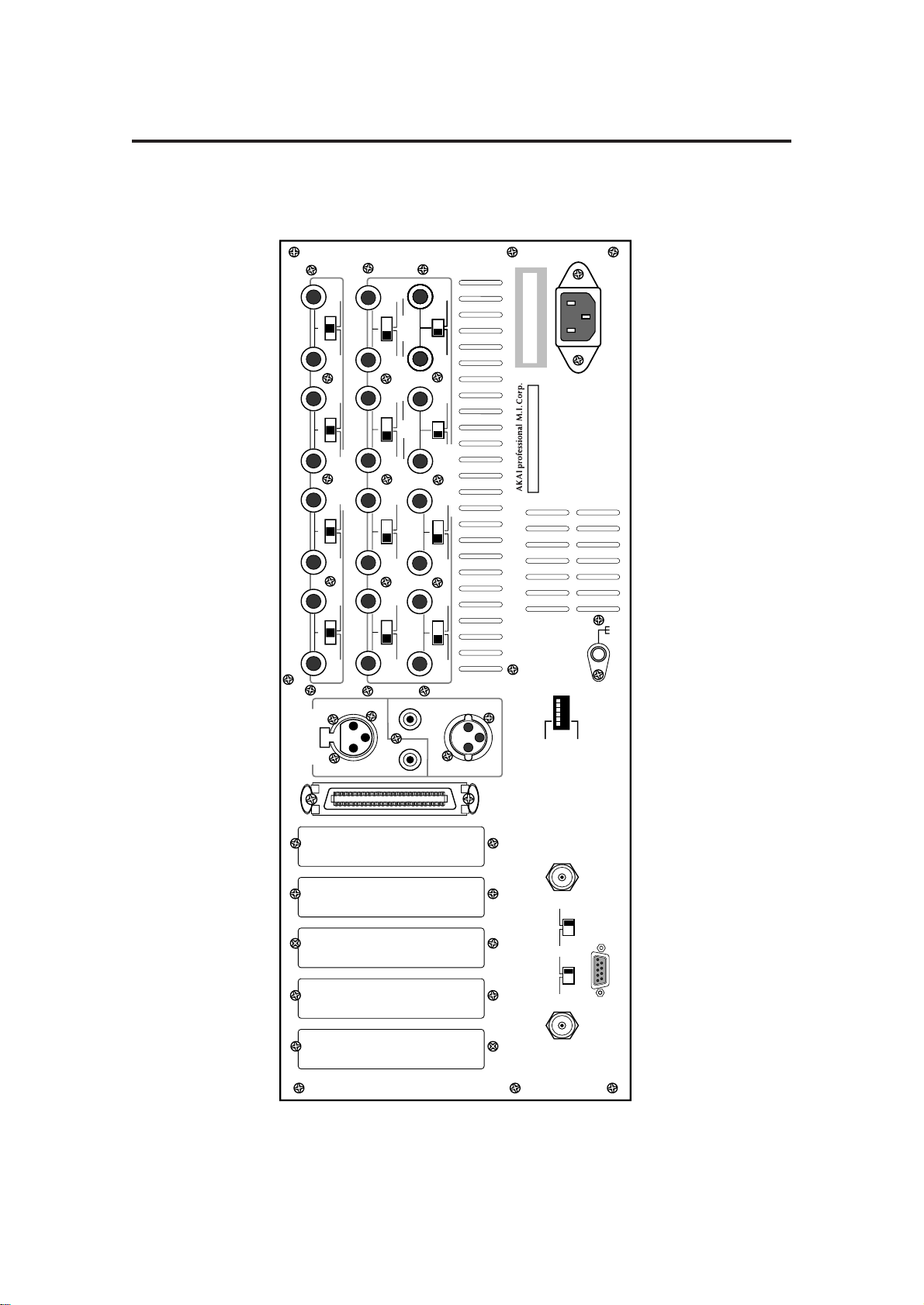
1) Option slots
These slots are for installing the following optional interface cards:
• IB-802T SMPTE reader/generator board
• IB-803M MIDI (IN/OUT/THRU) interface board
• IB-805R RS422 interface board
• IB-808G GPIO parallel interface board
• IB-1616A Alesis ADAT interface board / IB-D16MA 8-in/16-out AES/EBU interface board
2) SCSI-A connection
For increased recording time, up to six external SCSI hard disks can be connected to this
connection (up to seven if the DR16pro contains no internal hard disk). See “Hard Disks” on
page 96.
3) DIGITAL I/O - IN connectors
These XLR and RCA/phono connectors are used to input AES/EBU and S/PDIF format digital
signals respectively. The active input connector is selected using the DIGI(D IN) key sub-
menu function. See “Digital Inputs” on page 33.
The stereo digital input signals from these connectors, DINL and DINR, can be selected from
SUB-MENU/INPUT SELECT as record sources for any track.
4) DIGITAL I/O - MASTER OUT connectors
These XLR and RCA/phono connectors are used to output AES/EBU and S/PDIF format
digital signals. The format of the digital output signal is set to Type I or Type II digital audio
outputs using the 2(DIGI) sub-menu function. See “Digital Outputs” on page 47.
The digital outputs are a digital duplication of the analog signal appearing at the OUTPUT -
MASTER OUT jacks. These may be connected to any stereo digital audio recorder , such as a
DAT machine, to perform a completely digital mixdown.
Page 19
1: Front and Rear Panels
MASTER OUT
AKAI NET
TERM
OFF
ON
EXPANSION
TERM
ON
OFF
SYNC
IN/OUT
MASTER
SLAVE
SCSI-B ID
NC T 4 2 1
O/OFF
I/ON
5 76 8 9
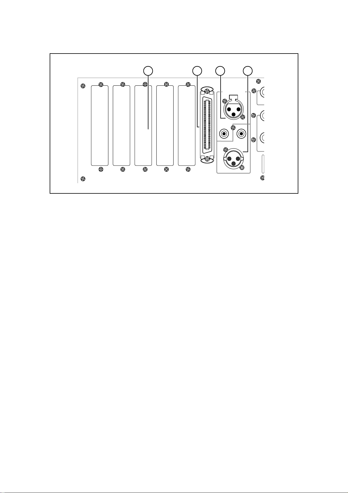
5) AKAINET connection and TERMINATOR switch
This BNC connector is used to connect the DR16pro to other DR16pros or to remote control-
lers such as the RE32. Multiple units can be connected together by chaining the AKAINET
BNC connectors using standard Ethernet BNC cables and ‘T’ pieces. It is essential that the
first and last units in the chain are terminated either by switching the TERM switch to the ON
position or by using an external 50 ohm terminator.
Note:
The AKAINET interface used in the DR16pro is 10-Base-2 Ethernet. There are
certain rules that must be adhered to when setting up the system to ensure reliable
operation:
• All cables must be 50 ohm impedance
• There should be a maximum of 185m of cable in the system between the first and last
nodes.
• There should be at least 0.5m of cable between each node
6) EXPANSION socket
For connection to the Akai MT8 Mix Tab or RC15 remote control.
7) TERM switch
This switch selects 75Ω termination for the SYNC connection. When a video signal is connected, this switch must be set to ON.
8) SYNC connection
This BNC connector is used to connect the DR16pro to an external digital clock source, a
composite color video signal, or a black burst signal. Use the 2(DIGI) sub-menu function to
select wordclock or a variety of video sync options.
9) SCSI-B ID switches
This has no function with this version of software.
Page 20
10 11
1: Front and Rear Panels
GAIN MID
12
HIGH LOW
12
LOW HIGH
910
LOW HIGH
34
HIGH LOW
34
LOW HIGH
11 12
LOW HIGH
GAIN MID
56
ANALOG INPUT
ANALOG OUTPUT
HIGH LOW
56
LOW HIGH
12
13 14
LOW HIGH
GAIN MID
SEND
GAIN MID
78
HIGH LOW
78
LOW HIGH
LR
LR
LR
LR
LR
LR
LR
MASTER
MASTER
MASTER
MASTER
15 16
LOW HIGH
LOW HIGH
LOW HIGH
LOW HIGH
LOW HIGH
LOW HIGH
LOW HIGH
12 13 13 14 15 13
10) ANALOG INPUT (1 ~ 8) connectors
These 1/4 inch stereo phone jacks are used to input analog signals to the DR16pro. They
accept balanced and unbalanced signals: Tip = hot, ring = cold, sleeve = ground. Unlike
conventional multi-track recorders, the eight inputs are not ‘hardwired’ to their corresponding
tracks but can be assigned to any track you like.
11) Input gain switches
These switches allow you to set the DR16pro input gain. They can be set to LOW (0 dB), MID
(+20 dB), or HIGH (+40 dB). Input gain switches are provided for each pair of channels:
channels 1/2, channels 3/4, channels 5/6, and channels 7/8.
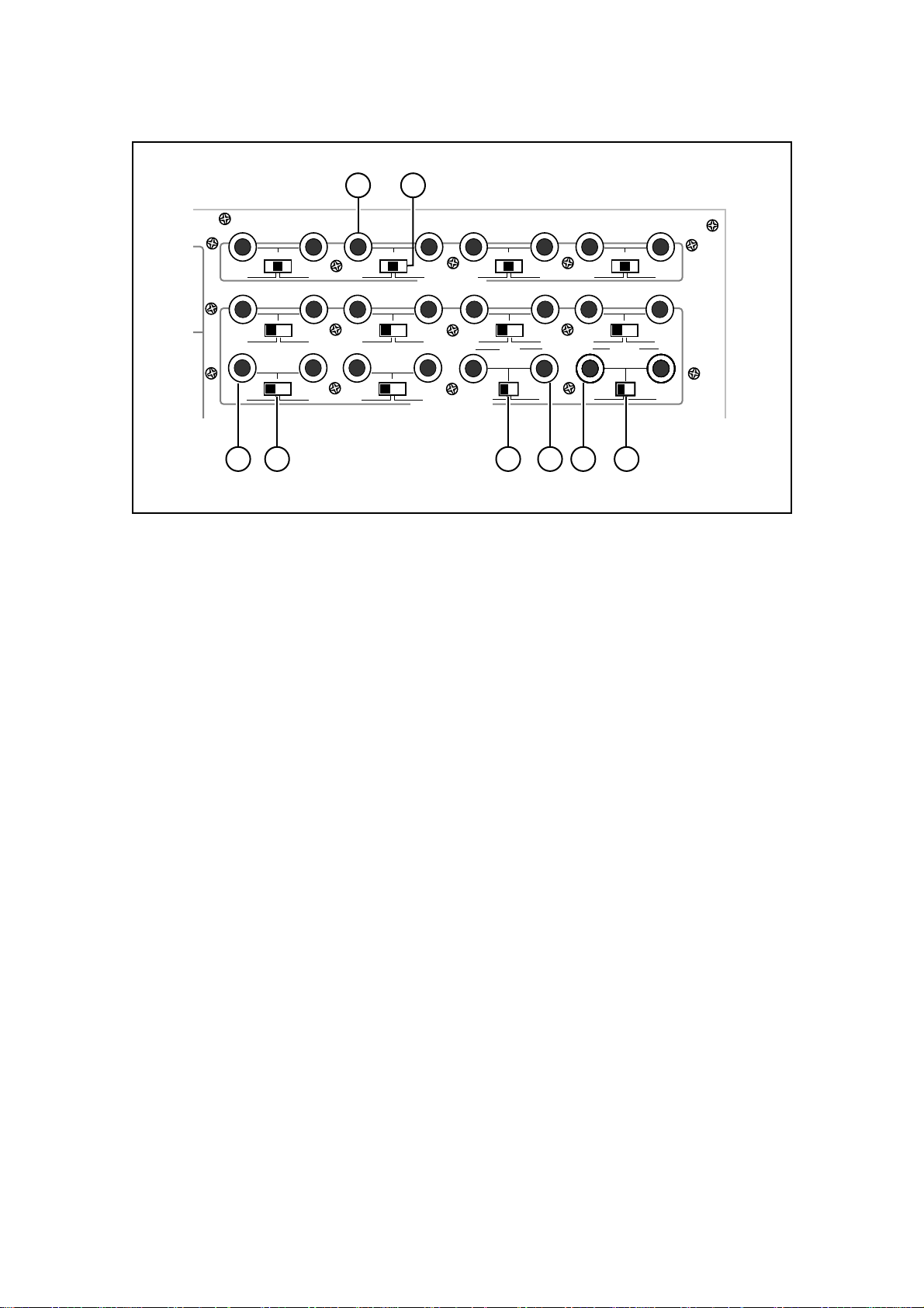
12) ANALOG OUTPUT (1 ~ 12) connectors
These 1/4 inch stereo phone jacks are used to output analog signals from the DR16pro. They
can be used balanced or unbalanced: Tip = hot, ring = cold, sleeve = ground.You set the
output gain for these connectors with the level switch (13). They can be set to LOW (-10 dBu)
or HIGH (+4 dBu).
13) Output level switches
These switches allow you to set the DR16pro output level. They can be set to LOW (-10 dBu)
or HIGH (+4 dBu). Output level switches are provided for each pair of channels: channels 1/
2, channels 3/4, channels 5/6, channels 7/8, channels 9/10, channels 1 1/12, channels 13/14,
and channels 15/16.
14) ANALOG OUTPUT 13, 14 - SEND 1/2 connectors
These 1/4 inch stereo phone jacks carry the individual analog tracks 13 and 14 or the two
effects or auxiliary sends in MIX mode. They can be used balanced or unbalanced: T ip = hot,
ring = cold, sleeve = ground. Y ou set the output gain for these connectors with the level switch
(13). They can be set to LOW (-10 dBu) or HIGH (+4 dBu).
15) ANALOG OUTPUT 15, 16 - MASTER L/R connectors
These 1/4 inch stereo phone jacks are used to output the individual analog tracks 15 and 16
or an analog stereo mix of the 16 tracks in MIX mode. This is an analog duplication of the
digital signal appearing at the DIGITAL I/O - MASTER OUT output jacks. They can be used
balanced or unbalanced: Tip = hot, ring = cold, sleeve = ground. You set the output level for
these connectors with the level switch (13). They can be set to LOW (-10 dBu) or HIGH (+4
dBu).
Page 21
 Loading...