


 Loading...
3Com® Unified Gigabit Wireless
PoE Switch 24
Quick Start Guide
Kurzanleitung
3CRUS2475
Copyright ® 2006 3Com Corporation. All rights reserved.
www.3Com.com
Part Number 10015246 Rev. AA
Published September 2006

About this Guide This guide is intended for use by those responsible for installing and setting up network equipment; consequently, it assumes a basic working knowledge of LANs (local area networks) and WLANs (wireless local area networks).
Diese Anleitung ist fur die Benutzung durch Netzwerkadministratoren vorgesehen, die fur die Installation und das einstellen von Netzwerkkomponenten verantwortlich sind; sie setzt Erfahrung bei der Arbeit mit LANs (Local Area Networks) und WLANs ( Wireless Local Area Networks) voranus.

3
Get the latest documentation and software for your 3Com switch
Thank you for purchasing a 3Com® Unified Gigabit Wireless PoE Switch 24. As part of our commitment to help you get the most out of your 3Com network equipment, we offer updated documentation and software on our website.
In addition to this Quick Start Guide, a detailed User Guide and a Command Line Interface Guide are also available on the 3Com website.
To obtain the most up-to-date user documentation and operating software for the 3Com Unified Switch 24, point your web browser to: www.3Com.com and select the “Support and Registration” link.
Please note that you must register your 3Com switch to receive software upgrades. To register, point your web browser to eSupport.3Com.com.
4 Get the latest documentation and software for your 3Com switch
5
Contents
About this Guide 2
Get the latest documentation and software
for your 3Com switch |
3 |
|
|
|||
1 Introducing the 3Com Unified Gigabit |
|
|||||
Wireless PoE Switch 24 |
7 |
|
|
|||
Overview of the Unified Gigabit Wireless PoE Switch 24 |
9 |
|||||
Unified Switching |
9 |
|
|
|
|
|
Wired Features |
10 |
|
|
|
|
|
Power over Ethernet (PoE) Features |
10 |
|
||||
Wireless Features |
10 |
|
|
|
|
|
2 Installing the 3Com Unified Switch 24 |
11 |
|||||
Checking the Package Contents |
11 |
|
|
|||
Choosing a Suitable Location |
11 |
|
|
|||
Aufstellen des Switch |
12 |
|
|
|
|
|
Free-Standing Installation 12 |
|
|
|
|||
Placing Units On Top of Each Other |
13 |
|
||||
Rack-Mount Installation |
13 |
|
|
|
|
|
Montagesatz Anweisungen |
14 |
|
|
|
||
Supplying Power |
15 |
|
|
|
|
|
Stromversorgung |
15 |
|
|
|
|
|
Checking for Correct Operation |
16 |
|
|
|||
3 Connecting to the 3Com Unified Switch 24 17
Before you begin 17 |
|
|
Connecting your computer to the switch |
17 |
|
Using the setup wizard |
18 |
|
Preparing the wireless network 20 |
|
|
Activating the Managed Access Points |
21 |
|
6
4 Preparing the Managed Access Points 23 |
|
Preparing the 7760 Access Point |
24 |
Preparing the 8760 Access Point |
25 |
Resetting Access Points 26 |
|
5 |
Upgrade your Switch to the Latest Software 27 |
|||||||
|
Loading Software into the Switch |
27 |
|
|
||||
|
Running a New Software Image |
28 |
|
|
||||
6 |
Restoring the Factory Default Settings |
29 |
||||||
7 |
Changing the Password |
30 |
|
|
||||
8 |
Using SFP Transceivers |
31 |
|
|
||||
|
Approved SFP Transceivers |
31 |
|
|
|
|||
|
Inserting and using an SFP Transceiver 31 |
|
|
|||||
|
Removing an SFP Transceiver |
32 |
|
|
||||
9 |
Troubleshooting |
33 |
|
|
|
|||
10 |
Technical Information |
35 |
|
|
||||
|
Related Standards 35 |
|
|
|
|
|
||
|
Environmental |
35 |
|
|
|
|
|
|
|
Physical |
36 |
|
|
|
|
|
|
|
Electrical |
36 |
|
|
|
|
|
|
11 |
Obtaining Support for your 3Com Product 37 |
|||||||
|
Register Your Product to Gain Service Benefits |
37 |
|
|||||
|
Solve Problems Online |
37 |
|
|
|
|
||
|
Purchase Extended Warranty and Professional Services |
38 |
||||||
|
Access Software Downloads |
38 |
|
|
||||
|
Contact Us |
38 |
|
|
|
|
|
|
|
Telephone Technical Support and Repair |
39 |
|
|||||
7
1 |
Introducing the |
3Com Unified Gigabit |
Wireless PoE Switch 24
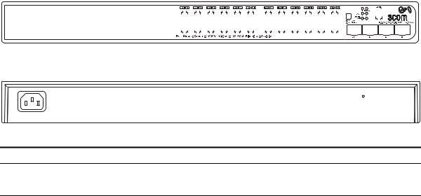
Figure 1 Front and Rear Views of the Unified Switch 24
|
|
|
|
|
|
|
|
|
|
|
|
|
|
|
|
|
|
|
|
|
|
1 & 2 |
3 56 7 8 |
|
|
||||||||||||||||||||||||||||||||||||
|
|
|
|
|
|
|
|
|
|
|
|
|
|
|
|
|
|
|
|
|
|
|
|
|
|
|
|
|
|
|
|
|
|
|
|
|
|
|
|
|
|
|
|
|
|
|
|
|
|
|
|
|
|
|
|
|
|
|
|
|
|
|
|
|
|
|
|
|
|
|
|
|
|
|
|
|
|
|
|
|
|
|
|
|
|
|
|
|
|
|
|
|
|
|
|
|
|
|
|
|
|
|
|
|
|
|
|
|
|
|
|
|
|
|
|
|
|
|
|
|
|
|
|
|
|
|
|
|
|
|
|
|
|
|
|
|
|
|
|
|
|
|
|
|
|
|
|
|
|
|
|
|
|
|
|
|
|
|
|
|
|
|
|
|
|
|
|
|
|
|
|
|
|
|
|
|
|
|
|
|
|
|
|
|
|
|
|
|
|
|
|
|
|
|
|
|
|
|
|
|
|
|
|
|
|
|
|
|
|
|
|
|
|
|
|
|
|
|
|
|
|
|
|
|
|
|
|
|
|
|
|
|
|
|
|
|
|
|
|
|
|
|
|
|
|
|
|
|
|
|
|
|
|
|
|
|
|
|
|
|
|
|
|
|
|
|
|
|
|
|
|
|
|
|
|
|
|
|
|
|
|
|
|
|
|
|
|
|
|
|
|
|
|
|
|
|
|
|
|
|
|
|
|
|
|
|
|
|
|
|
|
|
|
|
|
|
|
|
|
|
|
|
|
|
|
|
|
|
|
|
|
|
|
|
|
|
|
|
|
|
|
|
|
|
|
|
|
|
|
|
|
|
|
|
|
|
|
|
|
|
|
|
|
|
|
|
|
|
|
|
|
|
|
|
|
|
|
|
|
|
|
|
|
|
|
|
|
|
|
|
|
|
|
|
|
|
|
|
|
|
|
|
|
|
|
|
|
|
|
|
|
|
|
|
|
|
|
|
|
|
|
|
|
|
|
|
|
|
|
|
|
|
|
|
|
|
|
|
|
|
|
|
|
|
|
|
|
|
|
|
|
|
|
|
|
|
|
|
|
|
|
|
|
|
|
|
|
|
|
|
|
|
|
|
|
|
|
|
|
|
|
|
|
|
|
|
|
|
|
|
|
|
|
|
|
|
|
|
|
|
|
|
|
|
|
|
|
|
|
|
|
|
|
|
|
|
|
|
|
|
|
|
|
|
|
|
|
|
|
|
|
|
|
|
|
|
|
|
|
|
|
|
|
|
|
|
|
|
|
|
|
|
|
|
|
|
|
|
|
|
|
|
|
|
|
|
|
|
|
|
|
|
|
|
|
|
|
|
|
|
|
|
|
|
|
|
|
|
|
|
|
|
|
|
|
|
|
|
|
|
|
|
|
|
|
|
|
|
|
|
|
|
|
|
|
|
|
|
|
4
|
|
10 |
9 |
11 |
|
||||||||
|
|
|
|
|
|
|
|
|
|
|
|
|
|
|
|
|
|
|
|
|
|
|
|
|
|
|
|
|
|
|
|
|
|
|
|
|
|
|
|
|
|
|
|
|
|
|
|
|
|
|
|
|
|
|
|
|
|
|
|
|
|
|
|
|
|
|
|
|
|
|
|
|
|
|
|
|
|
|
|
|
|
|
|
Table 1 Features of the Unified Switch 24
Reference Description
110/100/1000 Mbps Network Ports (1–24): These autonegotiating ports determine the speed and duplex mode based on the connected device. Each port supports automatic MDI/MDIX detection and can be connected to a 10BASE-T, 100BASE-T, or 1000BASE-T device.
2LED Port Status Indicators: Each Network Port has a corresponding status indicator (1 to 24) that shows the status of the port’s network connection or PoE status (depending on the LED Status Select button).
Port Speed
■Green steady: 1000 Mbps link is present.
■Green flashing: 1000 Mbps traffic is present.
■Amber steady: 10/100 Mbps link is present.
■Amber flashing: 10/100 Mbps traffic is present.
■Off: Link is not present
PoE Status
■Green steady: PoE Power is being delivered to the port
■Off: No power is being delivered.

8 Introducing the 3Com Unified Gigabit Wireless PoE Switch 24
Table 1 Features of the Unified Switch 24 (continued)
Reference Description
3LED Status Select Button: This button sets the function of the Port LED indicators. When the button is in the out position, the port LEDs show the port speed (see #2 above). When the button is pressed in, the port LEDs show the PoE status.
4SFP Module Slots (21–24): The four Small Form Factor Pluggable (SFP) transceiver slots allow you to install an SFP transceiver (purchased separately). These ports support fiber Gigabit Ethernet short-wave (SX) and long-wave (LX) SFP transceivers in any combination.
When an SFP module is installed in a slot and is active, the associated RJ-45 port (21 to 24) of the same number is disabled.
5SFP Module Status Indicator: The four SFP status LED indicators show the state of the SFP module ports (21 to 24; see #4).
■Green: An SFP fiber module is present.
■Off: No fiber module is present.
When an SFP module is present, the fiber port activity is indicated by the corresponding LED over the RJ-45 port (21 to 24):
■Green steady: Fiber link is present.
■Green flashing: Fiber link traffic is present.
■Off: Link is not present
6Fan Indicator: Shows the status of the internal fans. Green steady: All fans are functioning properly. Amber steady: The switch is too hot.
Amber flashing: One or more fans have failed
7System Indicator: Shows the overall status of the switch.
■Green steady: The switch is powered-up and operating normally.
■Green flashing: The switch is undergoing self test, initialization, or downloading.
■Amber steady: The switch has detected a hardware malfunction such as temperature, fan, or voltage.
■Off: No power. The switch is off.
8Console Port: Allows you to connect a terminal and perform out-of-band management. The default communications settings are 19200 bps, 8 data bits, no Parity, 1 stop bit.
9Reset Button: Use the reset button to restore the switch to its factory defaults. See “Restoring the Factory Default Settings” on page 29.
10AC Power Input: Accepts 100–240 Vac, 50/60 Hz input power. The switch automatically adjusts to the input voltage.
11Feet: These are self-adhesive pads. You do not need to install them if you are rack-mounting the switch.

Overview of the Unified Gigabit Wireless PoE Switch 24 9
|
WARNING: The Network Ports are shielded RJ-45 data sockets. They |
|
cannot be used as standard traditional telephone sockets, or to connect |
|
the unit to a traditional PBX or public telephone network. Connect only |
|
RJ-45 data connectors, network telephony systems, or network |
|
telephones to these sockets. |
|
Either shielded or unshielded data cables with shielded or unshielded |
|
jacks can be connected to these data sockets. |
|
AVERTISSEMENT: Points d’accès RJ-45. Ceux-ci sont protégés par des |
|
prises de données. Ils ne peuvent pas être utilisés comme prises de |
|
téléphone conventionnelles standard, ni pour la connection de l’unité à |
|
un réseau téléphonique central privé ou public. Raccorder seulement |
|
connecteurs de données RJ-45, systèmes de réseaux de téléphonie ou |
|
téléphones de réseaux à ces prises. |
|
Il est possible de raccorder des câbles protégés ou non protégés avec des |
|
jacks protégés ou non protégés à ces prises de données. |
|
WARNHINWEIS: RJ-45-Porte. Diese Porte sind geschützte |
|
Datensteckdosen. Sie dürfen weder wie normale traditionelle |
|
Telefonsteckdosen noch für die Verbindung der Einheit mit einem |
|
traditionellem privatem oder öffentlichem Telefonnetzwerk gebraucht |
|
werden. Nur RJ-45-Datenanscluße, Telefonnetzsysteme or Netztelefone |
|
an diese Steckdosen anschließen. |
|
Entweder geschützte oder ungeschützte Buchsen dürfen an diese |
|
Datensteckdosen angeschlossen werden. |
|
|
Overview of the |
The 3Com® Unified Gigabit Wireless PoE Switch 24 is a versatile, |
Unified Gigabit |
easy-to-use unified switch. It is shipped ready for use, and no |
Wireless PoE |
configuration is necessary for operation as a basic Layer 2 Gigabit PoE |
Switch 24 |
switch. Additional features such as wireless can be configured easily using |
|
the Web-based user interface and setup wizard. Support for PoE and |
|
voice auto-prioritization makes the Unified Switch 24 a perfect starting |
|
point for IP telephony solutions. |
Unified Switching |
A unified switch is an all-in-one, fully-managed Ethernet switch |
|
combining gigabit, wireless, and PoE connectivity in a single platform. |
|
The Unified Switch 24 supports both wired Ethernet switching and |
|
centralized control for up to 24 wireless access points. |
10 Introducing the 3Com Unified Gigabit Wireless PoE Switch 24
Wired Features The switch has 24 shielded RJ-45, 10/100/1000 Mbps auto-negotiating ports and four Small Form Factor Pluggable (SFP) transceiver slots on the front panel.
The four SFP ports support fiber Gigabit Ethernet short-wave (SX) and long-wave (LX) SFP transceivers in any combination. This offers you the flexibility of using SFP transceivers to provide connectivity between the switch and a 1000 Mbps core network.
When an SFP port is in operation, the corresponding 10/100/1000BASE-T port (21 to 24) is disabled.
Power over Ethernet The switch can provide Power over Ethernet (PoE) to 802.3af compliant (PoE) Features devices over a Category 5 or better Ethernet cable. The switch can supply
up to 15.4 Watts of PoE to each of the 24 gigabit ports simultaneously. PoE (802.3af) is a self-configuring protocol. When you plug an 802.3af device into one of the gigabit ports on the switch, the switch will supply the required power to the device.
Wireless Features The 3Com Unified Switch 24 provides centralized control for up to 24 3Com 7760 or 8760 Access Points. Key wireless features include:
■Enterprise-grade WPA2/AES encryption
■802.1X authentication
■Centralized control for wireless security profiles
■Fast roaming
■Rogue AP detection and mitigation
■Multiple SSIDs per radio
■Traffic prioritization
■Load balancing
11
2 |
Installing the 3Com Unified |
Switch 24 |
Checking the
Package Contents
The Unified Switch 24 package includes the following items:
■One 3Com Unified Gigabit Wireless PoE Switch 24 unit
■One power cord
■Four standard height, self-adhesive rubber pads
■One mounting kit
■One warranty flyer and one safety flyer
■This Quick Start Guide
If any of the above items are damaged or missing, please contact your network supplier immediately.
WARNING: Before installing this switch, please read the safety flyer included with the unit.
GEFAHR: Lesen Sie bitte vor Installation des Switch das diesem Gerät beiliegende Sicherheitsblatt durch.
Choosing a Suitable The switch can be free-standing (see “Free-Standing Installation” on Location page 12), or it can be mounted in a 19-inch equipment rack using the
supplied mounting kit (see “Rack-Mount Installation” on page 13). When deciding where to position the switch, ensure that:
■It is accessible and cables can be connected easily.
■Cabling is away from sources of electrical noise. These include elevator shafts, microwave ovens, and air-conditioning units. Electromagnetic fields can interfere with the signals on copper cabling and introduce errors, and, consequently, slow down your network.
■Water or moisture cannot enter the case of the unit.

12Installing the 3Com Unified Switch 24
■Air flow around the unit and through the vents on the side of the case is not restricted. 3Com recommends that you provide a minimum of 25 mm (1 in.) clearance.
■The air is as free of dust as possible.
■Temperature operating limits are not likely to be exceeded. 3Com recommends that you install the switch in a clean, air conditioned environment.
When installing network equipment, it is always good practice to wear an antistatic wrist strap that is connected to a ground point. If one is not available, try to keep in contact with a grounded rack and avoid touching the unit's ports and connectors. Static discharge can cause reliability problems in your equipment.
Aufstellen des |
Bei der Entscheidung wo Sie den Switch positionieren, stellen Sie sicher |
Switch |
das: |
|
■ Der Switch zugänglich ist und die Kabel leicht angeschlossen werden |
|
können. |
|
■ Die Kabel nicht in der nähe von elektrischen Störquellen befinden. Das |
|
schließt Aufzugsschächte, Mikrowellen und Klimaanlagen ein. |
|
Elektromagnetische Felder können die Signale in den Kupferleitungen |
|
stören, und Fehler verursachen, was die Verlangsamung Ihres |
|
Netzwerkes zur Folge haben kann. |
|
■ Weder Wasser noch Feuchtigkeit in das Gehäuse eindringen kann. |
|
■ Die Luftzirkulation um den Switch und durch die Öffnungen des |
|
Gehäuses nicht behindert wird. 3Com empfiehlt das Sie 25mm (1 |
|
Inch) Zwischenraum sicherstellen. |
|
■ Die Luft so frei wie möglich von Staub ist. |
|
■ Es unwahrscheinlich ist das die Betriebstemperatur überschritten wird. |
|
3Com empfiehlt das Sie den Switch in einer sauberen, klimatisierten |
|
Umgebung installieren. |
|
|
Free-Standing |
Place the switch on a stable, flat surface where it is not likely to be |
Installation |
disturbed. Do not place objects on top of the switch or on top of a stack |
|
of switches. When locating the unit, you should take note of the |
|
guidelines given in “Choosing a Suitable Location” on page 11. |
Loading...