


 Loading...
User Guide
11 Mbps Wireless LAN Outdoor Bridge Solution
3CRWEASY96A
Complete building-to-building outdoor wireless LAN kit
http://www.3com.com/
http://support.3com.com/registration/frontpg.pl/
Published October, 2002
Document Version 1.0.1
3Com Corporation |
Copyright © 2002 3Com Corporation. All rights reserved. No part of this documentation may be |
5400 Bayfront Plaza |
reproduced in any form or by any means or used to make any derivative work (such as |
Santa Clara, California |
translation, transformation, or adaptation) without written permission from 3Com Corporation. |
95052-8145 |
3Com Corporation reserves the right to revise this documentation and to make changes in |
|
|
|
content from time to time without obligation on the part of 3Com Corporation to provide |
|
notification of such revision or change. |
|
3Com Corporation provides this documentation without warranty, term, or condition of any |
|
kind, either implied or expressed, including, but not limited to, the implied warranties, terms or |
|
conditions of merchantability, satisfactory quality, and fitness for a particular purpose. 3Com |
|
may make improvements or changes in the product(s) and/or the program(s) described in this |
|
documentation at any time. |
|
If there is any software on removable media described in this documentation, it is furnished |
|
under a license agreement included with the product as a separate document, in the hard copy |
|
documentation, or on the removable media in a directory file named LICENSE.TXT |
|
or!LICENSE.TXT. If you are unable to locate a copy, please contact 3Com and a copy will be |
|
provided to you. |
|
UNITED STATES GOVERNMENT LEGEND |
|
If you are a United States government agency, then this documentation and the software |
|
described herein are provided to you subject to the following: |
|
All technical data and computer software are commercial in nature and developed solely at |
|
private expense. Software is delivered as “Commercial Computer Software” as defined in DFARS |
|
252.227-7014 (June 1995) or as a “commercial item” as defined in FAR 2.101(a) and as such is |
|
provided with only such rights as are provided in 3Com’s standard commercial license for the |
|
Software. Technical data is provided with limited rights only as provided in DFAR 252.227-7015 |
|
(Nov 1995) or FAR 52.227-14 (June 1987), whichever is applicable. You agree not to remove or |
|
deface any portion of any legend provided on any licensed program or documentation |
|
contained in, or delivered to you in conjunction with, this User Guide. |
|
Unless otherwise indicated, 3Com registered trademarks are registered in the United States and |
|
may or may not be registered in other countries. |
|
3Com and SuperStack are registered trademarks of 3Com Corporation. Wi-Fi is a trademark of |
|
the Wireless Ethernet Compatibility Alliance. |
|
All other company and product names may be trademarks of the respective companies with |
|
which they are associated. |
|
EXPORT RESTRICTIONS: This product contains Encryption and may require US and/or Local |
|
Government authorization prior to export or import to another country. |

Contents
Introduction
Product Overview 7 |
|
Point-to-Point Topology |
7 |
Point-to-Multipoint Topology 8 |
|
Basic Operating Modes |
9 |
Planning the Installation
Installation Guidelines |
10 |
|
|
Proper Grounding |
11 |
|
|
Alignment |
11 |
|
|
Polarization |
11 |
|
|
Thermal Conditions |
12 |
|
|
Restrictions on Antenna Use |
12 |
||
Administration Requirements |
13 |
||
Installing the Bridge
Mounting the Bridge to a Mast |
14 |
Connecting the Bridge to the LAN |
15 |
Installing Software Utilities 16 |
|
Establishing Wireless Association |
17 |
Configuring the Bridge
Using the Device Manager 18
Launching a Wireless Device Configuration 18 Using the Pre-IP Configuration Wizard 20
Saving Configuration Changes |
20 |
Changing System Properties |
21 |
Setting IP Network Properties |
22 |
Setting up Protocol and Port Filtering 23

Setting Wireless Network Properties 24 Setting Advanced Performance Properties 26 Setting up an Ad Hoc Network 27
Setting up an Access Point Infrastructure Network 28
Changing Security Settings |
|
29 |
|
|
No Security (Open System) |
30 |
|
||
40-bit Shared Key (Wi-Fi) |
|
30 |
|
|
128-bit Shared Key |
31 |
|
|
|
128-bit Dynamic Security Link 31 |
|
|||
Setting up the Wireless Network Login |
31 |
|||
Resetting the Bridge |
32 |
|
|
|
Restoring a Bridge to Factory Defaults 32 |
||||
Upgrading the System |
32 |
|
|
|
Changing the Administration Password |
33 |
|||
Backing up a Configuration |
|
33 |
|
|
Restoring a Configuration |
34 |
|
||
Viewing the Client List |
34 |
|
|
|
Resetting Statistics Listings |
35 |
|
||
Clearing the Client List |
35 |
|
||
Viewing Connection Status |
|
35 |
|
|
Viewing the System Summary |
35 |
|
||
Interoperating with Third-Party Equipment |
35 |
|||
Troubleshooting
Diagnosing Problems 36 |
|
Disconnecting the Bridge |
38 |
Uninstalling Software and Documentation 38 |
|
Upgrading Bridge Firmware |
38 |
Technical Support
Online Technical Services 39
Support from Your Network Supplier 40 Support from 3Com 40
Returning Products for Repair 42

Regulatory Compliance Information
Index

1 INTRODUCTION
PRODUCT OVERVIEW
The 3Com 11 Mbps Wireless LAN Outdoor Bridge Solution is a complete building-to-building outdoor wireless LAN kit that eliminates the need to evaluate, purchase and assemble separate components. The convenient package includes the 3Com 11 Mbps Wireless LAN Building-to-Building Bridge with an integrated high-power directional antenna and power-over-Ethernet cable in a durable, weatherproof enclosure—everything you need for an easy-to-manage building-to-building wireless LAN solution.
This all-in-one wireless LAN solution delivers three to four times the bandwidth of T1 links, with significantly lower operational costs. The wireless bridge lets you connect cross-campus buildings, or portable or temporary classrooms, at distances up to 16 kilometers (10 miles). The building-to-building bridge interoperates seamlessly with other Wi-Fi certified access points in large multi-vendor environments.
The 3Com bridge can be used in two types of wireless network topologies:
■Point-to-point
■Point-to-multipoint
This guide explains these network topologies and their components, and explains how to install, configure, and administer the 3Com bridge.
POINT-TO-POINT TOPOLOGY
Point-to-point topology is the simplest way to use the 3Com bridge, and it offers the highest performance level. Two 3Com outdoor bridges form a direct wireless association between the wired LANs in two remote buildings. See the following diagram of the point-to-point topology.
7

POINT-TO-MULTIPOINT TOPOLOGY
Point-to-multipoint topology allows communication among three or more buildings. In one building, an access point equipped with an omnidirectional antenna provides wireless association among the wired LANs in several other buildings with 3Com outdoor bridges installed.
If a 3Com 11 Mbps Wireless LAN Access Point 8000 is used, this topology can connect wired LANs over distances up to 16 kilometers (10 miles).
NOTE: If an access point from another Wi-Fi compliant manufacturer is used, the WLAN can extend up to 3 kilometers (2 miles).
8
BASIC OPERATING MODES
Two operating modes relate to the basic WLAN topologies:
■Ad hoc mode. This is the basis for point-to-point topology. Operating in ad hoc mode, two outdoor bridges can associate without an access point, allowing the LANs to which they are connected to communicate.
■Access Point (Infrastructure) mode. This is the basis for point-to-multipoint topology. Operating in access point mode, multiple 3Com outdoor bridges act as clients to an Access Point 8000 or a Wi-Fi compliant access point from another manufacturer.
9

2 PLANNING THE INSTALLATION
The following items are required for installation:
■For a point-to point configuration, two 3Com outdoor bridges.
■For a point-to-multipoint configuration, one 3Com 11Mbps Wireless LAN Access Point 8000 (or other Wi-Fi compliant access point) with an omnidirectional antenna for one building, and one 3Com outdoor bridge for each other building.
■Mounting hardware (supplied with each bridge)
■Properly grounded outdoor mast or wall mount
■Lightning arrestor properly grounded at each building in the topology.
■3Com Integrated Power-over-Ethernet power supply.
If your LAN equipment complies with the IEEE 802.3af power-over-Ethernet standard, you can connect directly to the equipment, and the power supply is not needed.
■ Outdoor rated category 5 Ethernet cable (such as 3CWE487)
The cable must be long enough to reach the power-over-Ethernet LAN port.
If you use the power supply, you need an additional length of Ethernet cable to connect the bridge to the LAN.
INSTALLATION GUIDELINES
NOTE: Only professional network personnel should install the bridge, cables, and antennas.The importance of this is paramount, for the sake of compliance with FCC and other regulatory issues, as well as for the safety of people and equipment.
The 11 Mbps Wireless LAN Outdoor Bridge Solution is housed in a durable, watherproof enclosure and is specifically designed for outdoor use in most climates. Optimal performance can be maintained at outdoor temperature ranges from -20˚ C to 50˚C (-4˚F to 122˚F). It is extremely important that the unit not be
10
mounted in any area where it could be vulnerable to extreme or hazardous conditions of any kind.
PROPER GROUNDING
To ensure the physical safety of anyone near the bridge and to prevent damage to the unit, follow the building codes for antenna installations in your area. Make certain that bridges and masts are appropriately grounded to prevent injury or damage from lightning strikes.
A lightning arrestor, properly grounded and installed at each building in the topology, will protect networking equipment in the building, as well as the people working there, from lightning-induced surges that travel on Ethernet cables.
CAUTION: A lightning arrestor will not prevent damage from direct lightning strikes. This is why it is extremely important to ensure that the bridge is installed at least 1 meter (3 feet) below the top of the mast.
ALIGNMENT
Position each bridge so that they are aimed at each other wherever possible. While maintaining a direct line of sight between antennas helps to ensure a strong signal, it is not strictly necessary, nor is it always possible. Conditions such as long distances, mountainous regions, and architectural barriers will make a direct line of sight nearly impossible to achieve.
In a campus setting, where buildings are short distances apart, and especially in a point-to-point configuration, align each unit to point at the antenna with which it will communicate. If you place two units at different heights, tilt them up or down toward each other for optimal signal strength.
POLARIZATION
Polarization is a physical phenomenon of radio signal propagation. In general, any two antennas that are to communicate with each other must be set for the same horizontal or vertical polarization. If polarization on both antennas does not match—a situation called cross-polarization—the link will either work poorly or not at all. Follow these polarization guidelines:
■Vertical polarization is required for point-to-multipoint configuration and is preferred for point-to-point configuration.
11
■For point-to-multipoint configurations, the omnidirectional antenna connected to the access point should be vertically aligned in relation to the ground.
■Unidirectional antennas that link with omnidirectional antennas should always be oriented for vertical polarization.
Bridges should be identically polarized, either horizontally or vertically.
THERMAL CONDITIONS
As mentioned in a previous section, optimal performance is maintained at temperature ranges between -20˚C to 50˚C (-4˚F to 122˚F).
RESTRICTIONS ON ANTENNA USE
The following restrictions apply to the use of the bridge’s 18 dBi antenna:
CAUTION: FCC regulations require that in the United States, use of channels 12 and 13 in conjunction with an 18 dBi antenna is allowed only at very reduced power.
■The highest allowable power level will be set automatically when the country selection is made from the pulldown menu in the configuration tool.
12
■To comply with power restrictions on 18 dBi antennas, bridges must be separated by at least 200 meters (218 yards).
ADMINISTRATION REQUIREMENTS
To use the administration tool, which helps you select 3Com wireless LAN devices and launch their configuration management systems, you need a computer running one of the following operating systems and one of the
following browsers:
■Operating Systems: Windows XP, Windows 2000, Windows NT 4.0, Windows Me, Windows 98
■Browsers: Netscape 6.0 or later, Internet Explorer 5.0 or later.
(If you want to configure the bridge using a non-Windows computer, refer to the readme file on the 3Com CD.)
13
3 INSTALLING THE BRIDGE
The bridge can be placed in any outdoor location as described in Installation Guidelines.
Note: Only professional network personnel should install the bridge unit, antennas and cables. This helps to ensure compliance with all local and national buiding codes, regulatory restrictions, FCC rules, and the safety of people and equipment.
MOUNTING THE BRIDGE TO A MAST
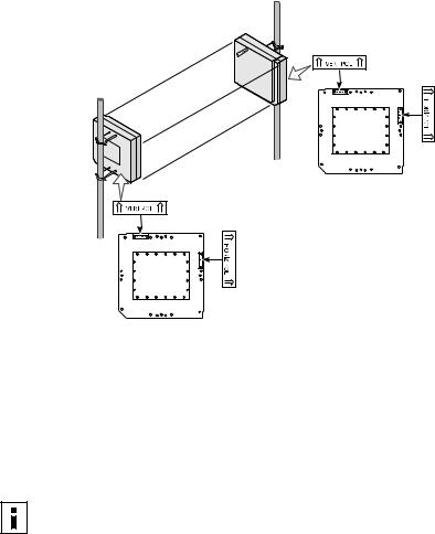
Refer to the adjustable mount instruction sheet that comes with the bridge mounting hardware, and review the illustration below.
Mast should extend
above bridge 1 meter (3 ft).
Outdoor Ethernet cable 3CWE487
Bridge may be installed to freestanding or roof mounted mast.
To indoor connection
14

CAUTION: As shown in the illustration, avoid damage from direct lightning strikes by mounting the bridge at least 1 Meter (3 feet) below the top of the mast.
WARNING: Do not install the bridge near overhead power lines, electric light or power circuits, or where it can come into contact with such circuits. When installing the bridge, do not come into contact with such circuits, which can cause serious injury or death. Follow local and national codes for proper installation and grounding of antennas.
WARNING: Do not install the bridge or connect and disconnect cables during periods of lightning activity.
Make sure that all bridges are properly oriented for polarization as described in Polarization. Use the polarization indicators on the antenna panel to guide orientation. VERT POL indicates vertical polarization and HORIZ POL indicates horizontal polarization.
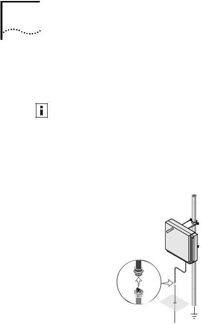
CONNECTING THE BRIDGE TO THE LAN
The bridge complies with the IEEE 802.3af power-over-Ethernet standard. It receives power over an Ethernet cable. There are two ways to supply power to the bridge:
■Use the 3Com Integrated Power-over-Ethernet power supply. In this case, you need to supply a second Ethernet cable to connect to the wired LAN.
The power supply can be located at any point between the bridge and the LAN access port, wherever a convenient power outlet exists.
When connecting the power, be sure to connect the cable to the port labeled “To Access Point” on the power supply.
Use another standard Ethernet cable to connect the bridge to an Ethernet network. Be sure that the Ethernet cable connected to the LAN port is plugged into the “To Hub/Switch” port on the power supply.
Caution: To avoid damaging other components connected to the network, make sure that the Ethernet cable connected to the LAN port is plugged into the “To Hub/Switch” port on the power supply (not the “To Access Point” port).
■Connect the bridge directly to your own power-over-Ethernet hub or switch. In this case, your equipment must also comply with the IEEE 802.3af standard. If your LAN equipment complies with the IEEE 802.3af power-over-Ethernet standard, you can connect the bridge directly to a LAN port.
15
Loading...