


 Loading...
 3Com® VCX™ V7111
VoIP Gateway
Installation Guide
System Release 4.8
http://www.3com.com
Part Number 900-0391-01 Rev AB
Published December 2006
3Com Corporation, 350 Campus Drive, Marlborough MA 01752-3064
Copyright © 2003 - 2006, 3Com Corporation. All rights reserved.
No part of this documentation may be reproduced in any form or by any means or used to make any derivative work (such as translation, transformation, or adaptation) without written permission from 3Com Corporation.
3Com Corporation reserves the right to revise this documentation and to make changes in content from time to time without obligation on the part of 3Com Corporation to provide notification of such revision or change.
3Com Corporation provides this documentation without warranty, term, or condition of any kind, either implied or expressed, including, but not limited to, the implied warranties, terms, or conditions of merchantability, satisfactory quality, and fitness for a particular purpose. 3Com may make improvements or changes in the product(s) and/or the program(s) described in this documentation at any time.
If there is any software on removable media described in this documentation, it is furnished under a license agreement included with the product as a separate document, in the hardcopy documentation, or on the removable media in a directory file named LICENSE.TXT or !LICENSE.TXT. If you are unable to locate a copy, please contact 3Com and a copy will be provided to you.
UNITED STATES GOVERNMENT LEGEND
If you are a United States government agency, then this documentation and the software described herein are provided to you subject to the following:
All technical data and computer software are commercial in nature and developed solely at private expense. Software is delivered as “Commercial Computer Software” as defined in DFARS 252.227-7014 (June 1995) or as a “commercial item” as defined in FAR 2.101(a) and as such is provided with only such rights as are provided in 3Com’s standard commercial license for the Software. Technical data is provided with limited rights only as provided in DFAR 252.227-7015 (Nov 1995) or FAR 52.227-14 (June 1987), whichever is applicable. You agree not to remove or deface any portion of any legend provided on any licensed program or documentation contained in, or delivered to you in conjunction with, this guide.
Unless otherwise indicated, 3Com registered trademarks are registered in the United States and may or may not be registered in other countries.
3Com, the 3Com logo, NBX, and SuperStack are registered trademarks of 3Com Corporation. NBX NetSet, pcXset, and VCX are trademarks of 3Com Corporation.
Adobe is a trademark and Adobe Acrobat is a registered trademark of Adobe Systems Incorporated. Microsoft, Windows, Windows 2000, Windows NT, and Microsoft Word are registered trademarks of Microsoft Corporation.
All other company and product names may be trademarks of the respective companies with which they are associated
2 |
3Com VCX V7111 Analog Gateway Installation Guide |

CONTENTS
ABOUT THIS GUIDE 7
How to Use This Guide 8
Conventions 9
Documentation Comments 9
Notices 9
WEEE EU Directive 9
Abbreviations and Terminology 10
CHAPTER 1: QUICK START 11
CHAPTER 2: INSTALLING THE V7111 13
Installing the V7111 13
Unpacking 13
Package Contents 14
19-inch Rack Installation Package 14
Mounting the V7111 14
Cabling the V7111 16
Installing the V7111 24-PORT 18
Unpacking 19
Package Contents 19
Mounting the V7111 24-PORT 19
Cabling the V7111 24-PORT 21
CHAPTER 3: CONFIGURING THE V7111 25
Assigning the V7111 IP Address 25
Assigning an IP Address Using HTTP 26
Assigning an IP Address Using BootP 27
Assigning an IP Address Using the Voice Menu Guidance 28
Assigning an IP Address Using the CLI 29
Restoring Networking Parameters to Their Initial State 30
Accessing the Embedded Web Server 31
3Com VCX V7111 Analog Gateway Installation Guide |
3 |

Basic Control Protocol Parameters 32
Configuring Basic MGCP Parameters 32
Configuring Basic H.323 Parameters 34
Configuring Basic SIP Parameters 36
Example of Connecting Two xxx Devices 38
CHAPTER 4: CHANGING THE V7111 USERNAME AND PASSWORD 39 CHAPTER 5: RESTORING AND BACKING UP THE V7111 CONFIGURATION 41 CHAPTER 6: MONITORING THE V7111 43
Monitoring the V7111 Front Panel LEDs 43
Monitoring the V7111 Channels 44
CHAPTER 7: UPGRADING THE V7111 47
Software Upgrade Wizard 47
Updating the Auxiliary Files 53
CHAPTER 8: REGULATORY INFORMATION 57
V7111 FXS Regulatory Information 57
Safety Notice 59
Telecommunication Safety 59
FCC Statement 59
V7111 FXO Regulatory Information 60
Safety Notice 61
Industry Canada Notice 61
Network Compatibility 62
Telecommunication Safety 62
MP-1xx FXO Notice 62
FCC Statement 62
V7111 FXS +FXO Regulatory Information 64
Safety Notice 65
Telecommunications Safety 66
FCC Statement 66
V7111 24-PORT 67
Safety Notice 68
Telecommunication Safety 69
4 |
3Com VCX V7111 Analog Gateway Installation Guide |

FCC Statement 69
OBTAINING SUPPORT FOR YOUR 3COM PRODUCT 71
Customer Support 71
3Com VCX V7111 Analog Gateway Installation Guide |
5 |
6 |
3Com VCX V7111 Analog Gateway Installation Guide |

ABOUT THIS GUIDE
This guide describes the installation of the V7111 VoIP media gateways. The model numbers that this manual supports are:
VCX V7111 VoIP Gateway 2 FXS (3CRVG71115-07)
VCX V7111 VoIP Gateway 4 FXS (3CRVG71110-07)
VCX V7111 VoIP Gateway 8 FXS (3CRVG71111-07)
VCX V7111 VoIP Gateway 24 FXS (3CRVG71112-07)
VCX V7111 VoIP Gateway 4 FXO (3CRVG71113-07)
VCX V7111 VoIP Gateway 8 FXO (3CRVG71114-07)
VCX V7111 VoIP Gateway 2 FXS, 2FXO (3CRVG71116-07)
VCX V7111 VoIP Gateway 4 FXS, 4 FXO (3CRVG71117-07)
Information contained in this document is believed to be accurate and reliable at the time of printing. However, because of on-going product improvements and revisions, 3Com cannot guarantee the accuracy of printed material after the Date Published nor can it accept responsibility for errors or omissions. Updates to this document and other documents can be viewed by registered Technical Support customers at www.3Com.com under Support / Product Documentation.
When viewing this manual on CD, Web site or on any other electronic copy, all cross-references are hyperlinked. Click on the page or section titles (shown in blue) to reach the individual cross-referenced item directly. To return back to the point from where you accessed the cross-reference, press the ALT and ◄ keys.
3Com VCX V7111 Analog Gateway Installation Guide |
7 |

How to Use This Guide
This book covers these topics:
Chapter 1: Quick Start
Chapter 2: Installing the V7111
Chapter 3: Configuring the V7111
Chapter 4: Changing the V7111 Username and Password
Chapter 5: Restoring and Backing Up the V7111 Configuration
Chapter 6: Monitoring the V7111
Chapter 7: Upgrading the V7111
Chapter 8: Regulatory Information
8 |
3Com VCX V7111 Analog Gateway Installation Guide |
Conventions
Table 1 lists conventions that are used throughout this guide.
Table 1 |
Notice Icons |
|
|
|
|
Icon |
Notice Type |
Description |
|
|
|
|
Information note |
Information that describes important features or |
|
|
instructions. |
|
|
|
|
Caution |
Information that alerts you to potential loss of data or |
|
|
potential damage to an application, device, system, |
|
|
or network. |
|
|
|
|
Warning |
Information that alerts you to potential personal injury |
|
|
or death. |
|
|
|
Documentation Comments
Your suggestions are important to us because we want to make our documentation more useful to you.
Please send e-mail comments about this guide or any of the V7111 documentation and Help systems to:
VOICE_TECHCOMM_COMMENTS@3com.com
Please include the following information with your comments:
Document title
Document part number (usually found on the front page)
Page number
Your name and organization (optional)
See the Appendix Obtaining Support for Your Product for how to register your product and get support from 3Com.
Notices
WEEE EU Directive
Pursuant to the WEEE EU Directive, electronic and electrical waste must not be disposed of with unsorted waste. Please contact your local recycling authority for disposal of this product.
3Com VCX V7111 Analog Gateway Installation Guide |
9 |
Abbreviations and Terminology
Each abbreviation, unless widely used, is spelled out in full when first used. Only industrystandard terms are used throughout this manual. Hexadecimal notation is indicated by 0x preceding the number.
Where "network" appears in this manual, it means LAN, WAN, etc. accessed via the gateway's Ethernet interface.
FXO (Foreign Exchange Office) is the interface replacing the analog telephone and connects to a Public Switched Telephone Network (PSTN) line from the Central Office (CO) or to a Private Branch Exchange (PBX). The FXO is designed to receive line voltage and ringing current, supplied from the CO or the PBX (just like an analog telephone). An FXO VoIP gateway interfaces between the CO/PBX line and the Internet.
FXS (Foreign Exchange Station) is the interface replacing the Exchange (i.e., the CO or the PBX) and connects to analog telephones, dial-up modems, and fax machines. The FXS is designed to supply line voltage and ringing current to these telephone devices. An FXS VoIP gateway interfaces between the analog telephone devices and the Internet.
WARNING:
Ensure that you connect FXS ports to analog telephone or to PBX-trunk lines only and FXO ports to Central Office (CO)/PBX lines only.
The V7111 is supplied as a sealed unit and must only be installed or serviced by qualified service personnel.
10 |
3Com VCX V7111 Analog Gateway Installation Guide |
CHAPTER 1: QUICK START
This guide provides you with information on how to install the V7111 for the first time. Prior knowledge of IP networks is preferred.
Refer to the configuration procedures, outlined in Figure 1, for information on how to install, initialize, configure the device and make calls. For detailed information on how to fully configure the gateway, refer to the VCX V7111 VoIP Gateway User Manual.
Figure 1 Required Steps to Install the V7111
Unpack the V7111
Mount the V7111
Cable the V7111
Assign the V7111 IP Address
Assign the V7111 IP Address
Configure the Parameters
3Com VCX V7111 Analog Gateway Installation Guide |
11 |
12 |
3Com VCX V7111 Analog Gateway Installation Guide |

CHAPTER 2: INSTALLING THE V7111
This section provides information on the installation procedure for the V7111 (see Installing the V7111) and the V7111 24-PORT. For information on configuring the gateway, see Chapter 3: Configuring the V7111.
WARNING:
The V7111 is supplied as a sealed unit and must only be installed and serviced by qualified service personnel.
Units providing power sockets with three pins must be connected by service personnel to a socket-outlet with a protective earthing connection.
Installing the V7111
To install the V7111, follow these 4 steps:
1Unpack the V7111 (see Unpacking).
2Check the package contents (see Package Contents).
3Mount the V7111 (see Mounting the V7111).
4Cable the V7111 (see Cabling the V7111).
After connecting the V7111 to the power source, the Ready and Power LEDs on the front panel turn to green (after a self-testing period of about 2 minutes). Any malfunction in the startup procedure changes the Fail LED to red and the Ready LED is turned off (see Table10 for details on the V7111 LEDs).
When you have completed the above relevant sections you are then ready to start configuring the gateway (see Chapter 3: Configuring the V7111).
Unpacking
To unpack the V7111, follow these 6 steps:
1Open the carton and remove the packing materials.
2Remove the V7111 gateway from the carton.
3Check that there is no equipment damage.
4Check, retain and process any documents.
3Com VCX V7111 Analog Gateway Installation Guide |
13 |
5Notify 3Com or your local supplier of any damage or discrepancies.
6Retain any diskettes or CDs.
Package Contents
Ensure that in addition to the V7111, the package contains:
AC power cable.
Small plastic bag containing four anti-slide bumpers for desktop installation.
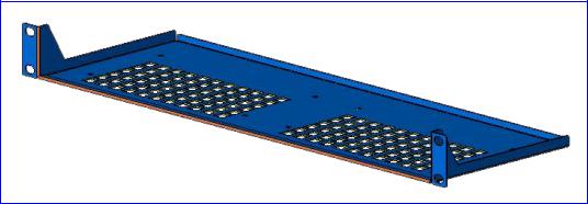
19-inch Rack Installation Package
Additional option is available for installing the V7111 in a 19-inch rack. The 19-inch rack installation package contains a single shelf (shown in Figure 2) and eight shelf-to-device screws.
Figure 2 19-inch Rack Shelf
Mounting the V7111
The V7111 can be mounted on a desktop (see Mounting the V7111 on a Desktop), on a wall (see Mounting the V7111 on a Wall) or installed in a standard 19-inch rack (see Installing the V7111 in a 19-inch Rack).
Figure 3 describes the V7111 base.
14 |
3Com VCX V7111 Analog Gateway Installation Guide |

Figure 3 View of the V7111 Base
3 2
1
Table 2 |
View of the V7111 Base |
|
|
|
|
|
Item # |
Functionality |
|
|
|
1 |
Square slot used to attach anti-slide bumpers (for desktop mounting) |
|
|
|
|
2 |
Oval notch used to attach the V7111 to a wall |
|
|
|
|
3 |
Screw opening used to attach the V7111 to a 19-inch shelf rack |
|
|
|
|
Mounting the V7111 on a Desktop
Attach the four (supplied) anti-slide bumpers to the base of the V7111 (see item #1 in Figure 3) and place it on the desktop in the position you require.
Mounting the V7111 on a Wall
To mount the V7111 on a wall, follow these 4 steps:
1Drill four holes according to the following dimensions:
Side-to-side distance 140 mm.
Front-to-back distance 101.4 mm.
2Insert a wall anchor of the appropriate size into each hole.
3Fasten a DIN 96 3.5X20 wood screw (not supplied) into each of the wall anchors.
4Position the four oval notches located on the base of the V7111 (see item #2 in Figure 3) over the four screws and hang the V7111 on them.
3Com VCX V7111 Analog Gateway Installation Guide |
15 |
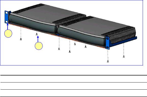
Installing the V7111 in a 19-inch Rack
The V7111 is installed in a standard 19-inch rack by placing it on a shelf preinstalled in the rack. The 19-inch rack shelf is not supplied in the standard package kit, but can be ordered separately. For ordering and pricing, please contact your network distributor.
Figure 4 V7111 Rack Mount
1
2
Table 3 V7111 Rack Mount
Item # |
Functionality |
1Standard rack holes used to attach the shelf to the rack
2Eight shelf-to-device screws
To install the V7111 in a 19-inch rack, follow these 3 steps:
1Use the shelf-to-device screws found in the package to attach one or two V7111 devices to the shelf.
2Position the shelf in the rack and line up its side holes with the rack frame holes.
3Use four standard rack screws (not supplied) to attach the shelf to the rack.
Cabling the V7111
Figure 5 illustrates the rear layout of the V7111. Table 4 lists and describes the rear panel connectors and button on the V7111.
Cable your V7111 according to each section of Table 5
16 |
3Com VCX V7111 Analog Gateway Installation Guide |
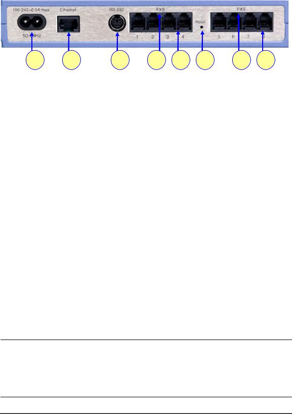
Figure 5 V7111 Rear Panel Connectors
|
|
|
1 |
2 |
3 |
4 |
5 |
6 |
4 |
5 |
Table 4 |
V7111 Rear Panel Component Descriptions |
|
|
|
|
|||||
|
|
|
|
|
|
|
|
|
|
|
|
|
Item # |
Label |
|
Component Description |
|
|
|
|
|
|
|
|
|
|
|
|
|
|
||
1 |
100-240~0.3A max. |
AC power supply socket |
|
|
|
|
||||
|
|
|
|
|
|
|
|
|
|
|
2 |
Ethernet |
|
10/100 Base-TX Uplink port |
|
|
|
|
|||
|
|
|
|
|
|
|
||||
3 |
RS-232 |
|
RS-232 status port (requires a DB-9 to PS/2 adaptor) |
|
||||||
|
|
|
|
|
|
|||||
4 |
FXS or FXO |
A label that distinguishes between FXS & FXO devices |
|
|||||||
|
|
|
|
|
|
|
|
|
||
5 |
-- |
|
2, 4 or 8 FXS / FXO ports |
|
|
|
|
|||
|
|
|
|
|
|
|
|
|
|
|
6 |
Reset |
|
Reset button |
|
|
|
|
|
||
|
|
|
|
|
|
|
|
|||
Table 5 |
V7111 Cables and Cabling Procedure |
|
|
|
|
|
||||
|
|
|
|
|
|
|
|
|
|
|
|
|
Cable |
|
Cabling Procedure |
|
|
|
|
|
|
|
|
|
|
|
||||||
|
|
|
|
Connect the Ethernet connection on the V7111 directly to the network using a |
||||||
|
|
RJ-45 Ethernet |
standard RJ-45 Ethernet cable. For connector pinouts, see Figure 6. |
|
||||||
|
|
|
cable |
Note that when assigning an IP address to the V7111 using HTTP (under Step 1 in |
||||||
|
|
|
Assigning an IP Address Using HTTP), you may be required to disconnect this |
|||||||
|
|
|
|
|||||||
|
|
|
|
cable and re-cable it differently. |
|
|
|
|
|
|
|
|
|
|
|
|
|
||||
|
|
|
|
Connect the RJ-11 FXS connectors to fax |
|
Ensure that FXS and FXO ports are |
||||
|
|
RJ-11 two-wire |
machines, modems, or phones. |
|
|
connected to the correct devices, |
||||
|
|
|
|
|
|
|
|
|
||
|
|
|
|
|
|
otherwise damage can occur. |
||||
|
|
telephone cords Connect the RJ-11 FXO connectors to |
|
|||||||
|
|
|
|
telephone exchange analog lines or PBX |
|
The RJ-11 pinouts are described in |
||||
|
|
|
|
extensions. |
|
|
|
Figure 6). |
|
|
RS-232 serial cable
Using a standard RS-232 straight cable (not a cross-over cable) with DB-9 connectors, connect the V7111 RS-232 port (using a DB-9 to PS/2 adaptor) to either COM1 or COM2 RS-232 communication port on your PC. The pinouts of the PS/2 connector are shown in Figure 8.
A PS/2 to DB-9 adaptor is not included with the V7111 package. For the PS/2 to DB-9 pinouts, see Figure 9.
AC Power cable Connect the V7111 power socket to the mains.
3Com VCX V7111 Analog Gateway Installation Guide |
17 |
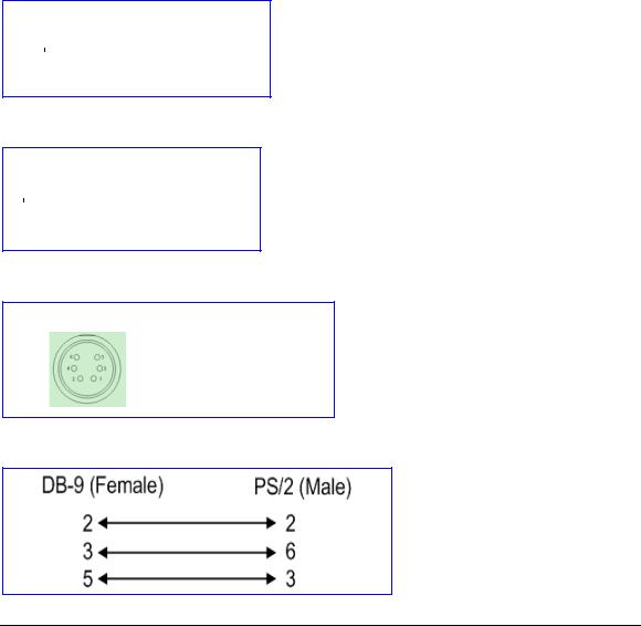
Figure 6 RJ-45 Ethernet Connector Pinouts
RJ-45 Connector and Pinout
1 2 3 4 5 6 7 8 |
|
1 |
- Tx+ |
4, 5, 7, 8 |
|
|
2 |
- Tx- |
not |
|
|
3 |
- Rx+ |
|
|
|
connected |
||
|
|
6 |
- Rx- |
|
|
|
|
||
|
|
|
|
|
Figure 7 Phone Connector Pinouts
RJ-11 Connector and Pinout
1 2 3 4 |
|
1 - |
Not connected |
||
|
|
|
|
||
|
|
|
|
2 - |
Tip |
|
|
|
|
||
|
|
|
|
3 - |
Ring |
|
|
|
|
4 - |
Not connected |
|
|
|
|
||
|
|
|
|
|
|
Figure 8 PS/2 Pinouts
PS/2 Female Connector and Pinout
2 |
(TD) |
- Transmit Data |
3 |
(GND) - Ground for Voltage |
|
6 |
(RD) |
- Receive Data |
Figure 9 PS/2 to DB-9 Adaptor Pinouts
Installing the V7111 24-PORT
To install the V7111 24-PORT, follow these 4 steps:
1Unpack the V7111 24-PORT (see Unpacking).
2Check the package contents (see Package Contents).
3Mount the V7111 24-PORT (see Mounting the V7111 24-PORT).
4Cable the V7111 24-PORT (see Cabling the V7111 24-PORT).
After connecting the V7111 24-PORT to the power source, the Ready and LAN LEDs on the front panel turn to green (after a self-testing period of about 1 minute). Any malfunction changes the Ready LED to red.
18 |
3Com VCX V7111 Analog Gateway Installation Guide |

When you have completed the above relevant sections you are then ready to start configuring the gateway (see Chapter 3: Configuring the V7111).
Unpacking
To unpack the V7111 24-PORT, follow these 6 steps:
1Open the carton and remove packing materials.
2Remove the V7111 24-PORT gateway from the carton.
3Check that there is no equipment damage.
4Check, retain and process any documents.
5Notify 3Com or your local supplier of any damage or discrepancies.
6Retain any diskettes or CDs.
Package Contents
Ensure that in addition to the V7111 24-PORT, the package contains:
AC power cable.
2 short equal-length brackets and bracket-to-device screws for the 19-inch rack installation.
Mounting the V7111 24-PORT
The V7111 24-PORT can be mounted on a desktop or installed in a standard 19-inch rack. See Cabling the V7111 24-PORT for cabling the V7111 24-PORT.
Mounting the V7111 24-PORT on a Desktop
No brackets are required. Simply place the V7111 24-PORT on the desktop in the position you require.
Figure 10 Desktop or Shelf Mounting
|
|
|
|
|
|
|
|
|
|
|
|
|
|
|
|
|
|
|
|
|
|
|
|
|
|
|
|
|
|
|
|
3Com VCX V7111 Analog Gateway Installation Guide |
19 |
||||||

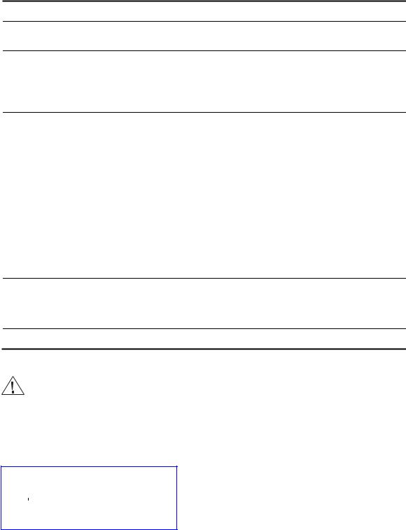
CAUTION: Rack Mount Safety Instructions (UL)
When installing the chassis in a rack, be sure to implement the following Safety instructions recommended by Underwriters Laboratories:
•Elevated Operating Ambient - If installed in a closed or multi-unit rack assembly, the operating ambient temperature of the rack environment may be greater than room ambient. Therefore, consideration should be given to installing the equipment in an environment compatible with the maximum ambient temperature (Tma) specified by the manufacturer.
•Reduced Air Flow - Installation of the equipment in a rack should be such that the amount of air flow required for safe operation on the equipment is not compromised.
•Mechanical Loading - Mounting of the equipment in the rack should be such that a hazardous condition is not achieved due to uneven mechanical loading.
•Circuit Overloading - Consideration should be given to the connection of the equipment to the supply circuit and the effect that overloading of the circuits might have on overcurrent protection and supply wiring. Appropriate consideration of equipment nameplate ratings should be used when addressing this concern.
•Reliable Earthing - Reliable earthing of rack-mounted equipment should be maintained. Particular attention should be given to supply connections other than direct connections to the branch circuit (e.g., use of power strips.)
Installing the V7111 24-PORT in a 19-inch Rack
The V7111 24-PORT is installed into a standard 19-inch rack by the addition of two short (equal-length) supplied brackets. The V7111 24-PORT with brackets for rack installation is shown in Figure 11.
To install the V7111 24-PORT in a 19-inch rack, follow these 7 steps:
1Remove the two screws on one side of the device nearest the front panel.
2Insert the peg on one of the brackets into the third air vent down on the column of air vents nearest the front panel.
3Swivel the bracket until the holes in the bracket line up with the two empty screw holes on the device.
4Use the screws found in the devices’ package to attach the bracket to the side of the device.
5Repeat Steps 1 to 4 to attach the second bracket to the other side of the device.
6Position the device in the rack and line up the bracket holes with the rack frame holes.
20 |
3Com VCX V7111 Analog Gateway Installation Guide |
7Use four standard rack screws to attach the device to the rack. These screws are not provided with the device.
Figure 11 V7111 24-PORT with Brackets for Rack Installation
Cabling the V7111 24-PORT
Figure 12 illustrates the rear panel of the V7111 24-PORT. For descriptions of the V7111 24PORT rear panel components, see Table 6.
Cable your V7111 24-PORT according to each section of Table 7.
Figure 12 V7111 24-PORT (FXS) Rear Panel Connectors
1 2 3 4 5 6
Table 6 |
V7111 24-PORT Rear Panel Component Descriptions |
|
||||||||
|
|
|
|
|
|
|
|
|
|
|
|
Item # |
Label |
Component Description |
|
||||||
|
|
|
|
|
|
|
|
|
|
|
1 |
|
|
|
|
|
|
|
Protective earthing screw (mandatory for all installations). |
|
|
|
|
|
|
|
|
|
|
|||
|
|
|
|
|
|
|
|
|||
|
|
|
|
|
|
|
|
|||
|
|
|
|
|
||||||
2 |
100-250 V~ |
AC power supply socket. |
|
|||||||
50 - 60 Hz 2A |
|
|||||||||
|
|
|
|
|||||||
|
|
|
|
|
||||||
3 |
ANALOG LINES 1 –24 |
50-pin Telco for 1 to 24 analog lines. |
|
|||||||
|
|
|
|
|
||||||
4 |
Data Cntrl Ready |
LED indicators (described in Table 11). |
|
|||||||
|
|
|
|
|
||||||
5 |
RS-232 |
9 pin RS-232 status port. |
|
|||||||
|
|
|
|
|
||||||
6 |
Eth 1 Eth 2 |
Dual 10/100 Base-TX Ethernet connections. |
|
|||||||
|
|
|||||||||
3Com VCX V7111 Analog Gateway Installation Guide |
21 |
|||||||||
RJ-45 Connector and Pinout
1 2 3 4 5 6 7 8 |
|
1 |
- Tx+ |
4, 5, 7, 8 |
|
|
2 |
- Tx- |
not |
|
|
3 |
- Rx+ |
|
|
|
connected |
||
|
|
6 |
- Rx- |
|
|
|
|
||
|
|
|
|
|
22 |
3Com VCX V7111 Analog Gateway Installation Guide |
Loading...