


 Loading...
3Com® Corporation
PathBuilder™ S24x, 26x, and 27x Switch
Installation Manual

Notice
© 1998 3Com Corporation 5400 Bayfront Plaza
®
Santa Clara, CA 95052-8145 (408) 326-5000
All rights reserved. Printed in U.S.A.
Portions reprinted with the permission of Motorola, Inc.
Restricted Rights Notification for U.S. Government Users
The software (including firmware) addressed in this manual is provided to the U.S. Government under agreement which grants the government the minimum “restricted rights” in the software, as defined in the Federal Acquisition Regulation (FAR) or the Defense Federal Acquisition Regulation Supplement (DFARS), whichever is applicable.
If the software is procured for use by the Department of Defense, the following legend applies:
Restricted Rights Legend
Use, duplication, or disclosure by the Government is subject to restrictions as set forth in subparagraph (c)(1)(ii) of the
Rights in Technical Data and Computer Software clause at DFARS 252.227-7013.
If the software is procured for use by any U.S. Government entity other than the Department of Defense, the following notice applies:
Notice
Notwithstanding any other lease or license agreement that may pertain to, or accompany the delivery of, this computer software, the rights of the Government regarding its use, reproduction, and disclosure are as set forth in FAR 52.227-19(C).
Unpublished - rights reserved under the copyright laws of the United States.

Notice (continued)
Proprietary Material
Information and software in this document are proprietary to 3Com (or its Suppliers) and without the express prior permission of an officer of 3Com, may not be copied, reproduced, disclosed to others, published, or used, in whole or in part, for any purpose other than that for which it is being made available. Use of software described in this document is subject to the terms and conditions of the 3Com Software License Agreement.
This document is for information purposes only and is subject to change without notice.
Part No. T0004, Rev. F
First Printing October 1998
Manual is current for Release 5.2M.

Contents
Chapter 1. About the PathBuilder S24x, 26x, and 27x switch
Applications .................................................................................................. |
1-3 |
Features and Protocols .................................................................................. |
1-7 |
Hardware Components ................................................................................. |
1-8 |
Enclosure .................................................................................................. |
1-11 |
Motherboard ............................................................................................. |
1-12 |
Back Panel ................................................................................................ |
1-16 |
TI Dual Port Digital PBX Interface Card ................................................. |
1-17 |
E1 Dual Port Digital PBX Interface Card ................................................ |
1-20 |
DSPM/SM Card ....................................................................................... |
1-23 |
DSPM Card with Analog E&M Interface ................................................ |
1-26 |
Setting Jumpers for DSPM Card with Analog E&M Interface ................ |
1-29 |
DSPM Card with FXS Analog Interface .................................................. |
1-32 |
DSPM Host Card with FXO Analog Interface ........................................ |
1-35 |
-48V Ringer/Power Supply Card and Enclosure ..................................... |
1-38 |
10BaseT Transceiver ................................................................................ |
1-41 |
Radio Frequency Interference Regulations .................................................. |
1-42 |
Telecommunications Regulations ................................................................. |
1-43 |
FCC and Telephone Company Procedures and Requirements ..................... |
1-45 |
FCC Information .......................................................................................... |
1-46 |
Chapter 2. Preparation and Unpacking |
|
|
|
Before Installing Your PathBuilder S24x, 26x, and 27x Switch .................. |
2-2 |
Unpacking ..................................................................................................... |
2-4 |
The PathBuilder S24x, 26x, and 27x Switch Rackmount Kit ...................... |
2-5 |
Installing the PathBuilder S24x, 26x, and 27x Switch in an Equipment Rack |
2-8 |
Chapter 3. PathBuilder S24x, 26x, and 27x Switch Hardware Installation |
|
|
|
Setting DIP Switches .................................................................................... |
3-3 |
Installing the DSU DIM ............................................................................... |
3-4 |
Configuring the PathBuilder S24x, 26x, and 27x Switch for DSU Operation |
3-7 |
DSU Input and Output Signaling ................................................................. |
3-8 |
Troubleshooting DSU Installation ................................................................ |
3-11 |
Installing DIMs ............................................................................................. |
3-12 |
Installing SIMMs .......................................................................................... |
3-14 |
Installing I/O Cards ...................................................................................... |
3-16 |
Installing a T1 or E1 Dual Port Digital PBX Interface Card ........................ |
3-17 |
Installing the T1/CSU Daughter Card ...................................................... |
3-19 |
Cabling the PathBuilder S24x, 26x, and 27x Switch ................................... |
3-22 |
Installing the Transceiver ............................................................................. |
3-23 |
Power-Up Diagnostics/Verification .............................................................. |
3-24 |
Installing Software Options .......................................................................... |
3-26 |
Full Mesh Cluster Cabling ............................................................................ |
3-27 |
v

Contents (continued)
Chapter 4. Maintenance
Removing/Replacing Top Cover .................................................................. |
4-3 |
Removing/Replacing Front Panel Cover ...................................................... |
4-5 |
Removing/Replacing Power Supply ............................................................. |
4-7 |
Removing/Replacing PathBuilder S24x, 26x, and 27x Switch Cards .......... |
4-9 |
Replacing PathBuilder S24x, 26x, and 27x Switch Motherboard ................ |
4-12 |
Removing/Replacing the Lithium Battery .................................................... |
4-14 |
Chapter 5. Channelized Data |
|
|
|
Application Example .................................................................................... |
5-2 |
Configuring Channelized Data ..................................................................... |
5-3 |
Configuring T1 and E1 Physical Ports ..................................................... |
5-5 |
T1 Port Parameters ................................................................................... |
5-7 |
E1 Port Parameters ................................................................................... |
5-13 |
Configuring Virtual Ports on the PathBuilder S24x, 26x, and 27x Switch |
5-18 |
Configuring Virtual Port Mapping Table ................................................. |
5-20 |
Appendix A. Cables |
|
|
|
Ethernet Cable Pinouts ................................................................................. |
A-6 |
Appendix B. PathBuilder S24x, 26x, and 27x Switch Specifications
Appendix C. PathBuilder S24x, 26x, and 27x Switch Error Codes
Appendix D. Technical Support
Index
vi

|
About This Manual |
Overview |
|
Introduction |
|
This manual describes features, hardware, specifications, and applications for the |
|
|
3Com PathBuilder S24x, 26x and 27x switch. |
Audience |
|
This manual is intended for operators of the 3Com PathBuilder S24x, 26x and 27x |
|
|
switch. |
How to Use This The following table describes the contents of this manual.
Manual
This Chapter... |
Describes: |
|
|
Chapter 1 |
PathBuilder S24x, 26x and 27x switch hardware and |
|
software features, and FCC and Telephone Company |
|
procedures and requirements. |
|
|
Chapter 2 |
Setting up a PathBuilder S24x, 26x and 27x switch, |
|
including site preparation, how to unpack the unit, and |
|
installation procedures. |
|
|
Chapter 3 |
Installing the hardware on the PathBuilder S24x, 26x |
|
and 27x switch, powerup and verification, and installa- |
|
tion of software options. |
|
|
Chapter 4 |
Maintaining the PathBuilder S24x, 26x and 27x switch |
|
including replacement of cards and motherboard. |
|
|
Chapter 5 |
Channelized Data option for the PathBuilder S24x, 26x |
|
and 27x switch. |
|
|
Appendix A |
Cable pinouts for Ethernet. |
|
|
Appendix B |
Product specifications. |
|
|
Appendix C |
Error Codes |
|
|
Appendix D |
Technical Support |
|
|
Special Notices The following notices emphasize certain information in the manual. Each serves a special purpose and is displayed in the format shown:

 Caution
Caution provides you with information that, if not followed, can result in damage to software, hardware, or data.

 Mise en Garde
Une mise en garde vous fournit des informations qui, si elles ne sont pas observées, peuvent se traduire par des dommages pour le logiciel, le matériel ou les données.
vii

About This Manual (continued)

 Vorsicht
Ein Vorsichtshinweis macht Sie darauf aufmerksam, daß Nic htbefolgung zu Software-, Hardwareoder Datenschäden führen kann.

 Warning
Warning is the most serious notice, indicating that you can be physically hurt.

 Avertissement
Un avertissement constitue le message le plus sérieux, indiquant que vous pouvez subir des blessures corporelles.

 Warnung
Eine Warnung ist der ernsthafteste Hinweis auf Körperverletzungsgefahr.
Trademarks |
PathBuilder is a trademark of 3Com Corporation. |
|
|
viii
|
Chapter 1 |
|
|
About the PathBuilder S24x, 26x, and 27x switch |
|
Overview |
|
|
|
|
|
What is the |
|
|
The PathBuilder S24x, 26x, and 27x switch is a multi-protocol LAN/WAN |
||
PathBuilder S24x, |
PathBuilder S200 series switch featuring a high-speed processor and coprocessor |
|
26x, and 27x |
coupled with 12 Mbytes of on-board memory (standard). Designed to address the |
|
switch? |
needs of large branch offices with higher throughput needs and regional |
|
|
concentration sites, the PathBuilder S24x, 26x, and 27x switch is available in rack- |
|
|
mount configurations. |
|
|
The PathBuilder S24x, 26x, and 27x switch’s high performance capabilities are |
|
|
uniquely matched to branch applications with high traffic requirements. |
|
|
As a regional concentrator, the PathBuilder S24x, 26x, and 27x switch accepts traffic |
|
|
from many branch locations into a single site and transfers the traffic to other devices |
|
|
at the regional or central site. |
|
|
The PathBuilder S24x, 26x, and 27x switch supports both Frame Relay and X.25. |
|
About the PathBuilder S24x, 26x, and 27x switch |
1-1 |
Meshed Cluster |
A unique feature of the PathBuilder S24x, 26x, and 27x switch is its ability to |
Application |
support full meshed cluster applications. This functionality provides host site |
Support |
resiliency, port count extension, and multiple LAN connectivity. |
|
Examples of how the features of the PathBuilder S24x, 26x, and 27x switch function |
|
in specific applications can be found the “Applications” section on page 1-3. |
|
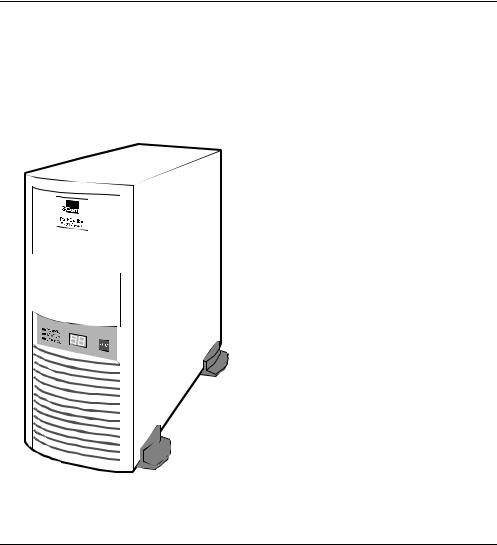
Figure 1-1 shows a PathBuilder S24x, 26x, and 27x switch. |
®
Figure 1-1. PathBuilder S24x, 26x, and 27x Switch
1-2 |
About the PathBuilder S24x, 26x, and 27x switch |
|
Applications |
Applications |
|
Introduction |
|
This section briefly describes several application examples for the PathBuilder S24x, |
|
|
26x, and 27x switch. |
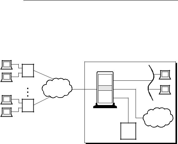
Performance |
|
Because of its high performance capabilities, the PathBuilder S24x, 26x, and 27x |
|
Branch Nodes |
switch can be employed in a variety of branch node applications. For example, the |
|
PathBuilder S24x, 26x, and 27x switch can support a mix of voice and data types, |
|
traditional legacy (SDLC, X.25, Bisync, Async, etc.), and LAN. Because of its high |
|
throughput, the PathBuilder S24x, 26x, and 27x switch can be used in situations |
|
where large file transfers, fast response time, and high numbers of users are the |
|
norm. Figure 1-2 is an example of a typical branch node application. |
|
Furthermore, the PathBuilder S24x, 26x, and 27x switch is designed to meet the |
|
needs of an expanding network. With its large RAM capacity and high-speed |
|
processor, the PathBuilder S24x, 26x, and 27x switch can easily adapt to a growing |
|
network with little or no additional hardware. |
|
|
|
|
|
|
|
|
|
|
|
|
|
|
|
|
|
|
|
|
|
|
|
|
|
|
|
|
|
|
|
|
|
|
|
|
|
|
|
|
|
|
|
|
|
|
|
|
PB S200 |
|
|
|
|
|
|
|
|
|
|
|
|
|
|
|
|
|
|
|
|
|
|
|
|
|
|
|
|
|
|
|
|
||||||
|
|
SNA |
|
|
Public |
|||||||||||||||||||||||
|
|
|
|
|
|
|
|
|
|
|
|
|
|
|
|
|
|
|
|
|
|
|
|
|
|
|
|
or Private |
|
|
|
|
|
|
|
|
|
|
|
|
|
|
|
|
|
|
|
|
|
|
|
|
|
|
|
|
|
|
|
|
|
|
|
|
|
|
|
|
|
|
|
|
|
|
|
|
|
|
|
|
|
|
|
|
|
Network |
|
|
|
|
|
|
|
|
|
|
|
|
|
|
|
|
|
|
|
|
|
|
|
|
|
|
|
||
|
|
|
|
|
|
|
|
|
|
|
|
|
|
|
|
|
|
|
|
|
|
|
|
|
|
|
|
|
|
|
|
|
|
|
|
|
|
|
|
|
|
|
|
|
|
|
|
|
|
|
|
|
|
|
|
|
|
|
|
|
|
|
|
|
|
|
|
|
|
|
|
|
|
|
|
|
|
|
|
|
|
|
|
|
|
|
|
|
|
|
|
|
|
|
|
|
|
|
|
|
|
|
|
|
|
|
|
|
|
|
|
|
|
|
|
|
|
|
|
|
|
|
|
|
|
|
|
|
|
|
|
|
|
|
|
|
|
|
|
|
|
|
|
|
|
|
|
|
|
|
|
|
|
|
|
|
|
|
|
|
|
|
|
|
|
|
|
|
|
|
|
|
|
|
|
|
|
|
|
|
|
|
|
|
|
|
|
|
|
|
|
|
|
|
|
|
|
|
|
|
|
|
|
|
|
|
|
|
|
|
|
|
|
|
|
|
|
|
|
|
|
|
|
|
|
|
|
|
|
|
|
|
|
|
|
|
|
|
|
|
|
|
|
|
|
|
|
|
|
|
|
|
|
|
|
|
|
|
|
|
|
|
|
|
|
|
|
|
|
|
|
|
|
|
|
|
|
|
|
|
|
|
|
|
|
|
|
|
|
|
|
|
|
|
|
|
|
|
|
|
|
|
|
|
|
|
|
|
|
|
|
|
|
|
|
|
|
|
|
|
|
|
|
|
|
|
|
|
|
|
|
|
|
|
|
|
|
|
|
|
|
|
|
|
|
|
|
Figure 1-2. Performance Branch Node Example
About the PathBuilder S24x, 26x, and 27x switch |
1-3 |
Applications
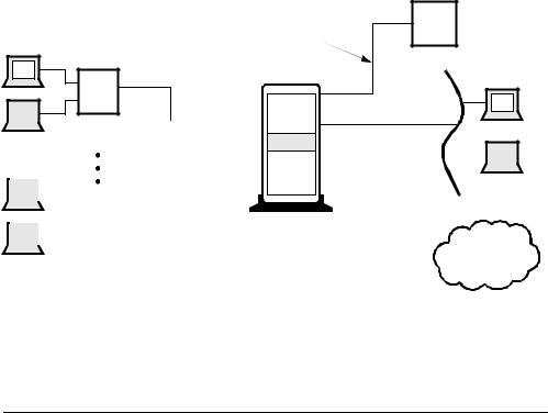
Regional |
In Figure 1-3, the public network (Frame Relay/X.25) is performing the branch |
Concentrator |
concentration function with the PathBuilder S24x, 26x, and 27x switch routing the |
|
traffic to the appropriate end point. In Figure 1-4, the PathBuilder S24x, 26x, and |
|
27x switch acts as the regional concentrators, receiving traffic from dozens and even |
|
thousands of remote sites, and concentrating the traffic before forwarding it to the |
|
correct location. In this case, the PathBuilder S24x, 26x, and 27x switch is the |
|
regional site. |
In both examples, the PathBuilder S24x, 26x, and 27x switch could be either a single node or a group of nodes networked together as a cluster. The PathBuilder S24x, 26x, and 27x switch’s cluster feature is described below.
|
Central Site |
|
Branch 1 |
PB S200 |
|
PB S200 |
||
|
Frame Relay |
|
|
or X.25 |
|
Branch XX |
(Single Node or Cluster) |
|
PBX |
||
PB S200 |
||
|
Host |
Figure 1-3. Regional Concentrator With Public Network Example
1-4 |
About the PathBuilder S24x, 26x, and 27x switch |
Applications
Central Site
High-Speed Link |
|
Branch 1 |
|
PB S200 |
|
|||
|
|
PB S200
|
|
|
|
|
|
|
|
|
|
|
|
|
|
|
|
|
|
|
|
|
|
|
|
|
|
|
|
|
|
|
|
|
|
|
|
|
|
|
|
|
|
|
|
|
|
|
|
|
|
|
|
|
|
|
|
|
|
|
|
|
|
|
|
|
|
|
|
|
|
|
|
|
|
|
|
|
|
|
|
|
|
|
|
|
|
|
|
|
|
|
|
|
|
|
|
|
|
|
|
|
|
|
|
|
|
|
|
|
|
|
|
|
|
|
|
|
|
|
|
|
|
(Single Node or Cluster) |
|
|
|
|
|
||||||||||
|
|
|
|
|
|
|
|
|
|
|
|
|
|
|
|
|
|
|
|
|
|
|
|
|
|
Branch XX |
|
|
|
|
|
|
|
|
|
|
|
|
|
PBX |
|||||
|
|
|
|
|
|
|
|
|
|
|
|
|
|
|
|
|||||||
|
|
|
|
PB S200 |
|
|
|
|
|
|
|
|
|
|
|
|
|
|||||
|
|
|
|
|
|
|
|
|
|
|
|
|
|
|
|
|
|
|
|
|||
|
|
|
|
|
|
|
|
|
|
|
|
|
|
|
|
|
|
|
|
|||
|
|
|
|
|
|
|
|
|
|
|
|
|
|
|
Host |
|
|
|
||||
|
|
|
|
|
|
|
|
|
|
|
|
|
|
|
|
|
|
|
|
|
|
|
Figure 1-4. Regional Concentrator Example
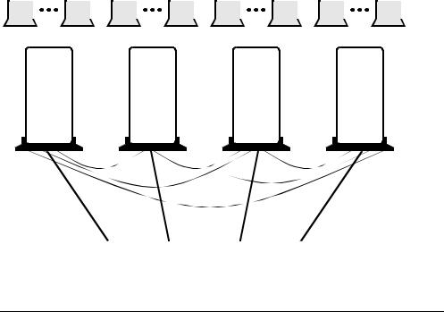
Cluster Application An important new feature available with the PathBuilder S24x, 26x, and 27x switch is its use in a cluster. This allows as many as four PathBuilder S24x, 26x, and 27x switches to act a single unit for the purposes of connectivity. Though configured and managed as individual nodes, when the PathBuilder S24x, 26x, and 27x switches are clustered together, devices attached to access ports on one node can have calls routed out the network port of one of the other nodes.
The three high-speed ports on the PathBuilder S24x, 26x, and 27x switch motherboard provide networking channels between the nodes to pass traffic from network ports to access ports. The PathBuilder S24x, 26x, and 27x switch cluster allows for high port count and throughput primarily in support of the regional concentrator applications.
The example in Figure 1-5 is a full mesh cluster which means that any access link can reach any host connection. If a PathBuilder S24x, 26x, and 27x switch node within the cluster fails, only those links and host connections directly connected to that node go down. Placement of host equipment, and use of redundant host equipment can minimize the impact of any individual node failure. Furthermore, Link Back Up features in the remotes can limit the degree of remote isolation if part of the PathBuilder S24x, 26x, and 27x switch cluster fails.
About the PathBuilder S24x, 26x, and 27x switch |
1-5 |
Applications
|
16 Access Ports |
|
|
16 Access Ports |
|
|
16 Access Ports |
|
|
16 Access Ports |
||||||||||||||||||||||||||||||||||||
|
|
|
|
|
|
|
|
|
|
|
|
|
|
|
|
|
|
|
|
|
|
|
|
|
|
|
|
|
|
|
|
|
|
|
|
|
|
|
|
|
|
|
|
|
|
|
|
|
|
|
|
|
|
|
|
|
|
|
|
|
|
|
|
|
|
|
|
|
|
|
|
|
|
|
|
|
|
|
|
|
|
|
|
|
|
|
|
|
|
|
|
|
|
|
|
|
|
|
|
|
|
|
|
|
|
|
|
|
|
|
|
|
|
|
|
|
|
|
|
|
|
|
|
|
|
|
|
|
|
|
|
|
|
|
|
|
|
|
|
|
|
|
|
|
|
|
|
|
|
|
|
|
|
|
|
|
|
|
|
|
|
|
|
|
|
|
|
|
|
|
|
|
|
|
|
|
|
|
|
|
|
|
|
|
|
|
|
|
|
|
|
|
|
|
|
|
|
|
|
|
|
|
|
|
|
|
|
|
|
|
|
|
|
|
|
|
|
|
|
|
|
|
|
|
|
|
|
|
|
|
|
|
|
|
|
|
|
|
PB S200 |
|
|
|
|
|
|
PB S200 |
|
|
|
|
|
|
PB S200 |
|
|
|
|
|
|
PB S200 |
|
||||||||
|
|
|
|
|
|
|
|
|
|
|
|
|
|
|
|
|
|
|
|
|
|
|
|
|
|
|
|
|
|
|
|
|
|
|
|
|
|
|
|
|
|
|
|
|
|
|
|
|
|
|
|
|
|
|
|
|
|
|
|
|
|
|
|
|
|
|
|
|
|
|
|
|
|
|
|
|
|
|
|
|
|
|
|
|
|
|
|
|
|
|
|
|
|
|
|
|
|
|
|
|
|
|
|
|
|
|
|
|
|
|
|
|
|
|
|
|
|
|
|
|
|
|
|
|
|
|
|
|
|
|
|
|
|
|
|
|
|
|
|
|
|
|
|
|
|
|
|
|
|
|
|
|
|
|
|
|
|
|
|
|
|
|
|
|
|
|
|
|
|
|
|
|
|
|
High-Speed Network Links to other Sites or Backbone LAN Connectors
Figure 1-5. PathBuilder S24x, 26x, and 27x Switch Cluster Example
1-6 |
About the PathBuilder S24x, 26x, and 27x switch |
|
|
Features and Protocols |
Features and Protocols |
||
Description |
|
|
For a complete listing of the features and protocols supported by your PathBuilder |
||
|
|
S24x, 26x, and 27x switch, refer to the Software Release Notice that came with the |
|
|
operating software. |
|
|
|
About the PathBuilder S24x, 26x, and 27x switch |
1-7 |

Hardware Components
Hardware Components
PathBuilder S24x, 26x, and 27x Switch Hardware Configuration
The PathBuilder S24x, 26x, and 27x switch comes in a rack-mountable configuration.
The switch contains a motherboard/CPU board, a built-in power supply, and an ISA bus for up to eight additional interface cards. The PathBuilder S24x, 26x, and 27x switch has three available serial ports, an Ethernet port, and a CTP port, FLASH memory, and battery-powered configuration backup. It is easily expanded by adding option cards to the industry standard ISA bus.
Figure 1-6 shows a rack-mountable PathBuilder S24x, 26x, and 27x switch.
SSN |
Status |
Numeric |
Label |
LEDs |
LED |
|
|
PO WER |
|
|
S TAT U S |
|
|
SE R VI CE |
|
|
® |
|
|
PathBuilder |
|
|
S200 Series |
|
|
RESET |
Front View |
|
Reset |
|
|
|
|
|
Button |
|
Product ID |
AUI Port 4 |
Power |
|
|
Label |
(Ethernet Routing) |
Supply |
|
|
|
|
Product |
|
|
|
|
ID Label |
|
Rear View |
|
Serial/Network |
115/230 VAC |
|
Expansion |
|
|||
I/O Ports 1, 2, 3, 6 |
Voltage |
|||
Card Ports |
||||
|
|
Select |
||
Slots 1 through 8 |
|
|
||
|
|
Switch |
||
|
|
|
||
Figure 1-6. PathBuilder S24x, 26x, and 27x Switch |
||||
Optional -48V
Power Supply
1-8 |
About the PathBuilder S24x, 26x, and 27x switch |

Hardware Components
Hardware |
This table lists and briefly describes the hardware components that make up the |
|
Components |
PathBuilder S24x, 26x, and 27x switch. More detailed descriptions of these |
|
|
components follow. |
|
|
|
|
|
Component |
Description |
|
|
|
|
Enclosure |
A rack-mount unit that contains all the PathBuilder S24x, |
|
|
26x, and 27x switch processor cards. |
|
|
|
|
Back Panel |
Contains power outlets, power switch, communication ports, |
|
|
and slots for I/O cards. |
|
|
|
|
Motherboard |
Contains five data ports: |
|
|
• Ports 1 and 2 are DIM ports |
|
|
• Port 3 is a high-speed/V.36 DTE port |
|
|
• Port 4 is the Ethernet AUI port |
|
|
(see below for limitations) |
|
|
• Port 6 is reserved for the control terminal port |
|
|
Contains eight full-size expansion slots. |
|
|
|
|
Integral DSU DIM |
An option used in installations requiring connection to a |
|
(Optional) |
DDS interface conforming to AT&T 62310 or |
|
|
ANSI T1E1.4/91-006, and running at 56 kbps. |
|
|
|
|
10Base2 |
Lets you accommodate different network configurations |
|
Transceiver for AUI |
through the user-selectable Signal Quality Error (SQE) |
|
ports (optional) |
function. |
|
|
|
|
T1 Dual Port |
The T1 dual port digital PBX interface card supports digital |
|
Digital PBX |
voice communications, providing integrated network access. |
|
Interface Card |
The T1 digital interfaces are used for both voice and data |
|
PathBuilder S24x, |
traffic. |
|
26x, and 27x |
|
|
|
|
|
E1 Dual Port |
The E1 dual port digital PBX interface card supports digital |
|
Digital PBX |
voice communications, providing integrated network access |
|
Interface Card |
(see Figure 1-12). |
|
|
The E1 interface card is used to support both voice and data |
|
|
traffic. |
|
|
|
|
DSPM/SM |
The DSPM/SM card, used at nodes with digital PBX |
|
|
interfaces, compresses four digital voice channels. It has no |
|
|
external I/O capabilities. |
|
|
|
|
DSPM with FXS |
The analog DSPM/FXS card allows the PathBuilder S24x |
|
Analog Interface |
switch to support up to two voice/fax channels per card. Each |
|
|
DSPM/FXS card occupies one ISA slot in the PathBuilder |
|
|
S24x switch. |
|
|
|
|
DSPM with FXO |
The analog FXO daughtercard (when mounted on the |
|
Analog Interface |
DSPM/HC) allows the PathBuilder S244 and S254 switch to |
|
|
support one voice/fax channel per card. Each DSPM/HX |
|
|
with FXO daughtercard combination occupies one ISA slot |
|
|
in the PathBuilder S244 and S254 switch. |
|
|
|
About the PathBuilder S24x, 26x, and 27x switch |
1-9 |

Hardware Components
Component |
Description (continued) |
|
|
DSPM with E&M |
The PathBuilder S26x switch Analog DSPM/E&M card |
Interface |
allows the PathBuilder S26x switch to support up to two (2) |
|
voice/fax channels per card. Each E&M card occupies one |
|
ISA slot in the PathBuilder S26x switch. The PathBuilder |
|
S26x switch E&M card supports both twoand four-wire |
|
interfaces. |
|
|
Ethernet Port 4
Limitations
Consider these limitations when using the Ethernet Port 4:
• The port does not support Bridging (refer to the Bridging Option,
Part No. T0008-16). When configuring this port, you are not prompted for the bridge link number.
•The port does not support SLAC.
•When configuring the Ethernet Port 4, you are not prompted for the connector type. Ethernet Port 4 only supports AUI.
1-10 |
About the PathBuilder S24x, 26x, and 27x switch |

|
Hardware Components |
Enclosure |
|
Introduction |
|
This section provides detailed information about the parts of the PathBuilder S24x, |
|
|
26x, and 27x switch enclosure. |
Front Panel |
|
The PathBuilder S24x, 26x, and 27x switch front panel (see Figure 1-6) has: |
|
|
• Three status LEDs |
|
• A 2-character numeric LED display |
|
• A RESET switch |
Status LEDs |
|
The three status LEDs are: |
|
|
• Power (green) — When on, indicates that power is on and all DC voltages are |
|
within specifications. |
|
• Status (green) — When on, indicates that the PathBuilder S24x, 26x, and 27x |
|
switch node is executing either a power-up diagnostic or a software download. |
|
This LED is normally off. |
|
• Service (yellow) — When on, indicates a hardware failure. This LED is |
|
normally off. |
Numeric LED |
|
The 2-character numeric LED display provides system diagnostic codes. When the |
|
Display |
Service LED is on, a 2-digit code on the numeric LED display corresponds to a |
|
certain event. |
Reset Switch |
|
The RESET switch resets the node. Pressing the RESET switch is the equivalent of a |
|
|
power-up operation which clears all existing calls and brings down all links. |
Power Supply |
|
The power supply is mounted at the top rear of the chassis. The AC switchable power |
|
|
supply can operate at a nominal 110 or a nominal 230 Volts. For information about |
|
maintaining and replacing the power supply, refer to Chapter 4, Maintenance. |

 Note
Note
For this unit, the -48VDC Power Option is also available.
About the PathBuilder S24x, 26x, and 27x switch |
1-11 |
Hardware Components
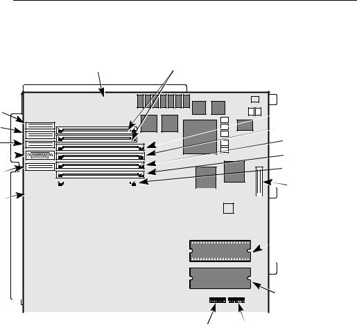
Motherboard
Parts of the |
This section describes some of the components that make up the PathBuilder S24x, |
||||||||||
Motherboard |
26x, and 27x switch motherboard. In addition, this section describes some of the |
||||||||||
|
daughtercards that can be found on the motherboard, shown in Figure 1-7. |
||||||||||
|
|
|
|
Power Supply |
DRAM SIMM |
||||||
|
|
|
|
Ringer Status |
Slots 1 and 2 |
||||||
|
|
|
|
|
|
|
|
|
|
|
|
|
|
|
|
|
|
|
|
|
|
|
|
|
|
|
|
|
|
|
|
|
|
|
|
|
|
|
|
|
|
|
|
|
|
|
|
Port 1 |
Flash SIMM Slot |
|
Port 2 |
Optional Flash |
|
SIMM Slot |
||
Port 3 |
CMEM SIMM Slot |
|
Etherspan |
Data Compression |
|
SIMM Slot |
||
AUI |
||
Global DRAM |
||
Port 4 |
||
SIMM Slot |
|
Port 6 |
|
|
|
|
|
|
|
|
|
|
|
|
|
|
|
|
|
|
|
|
|
|
|
|
|
|
|
|
LED Connector |
|||||
|
|
|
|
|
|
|
|
|
|
|
|
|
|
|
|
|
|
|
|
|
|
|
|
|
|
|
|
|
|||||||
|
|
|
|
|
|
|
|
|
|
|
|
|
|
|
|
|
|
|
|
|
|
|
|
|
|
|
|
|
|
|
|
|
|||
|
|
|
|
|
|
|
|
|
|
|
|
|
|
|
|
|
|
|
|
|
|
|
|
|
|
|
|
|
|
|
|
|
|||
|
|
|
|
|
|
|
|
|
|
|
|
|
|
|
|
|
|
|
|
|
|
|
|
|
|
|
|
|
|
|
|
|
|||
|
|
|
|
|
|
|
|
|
|
|
|
|
|
|
|
|
|
|
|
|
|
|
|
|
|
|
|
|
|||||||
|
|
|
|
|
|
|
|
1 |
|
|
|
|
|
|
|
|
|
|
|
|
|
|
|
|
|
|
|
|
|
|
|
|
|||
|
|
|
|
|
|
|
|
|
|
|
|
|
|
|
|
|
|
|
|
|
|
|
|
|
|
|
|
|
|
|
|
|
|
|
|
|
|
|
|
|
|
|
|
|
|
|
2 |
|
|
|
|
|
|
|
|
|
|
|
|
|
|
|
|
|
|
|
|
|
|
|
|
|
|
|
|
|
|
|
|
|
|
|
|
|
|
|
|
|
|
|
|
|
|
|
|
|
|
|
|
|
|
|
|
|
|
|
|
|
|
|
|
|
|
|
|
|
|
|
3 |
|
|
|
|
|
|
|
|
|
|
|
|
|
|
|
|
|
|
|
|
|
|
|
|
|
|
|
|
|
|
|
|
|
|
|
|
|
|
|
|
|
|
|
|
|
|
|
|
|
|
|
|
|
|
|
|
|
|
||
|
|
|
|
|
|
|
|
|
|
|
|
|
|
|
|
|
|
|
|
|
|
|
|
|
|
|
|
|
|
|
Port 1 |
|
|
||
|
|
|
|
|
|
|
|
|
|
|
4 |
|
|
|
|
|
|
|
|
|
|
|
|
|
|
|
|
|
|
|
|
|
|
||
|
|
|
|
|
|
|
|
|
|
|
|
|
|
|
|
|
|
|
|
|
|
|
|
|
|
|
|
|
|
|
|||||
|
|
|
|
|
|
|
|
|
|
|
|
|
|
|
|
|
|
|
|
|
|
|
|
|
|
|
|
|
|
|
|
|
|
|
|
|
|
|
|
|
|
|
|
|
|
|
|
|
|
|
|
|
|
|
|
|
|
|
|
|
|
|
|
|
|
|
|
|
|
||
|
|
|
|
|
|
|
|
5 |
|
|
|
|
|
|
|
|
|
|
|
|
|
|
|
|
|
|
|
|
|
|
|
DIMs |
|||
|
|
|
|
|
|
|
|
|
|
|
|
|
|
|
|
|
|
|
|
|
|
|
|
|
|
|
|
|
|
|
|||||
|
|
|
|
|
|
|
|
|
|
|
|
|
|
|
|
|
|
|
|
|
|
|
|||||||||||||
|
|
|
|
|
|
|
|
|
|
|
|
|
|
|
|
|
|
|
|
|
|
|
|
|
|
|
|
|
|
|
|
|
|
||
|
|
|
|
|
|
|
|
|
|
|
6 |
|
|
|
|
|
|
|
|
|
|
|
|
|
|
|
|
|
|
|
|
|
|
|
|
|
|
|
|
|
|
|
|
|
|
|
|
|
|
|
|
|
|
|
|
|
|
|
|
|
|
|
|
|
|
|
|
|
|
|
|
|
|
|
|
|
|
|
|
|
|
|
|
|
|
|
|
|
|
|
|
|
|
|
|
|
|
|
|
|
|
|
|
|
|
|
|
|
|
|
|
|
|
|
|
|
|
|
|
|
|
|
|
|
|
|
|
|
|
|
|
|
|
|
|
|
|
|
|
|
|
|
|
|
|
|
|
|
|
|
|
7 |
|
|
|
|
|
|
|
|
|
|
|
|
|
|
|
|
|
|
|
|
Port 2 |
|
|
||||
|
|
|
|
|
|
|
|
|
|
|
|
|
|
|
|
|
|
|
|
|
|
|
|
|
|
|
|
|
|
|
|
|
|||
|
|
|
|
|
|
|
|
|
|
|
|
|
|
|
|
|
|
|
|
|
|
|
|
|
|
|
|
|
|
|
|
|
|||
|
|
|
|
|
|
|
|
|
|
|
|
|
|
|
|
|
|
|
|
|
|
|
|
|
|
|
|
|
|
|
|
||||
|
|
|
|
|
|
|
|
|
|
|
8 |
|
|
|
|
|
|
|
|
|
|
|
|
|
|
|
|
|
|
|
|
|
|
||
|
|
|
|
|
|
|
|
|
|
|
|
|
|
|
|
|
|
|
|
|
|
|
|
|
|
|
|
|
|
|
|
|
|
|
|
|
|
|
|
|
|
|
|
|
|
|
|
|
|
|
|
|
|
|
|
|
|
|
|
|
|
|
|
|
|
|
|
|
|
||
|
|
|
|
|
|
|
|
|
|
|
|
|
|
|
|
|
|
|
|
|
|
|
|
|
|
|
|
|
|
|
|
|
|
||
|
|
|
|
|
|
|
|
|
|
|
|
|
|
|
|
|
|
|
|
|
|
|
|
|
|
|
|
|
|
|
|
|
|
|
|
|
|
|
|
|
|
|
|
|
|
|
|
|
|
|
|
|
|
Switch 2 Switch 1 |
|||||||||||||||||
|
|
Figure 1-7. Motherboard |
|
|
|
|
|
|
|
|
|
|
|
|
|
|
|
|
|
|
|
|
|
|
|
||||||||||
RAM |
|
|
|
|
|
|
|
|
|
|
|
|
|
|
|
|
|
|
|
|
|
|
|
|
|
|
|
|
|
|
|
|
|
|
|
|
The PathBuilder S24x, 26x, and 27x switch comes standard with 16 Mbytes of local |
||||||||||||||||||||||||||||||||||
|
|
DRAM for image execution and 8 Mbytes of global memory for buffer storage. |
|||||||||||||||||||||||||||||||||
Ports |
|
|
|
|
|
|
|
|
|
|
|
|
|
|
|
|
|
|
|
|
|
|
|
|
|
|
|
|
|
|
|
|
|
|
|
|
There are four serial data port DB-25 connectors for network or access functions |
||||||||||||||||||||||||||||||||||
|
|
(2.048 Mbps): |
|
|
|
|
|
|
|
|
|
|
|
|
|
|
|
|
|
|
|
|
|
|
|
||||||||||
•Ports 1 and 2 (DB 25) are Data Interface Module (DIM) ports
•Port 3 (DB 25) is a V.36 DTE port
•Port 4 (DB 15) is an Ethernet AUI port
•Port 6 (DB25) is the Control Terminal Port (EIA232)
1-12 |
About the PathBuilder S24x, 26x, and 27x switch |
Hardware Components
FLASH SIMM |
The FLASH Single In-line Memory Module (SIMM) holds a compressed image of |
|
the operating software. This module is electrically erasable and reprogrammable. |
|
An optional FLASH SIMM can be installed for backup. These modules are installed |
|
in one of the SIMM slots (1 or 2). Figure 1-8 shows the SIMM. |
|
|
|
Figure 1-8. FLASH SIMM |
||
|
|
|
|
|
Note |
|
|
|
|
|
|
|
|
|
|
|
|
|
|
|
|
|
The chips on your SIMM may vary from the one shown inFigure 1-8. |
CMEM SIMM |
|
|
|
||
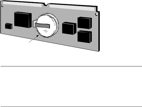
The Configuration Memory Module (CMEM) SIMM has 512 Kbytes of memory and |
|||||
|
|
|
provides the real time clock function. The CMEM is backed up by a lithium battery |
||
|
|
|
in case of a power disruption. |
||
|
|
|
Each PathBuilder S24x, 26x, and 27x switch has a Software Serial Number (SSN) |
||
|
|
|
burned into a PROM located on the CMEM card. This SSN is used to verify the |
||
|
|
|
software options that are enabled for that node. It is on the CMEM SIMM card for |
||
|
|
|
easy removal and replacement in case of a motherboard failure. |
||
|
|
|
The CMEM is installed in the SIMM slot (see Figure 1-7 for slot location). |
||
|
|
|
Figure 1-9 shows the CMEM. |
||
|
|
|
|
Warning |
|
|
|
|
Only qualified service personnel should perform the procedure described in this |
||
|
|
|
|||
|
|
|
section. If the battery is installed incorrectly, it could explode after the PathBuilder |
||
|
|
|
S200 series switch product is powered up, damaging the unit. |
||
|
|
|
|
Avertissement |
|
|
|
|
Seules des personnes qualifiées peuvent mettre en pratique les procédures décrites |
||
|
|
|
|||
|
|
|
dans cette section. Si la batterie n’est pas correctement installée, elle risque |
||
|
|
|
d’exploser après la mise en marche du produit PathBuilder S200 series switch et |
||
|
|
|
d’endommager l’unité. |
||
|
|
|
|
Warnung |
|
|
|
|
Die in diesem Abschnitt aufgeführten Vorgänge sollten ausschließlich von |
||
|
|
|
|||
|
|
|
qualifiziertem Servicepersonal durchgeführt werden. Wenn die Batterie |
||
|
|
|
unsachgemäß installiert wird, kann sie nach dem Einschalten des PathBuilder S200 |
||
|
|
|
series switch-Produkts explodieren |
||
About the PathBuilder S24x, 26x, and 27x switch |
1-13 |
Hardware Components
Lithium Battery
Figure 1-9. CMEM SIMM
Expansion Port The PathBuilder S24x, 26x, and 27x switch motherboard has eight full-size
I/O Slots expansion card slots (see Figure 1-6). Expansion I/O cards have I/O connectors that extend through the rear panel.
Port numbers for the ports on the I/O cards have a fixed relationship to the chassis expansion slot number. Six port numbers are reserved for each slot. If a slot contains an I/O card that does not support the full port count reserved for that slot, or the slot is empty, the extra port numbers remain unused.
Slot Number and This table shows the port numbers associated with each card type.
Port Numbers
|
Slot Number |
Port Number |
Associated Card |
|
|
|
|
|
Motherboard I/O |
1-6 |
Motherboard |
|
|
|
|
|
1 |
7-12 |
Voice cards (E & M, FXS, |
|
|
|
Server Module, T1, E1). |
|
2 |
13-18 |
|
|
The T1/E1 is restricted to |
||
|
|
|
|
|
3 |
19-24 |
|
|
Slot 8. |
||
|
|
|
|
|
4 |
25-30 |
|
|
|
|
|
|
5 |
31-36 |
|
|
|
|
|
|
6 |
37-42 |
|
|
|
|
|
|
7 |
43-48 |
|
|
|
|
|
|
8 |
49-54 |
|
Description of |
|
|
|
|
|
|
|
Ports 1 through 3 are connected to the motherboard with ribbon cables. Ports 1 and 2 |
|||
Serial/Network |
are DIM ports and are functional only if a DIM is present. Port 3 is a dedicated V.36 |
||
Ports |
DTE port. |
|
|
Ports 1, 2, 3, and 6 on the rear panel of the chassis are DB-25 female connectors. Port 4, (the Ethernet AUI port) uses a DB-15 connector. Ports 1 and 2 may require adapters, depending on the DIM used. An adapter cable is available for Port 3.
1-14 |
About the PathBuilder S24x, 26x, and 27x switch |

Hardware Components
How Ports Are The following table describes how the ports are used.
Used
Port Number |
Use |
|
|
1, 2, and 3 |
Recommended for network port connection or cluster |
|
connectivity. Ports 1 and 2 have variable interfaces, depending |
|
on the DIMs. |
|
|
4 |
Ethernet AUI port for routing applications. |
|
|
6 |
Control Terminal Port (CTP). When operating as an |
|
asynchronous interface, it can support data rates up to 115.2 |
|
kbps. Default CTP configuration parameters are 9600 baud, |
|
8-bit characters, 1 stop bit, no parity. This is an EIA 232-D |
|
DCE port using a DB-25 connector. |
|
|
DIMs without a Cable Adapter
DIMs with a Cable Adapter
Ports 1 and 2 support a DSU DIM without the use of cable adapters.
If cable adapters are used, Ports 1 and 2 can support the following DIMs:
•High Speed (V.36)
•V.35
•V.11/ISO-4903
Each DIM port can be configured independently of the other port. For example, you can install: two V.35 DIMs; one V.35 DIM and one V.11 DIM; or two V.11 DIMs.
The cable adapter pinouts are described in Appendix A, Cables.
About the PathBuilder S24x, 26x, and 27x switch |
1-15 |
Hardware Components
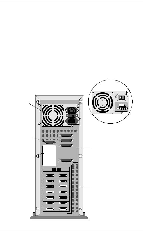
Back Panel
Back Panel
Components
The components of the back panel are:
•Serial/Network I/O Ports. Ports 1, 2, 3, and 6 are DB-25 connectors. Port 4 is a DB 15 connector.
•AC Power Supply. The rear of the Power Supply has two (male and female) power source connectors (one is for connection to an AC source and the other is an AC outlet) along with a selectable 115 VAC or 230 VAC switch. For most international usage, the switch must be set for 230 VAC.
•DC Power Supply. The unit can be shipped with the -48VDC Power Option. The terminal block of the -48VDC has 5 screws. The two outermost screws are for attachment. The negative wire terminal is second from the left; the positive wire terminal is in the middle; the ground is second from the right.
•Expansion Card Ports. The expansion card ports differ depending on what card is installed in that slot.
Figure 1-10 shows the PathBuilder S24x, 26x, and 27x switch back panel.
Optional -48V
Power Supply
Power |
|
Supply |
|
|
115/230 VAC |
|
Voltage Select |
AUI Port 4 |
Switch |
|
|
(Ethernet Routing) |
|
|
Serial/Network |
|
I/O Ports 1,2, 3, 6 |
Product |
|
ID Label |
|
|
Expansion |
|
Card Ports |
|
Slots 1 through 8 |
Figure 1-10. PathBuilder S24x, 26x, and 27x Switch Back Panel
1-16 |
About the PathBuilder S24x, 26x, and 27x switch |
|
Hardware Components |
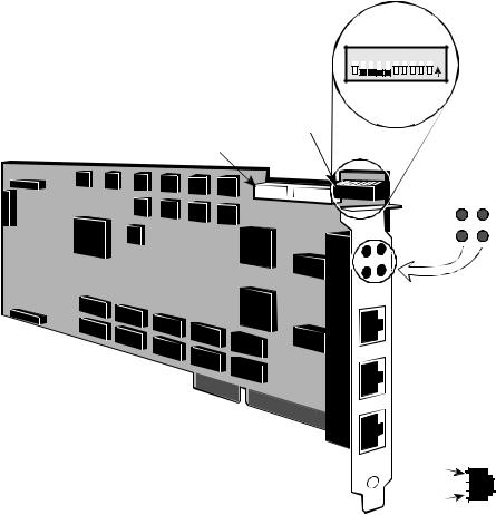
TI Dual Port Digital PBX Interface Card |
|
Introduction |
|
The T1 dual port digital PBX interface card supports digital voice communications, |
|
|
providing integrated network access. The T1 interface card is installed primarily in |
|
North America and Japan. A 2-megabyte T1 card is required for passing data and |
|
voice traffic. |
109 8 7 6 5 4 3 2 1 N 


 O
O
SW1 DIP Switch Bank
MVIP Bus Interface Connector
Port 49 LED |
Port 50 LED |
Run LED |
SysFail LED |
|
|
Port 49 Interface |
|||
|
|
Port 50 Interface |
|||
|
ISA Bus Interface |
Serial Diagnostic Port (Not Supported) |
|||
|
|
||||
|
|
Pin 8 |
|
|
|
|
|
|
|
|
|
|
|
Pin 1 |
|
|
|
|
|
|
|
|
|
|
Figure 1-11. T1 Dual Port Digital PBX Interface Card |
|
|
||
Description |
|
|
|
|
|
Each T1 dual port digital PBX interface card uses an Industry Standard Architecture |
|||||
|
(ISA) bus interface and a Multi-Vendor Integration Protocol (MVIP) bus interface. |
||||
|
The MVIP bus interface provides multiplexed digital access within the PathBuilder |
||||
|
S24x, 26x, and 27x switch chassis. |
|
|
|
|
Function |
|
|
|
|
|
T1 dual port digital PBX interface cards provide the digital interfaces for |
|||||
|
connections to a PBX. The T1 dual port digital PBX interface cards bring PCM voice |
||||
|
and channel signaling into the node. The PCM voice data and voice signaling is |
||||
|
routed to a DSPM/SM card over the MVIP bus for compression and transmission to |
||||
|
the remote end. |
|
|
|
|
About the PathBuilder S24x, 26x, and 27x switch |
1-17 |

Hardware Components
Slot Restriction |
The T1 dual port digital PBX interface card occupies slot 8 in the PathBuilder S24x, |
|
26x, and 27x switch chassis. |
DIP Switch |
|
The T1 dual port digital PBX interface card contains a single DIP switch bank (SW1) |
|
Location |
used to assign the card’s I/O base address. |
DIP Switch |
|
Set the DIP switches on the T1 dual port digital PBX interface card as shown in |
|
Settings |
Figure 1-11. |
T1/CSU Daughter |
|
The T1/CSU Daughtercard provides a 1.544 MHz point-to-point interface for North |
|
Card |
American service that conforms to AT&T 62411/62421 standard. The card is FCC |
|
Part 68 Registered and uses eternal clocking derived from the telephone network. |
|
One or two T1/CSU Daughter Cards can be installed onto the T1 Dual Port card. The |
|
top card supports port 49 and the bottom supports port 50. |
|
For instructions for installing the T1/CSU card, refer to “Installing the T1/CSU |
|
Daughter Card” section in Chapter 3. |
Required Cables These cables ship with the T1 dual port digital PBX interface card and are required to cable the T1 dual port digital PBX interface card to the DSPM/SM cards in the node.
Cable Description |
Function |
|
|
One 4-position 40-pin |
Connects up to 3 DSPM/SM cards to interconnect |
MVIP ribbon cable |
digital voice traffic between individual cards in the |
|
same PathBuilder S24x, 26x, and 27x switch node. |
|
|
One 8-position 40-pin |
Connects 4 or more DSPM/SM cards to interconnect |
MVIP ribbon cable |
digital voice traffic between individual cards in the |
|
same PathBuilder S24x, 26x, and 27x switch node. |
|
|
Two 8-pin modular to |
3-ft adapter converter cables used to convert the |
DB15 cables |
8-pin modular connector on the front of the T1/E1 |
|
card to a DB15 connector (Product Code 17269). |
|
|
1-18 |
About the PathBuilder S24x, 26x, and 27x switch |

Hardware Components
LED Status |
The T1 dual port digital PBX interface card contains four LEDs that can be viewed |
|||
Indicators |
through the rear bracket. |
|
|
|
|
|
|
|
|
|
LED |
Color |
LED is... |
...Indicating |
|
|
|
|
|
|
Port 49 |
|
OFF |
Normal operation |
|
|
Yellow |
ON |
Carrier failure on Port 49span |
|
|
|
|
|
|
Port 50 |
|
OFF |
Normal operation |
|
|
Yellow |
ON |
Carrier failure on Port 50 span |
|
|
|
|
|
|
RUN |
|
OFF |
Card failure |
|
|
Green |
ON |
Card Active |
|
|
|
|
|
|
SYSFAIL |
|
OFF |
Normal operation |
|
|
Yellow |
ON |
Card failure |
|
|
|
|
|
|
|
|
|
|
About the PathBuilder S24x, 26x, and 27x switch |
1-19 |

Hardware Components
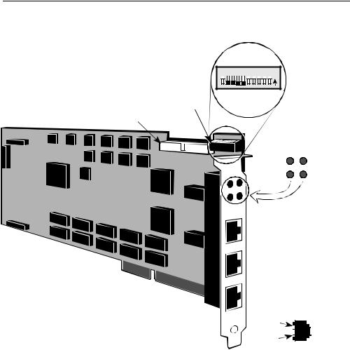
E1 Dual Port Digital PBX Interface Card
Introduction |
The E1 dual port digital PBX interface card supports digital voice communications, |
|
providing integrated network access (see Figure 1-12). The E1 interface card is |
|
installed primarily in Europe and South America. A 2-megabyte E1 card is required |
|
for passing data traffic and voice traffic. |
Description |
|
Each E1 dual port digital PBX interface card uses an Industry Standard Architecture |
|
|
(ISA) bus interface and a Multi-Vendor Integration Protocol (MVIP) bus interface. |
|
The MVIP bus interface provides a multiplexed digital access within the PathBuilder |
|
S24x, 26x, and 27x switch chassis. |
|
The E1 dual port digital PBX interface card has two E1 ports (CAS signaling only), |
|
handles E1 lines with or without CRC4, and supports 120Ω and 75Ω (with the |
|
addition of an optional cable). The interface type is 8-pin modular. |
Function |
|
E1 dual port digital PBX interface cards provide the digital interfaces for |
|
|
connections to a PBX. The dual port digital PBX interface cards bring PCM voice |
|
and channel signaling into the node. The PCM voice data and voice signaling is |
|
routed to a DSPM/SM card over the MVIP bus for compression and transmission to |
|
the motherboard. |
Slot Restriction |
|
The E1 dual port digital PBX interface card can only occupy slot 8 in the PathBuilder |
|
|
S24x, 26x, and 27x switch chassis. |
1-20 |
About the PathBuilder S24x, 26x, and 27x switch |
Hardware Components
E1 Dual Port Digital Figure 1-12 shows an example of the E1 dual port digital PBX interface card.
PBX Interface Card Illustration
109 8 7 6 5 4 3 2 1 N 


 O
O
SW1 DIP Switch Bank
MVIP Bus Interface Connector
Port 49 |
Port 50 |
Alarm LED |
Alarm LED |
Run LED |
SysFail LED |
|
|
Port 49 Interface |
|||
|
|
Port 50 Interface |
|||
|
ISA Bus Interface |
Serial Diagnostic Port |
|||
|
|
||||
|
|
Pin 6 |
|
|
|
|
|
|
|
|
|
|
Figure 1-12. E1 Digital PBX Interface Card |
Pin 1 |
|
|
|
|
|
|
|
||
|
|
|
|
|
|
DIP Switch |
|
|
|
|
|
The E1 dual port digital PBX interface card contains a single DIP switch bank (SW1) |
|||||
Location |
used to assign the card’s I/O base address. |
|
|
|
|
DIP Switch |
|
|
|
|
|
Set the switches as shown in Figure 1-12. |
|
|
|
|
|
Settings |
|
|
|
|
|
About the PathBuilder S24x, 26x, and 27x switch |
1-21 |

Hardware Components
Required cables The following cables, including two pigtail cables, ship with the E1 dual port digital PBX interface card and are required to cable the E1 card to the DSPM/SM cards in the PathBuilder S24x, 26x, and 27x switch node.
|
|
Cable Description |
|
Function |
|
|
|
|
|
|
|
|
|
One 4-position 40-pin |
Connects up to three DSPM/SM cards to |
||
|
|
MVIP ribbon cable |
interconnect digital voice traffic between individual |
||
|
|
|
|
cards in the same PathBuilder S24x, 26x, and 27x |
|
|
|
|
|
switch node. |
|
|
|
|
|
|
|
|
|
One 8-position, 40-pin |
Connects four or more DSPM/SM cards to |
||
|
|
MVIP ribbon cable |
interconnect digital voice traffic between individual |
||
|
|
|
|
cards in the same PathBuilder S24x, 26x, and 27x |
|
|
|
|
|
switch node. |
|
|
|
|
|
|
|
|
|
Two 8-pin modular to DB15 |
For 120Ω connection. |
||
|
|
cables |
|
|
|
|
|
|
|
|
|
|
|
Two 8-pin modular to BNC |
For 75Ω connection. |
||
|
|
cables |
|
|
|
LED Status |
|
|
|
|
|
|
|
|
|
||
The E1 dual port digital PBX interface card contains four LEDs that can be viewed |
|||||
Indicators |
through the rear bracket: |
|
|
||
|
|
|
|
|
|
|
|
LED |
Color |
LED is... |
...Indicating |
|
|
|
|
|
|
|
|
Port 49 |
Yellow |
OFF |
Normal operation |
|
|
|
|
ON |
Carrier failure on Port 49 span |
|
|
|
|
|
|
|
|
Port 50 |
Yellow |
OFF |
Normal operation |
|
|
|
|
ON |
Carrier failure on Port 50 span |
|
|
|
|
|
|
|
|
RUN |
Green |
OFF |
Card failure |
|
|
|
|
ON |
Microprocessor Activity |
|
|
|
|
|
|
|
|
SYSFAIL |
Yellow |
OFF |
Normal operation |
|
|
|
|
ON |
Card failure |
|
|
|
|
|
|
|
|
|
|
|
|
1-22 |
About the PathBuilder S24x, 26x, and 27x switch |
Loading...