


 Loading...
3Com 11a/b/g Wireless Workgroup Bridge User Guide
Model: WL-560 3CRWE675075
http://www.3com.com/
Part No. DUA6750-75AAA01
Published November 2004
Version 1.0.2
3Com Corporation
350 Campus Drive
Marlborough
MA USA 01752-3064
Copyright © 2004, 3Com Corporation. All rights reserved. No part of this documentation may be reproduced in any form or by any means or used to make any derivative work (such as translation, transformation, or adaptation) without written permission from 3Com Corporation.
3Com Corporation reserves the right to revise this documentation and to make changes in content from time to time without obligation on the part of 3Com Corporation to provide notification of such revision or change.
3Com Corporation provides this documentation without warranty, term, or condition of any kind, either implied or expressed, including, but not limited to, the implied warranties, terms or conditions of merchantability, satisfactory quality, and fitness for a particular purpose. 3Com may make improvements or changes in the product(s) and/or the program(s) described in this documentation at any time.
If there is any software on removable media described in this documentation, it is furnished under a license agreement included with the product as a separate document, in the hard copy documentation, or on the removable media in a directory file named LICENSE.TXT or !LICENSE.TXT. If you are unable to locate a copy, please contact 3Com and a copy will be provided to you.
UNITED STATES GOVERNMENT LEGEND
If you are a United States government agency, then this documentation and the software described herein are provided to you subject to the following:
All technical data and computer software are commercial in nature and developed solely at private expense. Software is delivered as “Commercial Computer Software” as defined in DFARS 252.227-7014 (June 1995) or as a “commercial item” as defined in FAR 2.101(a) and as such is provided with only such rights as are provided in 3Com’s standard commercial license for the Software. Technical data is provided with limited rights only as provided in DFAR 252.227-7015 (Nov 1995) or FAR 52.227-14 (June 1987), whichever is applicable. You agree not to remove or deface any portion of any legend provided on any licensed program or documentation contained in, or delivered to you in conjunction with, this User Guide.
Unless otherwise indicated, 3Com registered trademarks are registered in the United States and may or may not be registered in other countries.
3Com and the 3Com logo are registered trademarks of 3Com Corporation.
Intel and Pentium are registered trademarks of Intel Corporation. Microsoft, MS-DOS, Windows, and Windows NT are registered trademarks of Microsoft Corporation. Novell and NetWare are registered trademarks of Novell, Inc. UNIX is a registered trademark in the United States and other countries, licensed exclusively through X/Open Company, Ltd.
IEEE and 802 are registered trademarks of the Institute of Electrical and Electronics Engineers, Inc.
All other company and product names may be trademarks of the respective companies with which they are associated.
ENVIRONMENTAL STATEMENT
It is the policy of 3Com Corporation to be environmentally-friendly in all operations. To uphold our policy, we are committed to:
Establishing environmental performance standards that comply with national legislation and regulations.
Conserving energy, materials and natural resources in all operations.
Reducing the waste generated by all operations. Ensuring that all waste conforms to recognized environmental standards. Maximizing the recyclable and reusable content of all products.
Ensuring that all products can be recycled, reused and disposed of safely.
Ensuring that all products are labelled according to recognized environmental standards.
Improving our environmental record on a continual basis.
End of Life Statement
3Com processes allow for the recovery, reclamation and safe disposal of all end-of-life electronic components.
Regulated Materials Statement
3Com products do not contain any hazardous or ozone-depleting material.
Environmental Statement about the Documentation
The documentation for this product is printed on paper that comes from sustainable, managed forests; it is fully biodegradable and recyclable, and is completely chlorine-free. The varnish is environmentally-friendly, and the inks are vegetable-based with a low heavy-metal content.

CONTENTS
ABOUT THIS GUIDE
|
Conventions |
2 |
|
|
|
|
|
Related Documentation |
2 |
|
|
|
|
|
Accessing Online Documentation |
3 |
|
|||
|
Product Registration and Support |
4 |
|
|||
|
|
|
|
|
|
|
1 INTRODUCTION |
|
|
|
|
||
|
Product Features 5 |
|
|
|
|
|
|
Security |
5 |
|
|
|
|
|
Wireless Network Standards |
6 |
|
|||
|
Network Configuration and Planning |
7 |
||||
|
Example Configurations |
8 |
|
|
|
|
|
|
|
|
|
||
2 INSTALLING THE BRIDGE |
|
|
|
|||
|
Unpacking the Bridge |
9 |
|
|
|
|
|
Observing Safety Precautions |
10 |
|
|||
|
Deciding Where to Place the Bridge 11 |
|||||
|
Wall-Mounting the Bridge |
11 |
|
|||
|
Installing the Locking Bar |
12 |
|
|||
|
Placing the Bridge on a Flat Surface |
13 |
||||
|
Connecting the Bridge |
14 |
|
|
|
|
|
Connecting to a Serial Device |
14 |
|
|||
|
Connecting to an Ethernet Device |
15 |
||||
|
About the Client List |
15 |
|
|
|
|
|
Connecting to a Hub |
15 |
|
|
|
|
|
Connecting to a Network Printer |
16 |
||||
|
Connecting to a Computer |
|
16 |
|
||
|
Checking the LED Indicators |
17 |
|
|||
|
Attaching An External Antenna |
|
18 |
|
||
|
Determining if you Need to Configure the Bridge 18 |
|||||
|
Using the 3Com Installation CD |
21 |
|
|||

3 CONFIGURING THE BRIDGE
|
Using Secure Web Server Connection 23 |
|
|
||||||
|
Using the 3Com Wireless Infrastructure Device Manager |
24 |
|||||||
|
Using the Configuration Management System |
27 |
|
||||||
|
Clearing and Applying System Configuration Settings |
28 |
|||||||
|
Changing System Properties |
29 |
|
|
|
||||
|
Setting IP Network Properties |
30 |
|
|
|
||||
|
Setting Wireless Network Properties |
31 |
|
|
|||||
|
Manually Select Radio Channels |
33 |
|
|
|
||||
|
Setting Up an Ad-Hoc Network |
34 |
|
|
|
||||
|
Changing Wireless Security Settings |
35 |
|
|
|||||
|
Changing RADIUS Settings |
37 |
|
|
|
||||
|
Changing SNMP Settings |
38 |
|
|
|
|
|||
|
Using the Access Control List |
39 |
|
|
|
||||
|
Serial Port |
40 |
|
|
|
|
|
|
|
|
Resetting the Bridge |
42 |
|
|
|
|
|
||
|
Restoring the Bridge to Factory Defaults |
43 |
|
||||||
|
Upgrading the System |
44 |
|
|
|
|
|
||
|
Changing the Administration Login Name and Password 45 |
||||||||
|
Backing up a Configuration |
45 |
|
|
|
||||
|
Restoring a Configuration |
46 |
|
|
|
|
|||
|
Logging Out |
46 |
|
|
|
|
|
|
|
|
Clearing the Ethernet Client List |
46 |
|
|
|
||||
|
Viewing Connection Status |
47 |
|
|
|
||||
|
Viewing System Summary |
47 |
|
|
|
|
|||
|
|
|
|
|
|
|
|
|
|
4 TROUBLESHOOTING |
|
|
|
|
|
|
|
||
|
Diagnosing Problems |
49 |
|
|
|
|
|
|
|
|
Disconnecting the Bridge |
51 |
|
|
|
|
|
||
|
Uninstalling Software and Documentation |
51 |
|
||||||
|
Upgrading Bridge Firmware |
52 |
|
|
|
|
|||

A OBTAINING SUPPORT FOR YOUR 3COM PRODUCT
Register Your Product to Gain Service Benefits 53 Solve Problems Online 53
Purchase Extended Warranty and Professional Services 54 Access Software Downloads 54
Contact Us 54
Telephone Technical Support and Repair 55
END USER LICENSE AGREEMENT
REGULATORY INFORMATION

ABOUT THIS GUIDE
This guide provides all the information you need to install and use the 3Com 11a/b/g Wireless Workgroup Bridge in its default state.
The guide is intended for use by IT managers and experienced network installation and administration professionals who have a basic knowledge of current networking concepts.
If the information in the release notes that are shipped with your product differ from the information in this guide, follow the instructions in the release notes.
Most user guides and release notes are available in Adobe Acrobat Reader Portable Document Format (PDF) or HTML on the 3Com World Wide Web site:
http://www.3com.com/
2 ABOUT THIS GUIDE
Conventions |
Table 1 and Table 2 list conventions that are used throughout this guide. |
||
|
Table 1 |
Notice Icons |
|
|
|
|
|
|
Icon |
Notice Type |
Description |
|
|
|
|
|
|
Information note |
Information that describes important features or |
|
|
|
instructions. |
|
|
Caution |
Information that alerts you to potential loss of data or |
|
|
|
potential damage to an application, system, or device. |
|
|
Warning |
Information that alerts you to potential personal |
|
|
|
injury. |
|
|
|
|
Table 2 Text Conventions
Convention |
Description |
Screen displays |
This typeface represents information as it appears on the |
|
screen. |
Syntax |
The word “syntax” means that you must evaluate the syntax |
|
provided and then supply the appropriate values for the |
|
placeholders that appear in angle brackets. Example: |
|
To change your password, use the following syntax: |
|
system password <password> |
|
In this example, you must supply a password for <password>. |
|
|
The words “enter” |
When you see the word “enter” in this guide, you must type |
and “type” |
something, and then press Return or Enter. Do not press |
|
Return or Enter when an instruction simply says “type.” |
|
|
Keyboard key names |
If you must press two or more keys simultaneously, the key |
|
names are linked with a plus sign (+). Example: |
|
Press Ctrl+Alt+Del |
|
|
Words in italics |
Italics are used to: |
|
■ Emphasize a point. |
|
■ Denote a new term at the place where it is defined in the |
|
text. |
|
■ Identify menu names, menu commands, and software |
|
button names. Examples: |
|
From the Help menu, select Contents. |
|
Click OK. |
|
|
Related |
In addition to this guide, each Bridge documentation set includes the |
Documentation |
following: |

Accessing Online Documentation |
3 |
■Quick Start Guide—printed guide that describes basic installation.
■Online Help—product help systems that describe how to use the Configuration Management System and 3Com Wireless Infrastructure Device Manager.
■Release Note—printed note that describes important product information.
■README.TXT file—text file located on the 3Com Installation CD that describes last-minute product information.
Accessing Online The CD supplied with your Bridge contains the following online Documentation documentation:
■3Com 11a/b/g Wireless Workgroup Bridge User Guide
■3Com Wireless Infrastructure Device Manager Online Help
■3Com 11a/b/g Wireless Workgroup Bridge Configuration Management System Online Help
To access the online documentation from the CD:
1Insert the 3Com Installation CD supplied with your Bridge in the CD-ROM drive.
The setup menu appears. If it does not appear, you can start the setup menu from the Windows Start menu. For example: Start > Run > d:setup.exe.
2In the menu, click View the Documentation to view the Bridge User Guide.
To view the online help, install and launch the Wireless Infrastructure Device Manager or Configuration Management System. See Chapter 3 for instructions.

4 ABOUT THIS GUIDE
Product
Registration and
Support
To register your product with 3Com, go to the following Web page:
http://esupport.3com.com
For support information, see “Obtaining Support for your 3Com Product” on page 53 or log on to the 3Com Web site at http://www.3com.com and navigate to the product support page.
1 INTRODUCTION
3Com wireless technology has all of the benefits of a local area network (LAN) without the constraints and expense of network wiring.
3Com 11a/b/g Wireless LAN products provide easy, affordable, flexible ways to extend wireless networks to more users. This guide shows how you can use the 3Com 11a/b/g Wireless Workgroup Bridge in your office or classroom to connect groups of wired Ethernet client devices to your wireless LAN.
Product Features The 3Com 11a/b/g Wireless Workgroup Bridge includes a robust suite of standards-based security features, and supports wireless network standards including 802.11a and 802.11g.
Security To protect sensitive data broadcast over the radio, 3Com supports Wireless Equivalent Privacy (WEP) RC4 64-bit, 128-bit and 152-bit shared-key encryption. 3Com strengthens this basic security mechanism with additional security features, including:
■MAC address access control lists
■IEEE 802.1x per-port user authentication with RADIUS server authentication support
■Temporal Key Integrity Protocol (TKIP)
■Advanced Encryption Standard (AES)
■WiFi Protected Access (WPA)
■Extensible Authentication Protocol (EAP) support: EAP-TTLS and PEAP
6 CHAPTER 1: INTRODUCTION
Wireless Network Understanding the characteristics of the 802.11a and 802.11g standards
Standards can help you make the best choice for your wireless implementation plans.
802.11a
Ratified in 2002, 802.11a is IEEE’s more recent wireless standard. It operates at the 5 GHz band and supports data rates at up to 54 Mbps. Because there are fewer devices in the 5 GHz band, there’s less potential for RF interference. However, because it is at an entirely different radio spectrum, it is not compatible with 802.11g.
The higher spectrum provides about 50 m (164 ft) of coverage—about half what 802.11g offers.
Consider 802.11a when you need high throughput in a confined space and you are:
■Running high-bandwidth applications like voice, video, or multimedia over a wireless network that can benefit from a five-fold increase in data throughput.
■Transferring large files like computer-aided design files, preprint publishing documents or graphics files, such as MRI scans for medical applications, that demand additional bandwidth.
■Supporting a dense user base confined to a small coverage area. Because 802.11a has a greater number of non-overlapping channels, you can pack more wireless devices in a tighter space.
802.11g
802.11g operates in the 2.4 GHz band at up to 54 Mbps. Ratified in 2003, it supports the widest coverage—up to 100 m (328 ft). However, is subject to a greater risk of radio interference because it operates in the more popular 2.4 GHz band.
802.11b operates at up to 11 Mbps and supports coverage up to 100 m (328 ft).

Network Configuration and Planning |
7 |
Consider 802.11g when you need wider coverage and vendor compatibility and you are:
■ Maintaining support for existing 802.11b users and the existing wireless investment while providing for expansion into 802.11g.
|
■ Implementing a complete wireless LAN solution, including bridges, |
|
gateways, access points and clients; Wi-Fi certification guarantees |
|
compatibility among vendors. |
|
■ Providing access to hot spots in public spaces such as coffee shops or |
|
university cafeterias. |
|
|
Network |
The Bridge can operate in either infrastructure or ad-hoc mode, and can |
Configuration and |
support a stand-alone wireless network configuration or an integrated |
Planning |
configuration with 10/100 Mbps Ethernet LANs. |
|
Operating in infrastructure mode and connected to an Ethernet hub, a |
|
single Bridge can combine up to 16 client devices—such as computers |
|
with network adapters and printers—into a multiclient workgroup. The |
|
workgroup associates with the wired network through a wireless LAN |
|
access point such as the 3Com 11a/b/g Wireless LAN Access Point. |
|
Infrastructure configurations extend your wireless LAN to devices that |
|
would otherwise have to be connected to the wired network. |
|
Operating in ad-hoc mode, two or more Bridges can associate among |
|
themselves and communicate with one another at close range without an |
|
access point. You may wish to set up an ad-hoc network, for example, if |
|
a group is working away from the office, or if a group in the office needs |
|
to share files apart from the wired LAN. |
8 CHAPTER 1: INTRODUCTION
Example |
The following examples illustrate ways you can use the Bridge to |
Configurations |
configure Ethernet client devices into workgroups. (Details for setting up |
|
specific configurations are in “Installing the Bridge” on page 9.) |
Wireless Infrastructure Network
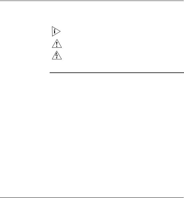
You can connect several computers, including those with non-Windows operating systems, and network printers, as shown in Figure 1.
Figure 1 Wireless Infrastructure Network
Access |
Hub |
|
|
Point |
|
11a/b/g W ireless Workgroup Br idge
Workgroup Ad-Hoc Network
You can provide flexible wireless network association for small groups in areas that cannot be wired, as shown in Figure 2.
Figure 2 Workgroup Ad-Hoc Network
Hub
11a/b/ g Wireless Workgroup Brid ge
Hub
11a/b/ g Wireless Workgroup Brid ge

2 |
INSTALLING THE BRIDGE |
|
This chapter contains the information you need to install and set up the
Bridge. It covers the following topics:
|
■ |
Unpacking the Bridge |
|
■ |
Observing Safety Precautions |
|
■ Deciding Where to Place the Bridge |
|
|
■ |
Connecting the Bridge |
|
■ Checking the LED Indicators |
|
|
■ Attaching An External Antenna |
|
|
■ Determining if you Need to Configure the Bridge |
|
|
■ Using the 3Com Installation CD |
|
|
|
|
Unpacking the |
Make sure that you have the following items, which are included with the |
|
Bridge |
Bridge: |
|
|
■ Power adapter and power cord. |
|
|
■ Standard Category 5 unshielded twisted pair (UTP) Ethernet cable. |
|
|
■ Locking bar (used for securing a wall-mounted installation). |
|
|
■ Rubber feet (four; used for a flat-surface installation). |
|
|
■ |
3Com Installation CD. |
|
For wall-mounting installations, you need the following items, which |
|
|
are not included with the Bridge: |
|
|
■ |
Mounting screws. |
■ Plastic anchors (for drywall mounting).
To secure the Bridge using the locking bar, you need a lock (not supplied).
10 CHAPTER 2: INSTALLING THE BRIDGE
Figure 3 shows the front view of the Bridge, including the LEDs and connecting ports. It also shows the cradle, which is used to mount the Bridge to a wall or to install the Bridge on a flat surface.
Figure 3 Bridge
11a/b/g Wireless
Workgroup Bridge
Power Port
Serial Port
Ethernet Port
Cradle
Observing Safety This equipment must be installed in compliance with local and national
Precautions building codes, regulatory restrictions, and FCC rules. For the safety of people and equipment, only professional network personnel should install the Bridge.
WARNING: To comply with FCC radio frequency (RF) exposure limits, a minimum body-to-antenna distance of 20 cm (8 in.) must be maintained when the Bridge is operational.
WARNING: To avoid possible injury or damage to equipment, you must use either the provided power supply or power supply equipment that is safety certified according to UL, CSA, IEC, or other applicable national or international safety requirements for the country of use. All references to power supply in this document refer to equipment meeting these requirements.
CAUTION: The 3Com power supply (part number 61-0107-000) input relies on a 16A rated building fuse or circuit protector for short circuit protection of the line to neutral conductors.
Deciding Where to Place the Bridge 11
Deciding Where to Place the Bridge in a dry, clean location near the hub, computer, or Place the Bridge printer that will be connected to the Bridge. The location must have a
power source and be within the following distance of a Wi-Fi compliant wireless LAN access point or ad-hoc wireless station:
■For 802.11a compatibility, place the Bridge within 50 m (164 ft) of a Wi-Fi compliant wireless LAN access point.
■For 802.11b/g compatibility, place the Bridge within 100 m (328 ft) of a Wi-Fi compliant wireless LAN access point.
The location should be away from transformers, heavy-duty motors, fluorescent lights, microwave ovens, refrigerators, or other equipment that could cause radio signal interference.
Wall-Mounting the The Bridge comes with a cradle for mounting on a wall. For additional Bridge security, the Bridge also comes with a locking bar, which can be used with a security lock (not provided) to lock the Bridge to the cradle after
the Bridge is mounted to a wall.
To wall-mount the bridge:
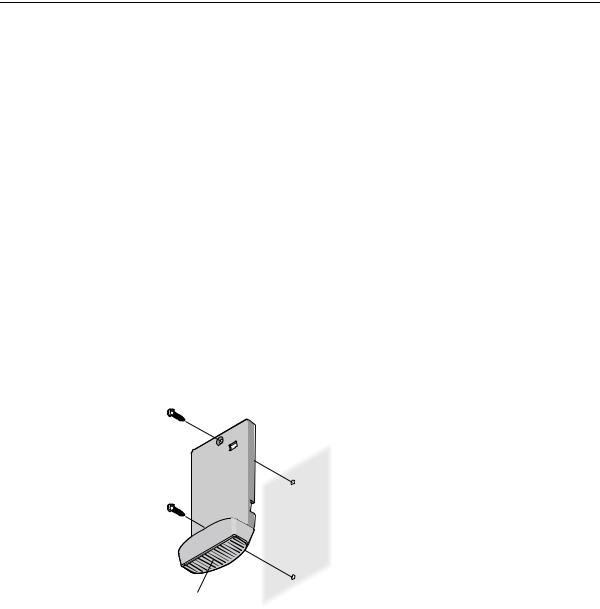
1Screw the cradle to a wall, as shown in Figure 4.
Figure 4 Wall-Mounting the Bridge
Cradle
12 CHAPTER 2: INSTALLING THE BRIDGE
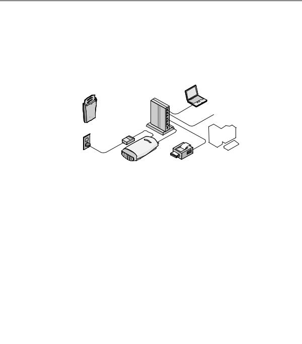
2Route the power and Ethernet cables through the large opening in the cradle. Figure 5 shows a cable being routed under the cradle.
Figure 5 Routing Cable Under the Cradle
3Connect the power and Ethernet cables to the ports on the Bridge.
4Snap the Bridge onto the cradle.
Installing the For additional security, install the locking bar in the cradle after the Bridge Locking Bar is mounted to the wall. Use your own lock to secure it in place.
To install the locking bar:
1Insert the locking bar through the opening in the side of the cradle, as shown in Figure 6.
Figure 6 Inserting the Locking Bar
.11a  .11g
.11g  .100 .10
Deciding Where to Place the Bridge 13
2Push the locking bar through the opening until the hole on the locking bar is exposed.
3Insert a lock through the hole on the locking bar, and then close the lock to secure it in place, as shown in Figure 7.
Figure 7 Securing the Locking Bar
|
|
100 |
10 |
|
11g |
|
. |
11a |
. |
|
|
. |
|
|
|
|
|
|
|
. |
|
|
|
Placing the Bridge on The Bridge comes with four rubber feet that can be used to install the a Flat Surface Bridge on a flat surface such as a table or desktop.
CAUTION: Do not place the Bridge on any type of metal surface. Select a location that is clear of obstructions and provides good reception.
Remove the backing from the rubber feet and attach them to the bottom of the cradle. After the rubber feet are installed, place the Bridge on a flat surface.

14 CHAPTER 2: INSTALLING THE BRIDGE
Connecting the |
The Bridge has power, Ethernet, and serial ports, as shown in Figure 8. |
Bridge |
Before connecting the Bridge to an Ethernet device, connect the power. |
|
Figure 8 Connecting the Power |
|
Power |
|
Cable |
Ethernet
Cable
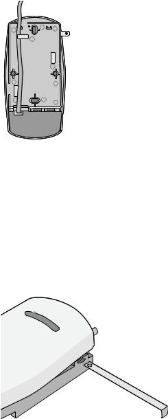
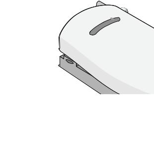
Connecting to a The Bridge can also be connected to a serial device, as shown in Figure 9. Serial Device Serial cables come with a variety of connector sizes. If your connector is large and prevents the cradle from being attached to the Bridge, remove
the end cap on the cradle. This allows the connector to extend through the cradle.
Figure 9 Connecting a Serial Cable
Serial Cable
Connecting the Bridge |
15 |
Connecting to an The Bridge is designed to be connected to an Ethernet client device such Ethernet Device as a hub, computer, or printer.
CAUTION: To avoid the possibility of a transmission loop situation between the Bridge and an access point, which could disrupt network operation, do not connect a Bridge that is set in Wireless Client (Infrastructure) mode directly to the LAN (for example, through a wall port or through a hub that is connected directly to the LAN).
About the Client List
Connecting to a Hub
The Bridge supports up to 16 specific Ethernet client devices. It uses a client list of MAC addresses to keep track of specific devices that have been connected.
After 16 different devices have been connected, the client list is full, and you must clear it before the next new device can associate with the network through the Bridge.
To clear the list, you must access the Bridge’s Configuration Management System. Details are in “Clearing the Ethernet Client List” on page 46.
You can supply network connections for up to 16 devices, such as computers and network printers, by connecting the Bridge to an Ethernet hub, as shown in Figure 10.
Figure 10 Connecting to a Hub
Access |
Hub |
|
|
Uplink |
Port |
||
Point |
|||
|
|
11a/b/g Wireless Workgroup Brid ge
You can directly connect the Bridge to a hub that does not have an uplink (MDIX) port, without the need of an Ethernet crossover cable.
Loading...